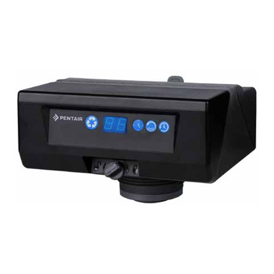
Summary of Contents for Pentair AUTOTROL 363
- Page 1 AUTOTROL 363 DEMAND AUTOMATIC FILTER VALVE ® Service Manual ©2014 Pentair Residential Filtration, LLC www.pentairaqua.com/pro...
-
Page 2: Table Of Contents
TABLE OF CONTENTS Mechanical MANUAL OVERVIEW ..............2 • Do not use petroleum-based lubricants such as SAFETY INFORMATION ............2 petroleum jelly, oils, or hydrocarbon-based lubricants. TYPICAL TOOLS AND FITTINGS REQUIRED ......3 Use only 100% silicone lubricants. VALVE DIMENSIONS ..............3 • All plastic connections should be hand tightened. -
Page 3: Typical Tools And Fittings Required
SAFETY INFORMATION continued VALVE DIMENSIONS Outdoor Locations It is recommended that the equipment be installed indoors. When the water conditioning system must be installed outdoors, several items must be considered. • Moisture — The valve and controller are rated for NEMA 3 locations. -
Page 4: Valve Layout
VALVE LAYOUT EQUIPMENT INSTALLATION If you are also installing a water softener, the softener should Inlet be installed downstream of this system. Outlet Grounding the Plumbing It is important that the plumbing system be electrically grounded. When a water treatment system is installed a nonmetallic bypass valve may interrupt the grounding. - Page 5 EQUIPMENT INSTALLATION continued Drain Line Connection Firmly insert connector into the valve body. Press locking clip into position. Make certain the clip is fully engaged. NOTE: Standard commercial practices are expressed here. Local codes may require changes to the following To remove a clip: suggestions.
-
Page 6: System Startup
SYSTEM STARTUP CONTROL OPERATION AND LAYOUT The system will now need to be placed into operation. Please Large LED Display review MANUALLY INITIATING A CLEANING CYCLE on page A large two digit LED readout is highly visible in most 7 before attempting startup. installation settings. -
Page 7: Programming The 606F Demand Control
PROGRAMMING THE 606F DEMAND CONTROL Accessing History Values Time of Day: Press to display the current time value in The control features a review level that displays the operation hours. The time value is displayed as a number from 0 to 23, history of the system. -
Page 8: Remote Regeneration
PROGRAMMING THE 606F DEMAND CONTROL continued Quick Cycling The Control Quick Cycling Press and hold for three seconds to initiate an immediate cleaning cycle. The control will cycle to the backwash cycle step. 1. Press and release to display "C1" (backwash). 2. -
Page 9: Valve Assembly
VALVE ASSEMBLY 4002436 Rev A Item No. Part No. Description Item No. Part No. Description 1 ....1 ..4002555 ....Kit, Valve Discs, 360 Series Filter ..4002469 .....Kit, DLFC, 20GPM, NPT, 360, Fltr 2 ....1 ..4002211 ....Top Plate, 360 Series Filter .. -
Page 10: Troubleshooting
TROUBLESHOOTING Control Error Codes Problem Possible Cause Solution E1 is displayed. Program settings have been corrupted. Press any key. Reprogram control. If E1 does not clear, replace control. E3 is displayed. Control does not detect the camshaft position and is Wait until the control returns to the service position. -
Page 11: Flow Diagrams
FLOW DIAGRAMS SERVICE BACKWASH Untreated Water Untreated Water Backwash Treated Water Inlet Inlet Outlet Outlet Drain Control Drain Drain Drain Control Valve No. Valve No. 1. Closed 1. Open 2. Open 2. Closed 3. Closed 3. Open 4. Closed 4. Closed Media Tank Media Tank FAST RINSE... -
Page 12: Flow Performance Data Charts
FLOW PERFORMANCE DATA CHARTS Service Cv = 5.43 FLOW IN GPM Cv = 3.74 FLOW IN GPM 12 • Autotrol 363 Demand Automatic Filter Valve ®... - Page 13 P: 262.238.4400 | www.pentairaqua.com | 800.279.9404 | F: 262.518.4404 | tech-support@pentair.com All Pentair trademarks and logos are owned by Pentair, Inc. All other brand or product names are trademarks or registered marks of their respective owners. Because we are continuously improving our products and services, Pentair reserves the right to change specifications without prior notice.


Need help?
Do you have a question about the AUTOTROL 363 and is the answer not in the manual?
Questions and answers