Advertisement
Table of Contents
Advertisement
Table of Contents

Related Manuals for Pentair Autotrol Performa 400 Series


Summary of Contents for Pentair Autotrol Performa 400 Series
- Page 1 Autotrol Performa™ ValVe with 400 SerieS Control ® water Conditioning Control SyStem Service Manual 460TC 460TC BRINE/ SLOW RINSE DAYS CLOCK BACKWASH FAST RINSE/ CONDITIONED WATER REFILL PRESS MANUAL REGENERATION: TO SET TIME PRESS BUTTON & RELEASE www.pentairaqua.com...
-
Page 2: Table Of Contents
tABlE oF CoNtENtS INStAllAtIoN INSTALLATION ..............2 All plumbing and electrical connections must conform to local codes. PLACING CONDITIONER INTO OPERATION ......4 Inspect unit carefully for carrier shortage or shipping damage. 400 SERIES CONTROL SETTINGS ........5 The 268 water conditioner’s control valve REMOVING THE VALVE ASSEMBLY FOR SERVICE ....8 conforms to NSF/ANSI 44 and 61 for materials PREVENTIVE MAINTENANCE ..........8... - Page 3 INStAllAtIoN continued IMPortANt: Never insert drain line into a drain, sewer line Water line Connection or trap. Always allow an air gap between the drain line and the wastewater to prevent the The installation of a bypass valve system is recommended to possibility of sewage being back-siphoned into provide for occasions when the water conditioner must be the conditioner.
-
Page 4: Placing Conditioner Into Operation
PlACINg CoNDItIoNEr INto oPErAtIoN Electrical Connection After all previous steps have been completed, the unit is ready to be placed into operation. Follow these steps carefully. 100 VAC, 115 VAC, and 230 VAC units: Remove twist tie from 1. Remove control valve cover by first releasing the plastic the power cord and extend cord to its full length. -
Page 5: 400 Series Control Settings
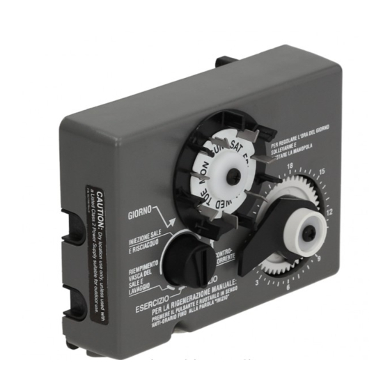
400 SErIES CoNtrol SEttINgS 460i Control 440i Control (obsolete) Water Flow Indicator Raised Tab Hour Time Display PM Indicator Skipper Wheel Skipper Pins Day Arrow Access Door Jumper Spare Time Set Button Indicator Knob Jumper Timer Locking Pin Time Arrow Indicator Knob Transformer Timer Knob... - Page 6 400 SErIES CoNtrol SEttINgS time of Day Setting continued With the jumper on the set of pins next to the word TIME Capacity Setting (Figure 11), set the time of day to the closest hour by pressing the black TIME SET button. PM hours are indicated by a light Move the jumper to the set of pins next to the word CAPACITY next to the letters PM on the display window.
- Page 7 400 SErIES CoNtrol SEttINgS guest Cycle continued When abnormally high water usage exhausts your Common Features water conditioner’s capacity ahead of schedule, an extra When using the Performa valve with the 440i or 460i controls, regeneration can be achieved. Depress the indicator knob on there are several features and procedures that are unique to the 440i (Figure 5) with a wide-blade screwdriver and turn the 400 series controls.
-
Page 8: Removing The Valve Assembly For Service
rEMoVINg tHE VAlVE ASSEMBlY For SErVICE 1. Unplug the power cord. Lever Up 2. Shut off water supply or put bypass valve(s) into bypass position. 3. Remove cover and with screwdriver, relieve tank pressure by pushing open valve No. 7 (rear flapper) on control as shown (Figure 15). - Page 9 PrEVENtIVE MAINtENANCE continued Disinfection of Water Conditioners The materials of construction of the modern water conditioner will not support bacterial growth, nor will these materials Injector Screen contaminate a water supply. However, the normal conditions existing during shipping, storage and installation indicate the advisability of disinfecting a conditioner after installation, before the conditioner is used to treat potable water.
-
Page 10: Specifications
SPECIFICAtIoNS DAYS CLOCK Hydrostatic Test Pressure 300 psi (20.69 bar) Working Pressure 20-125 psi (1.38 - 8.62 bar) Standard Electrical Rating 115V 60 Hz Optional Electrical Rating 115V 50 Hz, 230V 50 Hz, 200V 60Hz, 24V 60 Hz, 24V 50 Hz, 100V 60 Hz, 100V 50 Hz, 12V 50 Hz/ transformer, 12V 60 Hz/transformer Electrical Cord (standard rating) 60-inch (1.5 m) 3-wire with plug... -
Page 11: Pressure Graphs
PrESSurE grAPHS Injector #1031363 Injector #1031364 "A" in a 268 Valve "B" in a 268 Valve 1.00 0.30 0.20 1.25 Total 0.25 Total 0.75 1.00 0.15 0.20 Rinse Rinse 0.75 0.50 0.15 0.10 Brine Draw Brine Draw 0.50 0.10 0.25 0.05 0.25 0.05... -
Page 12: Control Valve
CoNtrol VAlVE Identification of Control Valving 7 Backwash 3 Inlet Drain Valve 5 Refill Valve Valve 1 Brine Valve 6 Rinse Drain Valve 4 Outlet Valve 2 Bypass Valve Valve Disc Principle of operation 12 • Autotrol Performa Valve with 400 Series Control water Conditioning Control System ®... -
Page 13: Flow Diagrams
FloW DIAgrAMS 3 Brining/Slow rinse Position 1 Service Position Hard Water Soft Water Hard Water Soft Water Brine Adjustment Brine Inlet Adjustment Inlet Outlet Outlet Valve No. 1 - Open Valve No. Drain 2 - Open 1 - Closed Drain 3 - Closed 2 - Closed 4 - Closed... -
Page 14: Replacement Parts
rEPlACEMENt PArtS Item No. Part No. Description Item No. Part No. Description 1 ....1 ..1035606 ....Valve Assembly, w/o Flow Controls 11 ....1 ..1010429 ....O-Ring (460i, 460TC) 12 ....1 ..1035622 ....Tank Ring 2 ....1 ........Camshaft: 13 ....1 ........Plumbing Adapter Kits: ..1035625 ....440i, 460i Standard ..1001606 ....3/4-inch Copper Tube Adapter Kit ..1035627 ....440i, 460i Extra Salt **... - Page 15 rEPlACEMENt PArtS continued 460tC Control (3) 440i Control (obsolete)(1) 460TC DAYS CLOCK 1265 Bypass (4) 460i Control (2) Item No. Part No. Description 1....1 ........440i Control (6 day or 7 day) 2....1 ........460i Control 3....1 ..4001086 .....460TC Control 4....1 ..1040930 .....1265 Bypass Not Shown: 1 ..
-
Page 16: Troubleshooting
trouBlESHootINg The technology upon which the Autotrol Performa control valve is based is well established and proven in service over many years. However, should a problem or question arise regarding the operation of the system, the control can very easily be serviced. - Page 17 trouBlESHootINg continued 440i Control troubleshooting Problem Cause Correction Transformer or motor not connected. Connect power. Defective timer motor. Replace motor. Control will not regenerate automatically. Skipper pins not down on timer skipper wheel. Depress pins for days regeneration required. Binding in gear train of timer. Replace timer.
- Page 18 trouBlESHootINg continued Problem Cause Correction Continuous regeneration. Broken switch activator on gear. Replace timer. Camshaft does not stop at the end Defective switch. Replace timer. of regeneration. Electric cord unplugged. Connect power. No electric power at outlet. Repair outlet or use working outlet. Control will not regenerate Defective motor.
- Page 19 Autotrol • 19 Performa Valve with 400 Series Control water Conditioning Control System ®...
- Page 20 All Pentair trademarks and logos are owned by Pentair, Inc. or its affiliates. All other registered and unregistered trademarks and logos are the property of their respective owners. Because we are continuously improving our products and services. Pentair reserves the right to change specifications without prior notice.
Need help?
Do you have a question about the Autotrol Performa 400 Series and is the answer not in the manual?
Questions and answers