
Related Manuals for Pentair AUTOTROL 740


Summary of Contents for Pentair AUTOTROL 740
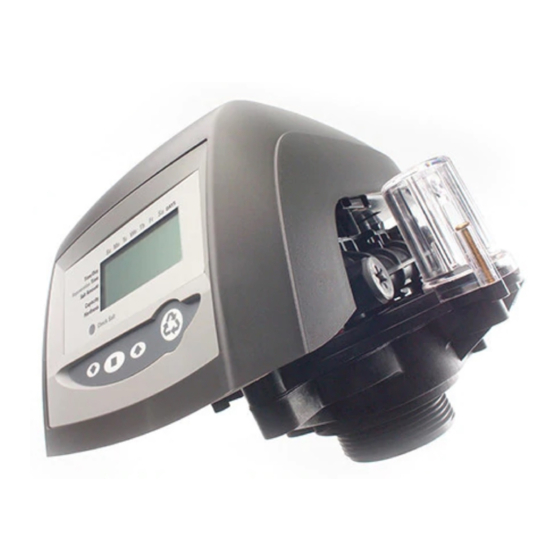
- Page 1 AUTOTROL 740/760 CONTROL 255 & PERFORMA SERIES VALVES ® (268, 268 FA) SERVICE MANUAL www.pentairaqua.com...
- Page 2 TABLE OF CONTENTS • Do not use lead-based solder for sweat solder MANUAL OVERVIEW ............2 connections. SAFETY INFORMATION ............2 • The drain line must be a minimum of 1/2" diameter. Use LOGIX™ SERIES INSTALLER QUICK-START SHEET ....3 3/4" pipe if the backwash flow rate is greater than 5 GPM (18.9 Lpm) or the pipe length is greater than 20 feet (6 SYSTEM SPECIFICATIONS ...........6 EQUIPMENT INSTALLATION ..........
- Page 3 LOGIX™ SERIES INSTALLER QUICK-START SHEET Initial Start-up Step-by-step Instructions Logix Series Controllers Step 1: Program System Size See: Determining If You Have a 740 or 760 Control on page SU MO TU WE TH FR SA DAYS SU MO TU WE TH FR SA DAYS 19 to identify your controller.
- Page 4 LOGIX™ SERIES INSTALLER QUICK-START SHEET CONTINUED Step 6: Amount of Regenerant used per Regeneration Step 4: Set Regen Time SU MO TU WE TH FR SA DAYS SU MO TU WE TH FR SA DAYS Time & Day Time & Day SU MO TU WE TH FR SA DAYS Regen Time &...
- Page 5 LOGIX™ SERIES INSTALLER QUICK-START SHEET CONTINUED Resetting The Control For system start-up procedure, including: purging the mineral SU MO TU WE TH FR SA DAYS SU MO TU WE TH FR SA DAYS tank, refilling the regenerant tank, and drawing regenerant, Time &...
- Page 6 SYSTEM SPECIFICATIONS The systems below have been Tested and Certified by WQA to NSF/ANSI Std. 44 and NSF/ANSI 372 for “Lead Free” compliance. The 255 valve and 268 valve have been Tested and Certified by WQA to NSF/ANSI Std 61 Section 8 Mechanical Devices. WQA Certified 255 Valve WQA Certified 268 Valve Systems...
- Page 7 SYSTEM SPECIFICATIONS CONTINUED AUTOTROL • 7 740/760 Control 255 & Performa Series Valves (268, 268FA) Service Manual ®...
- Page 8 SYSTEM SPECIFICATIONS CONTINUED 8 • AUTOTROL 740/760 Control 255 & Performa Series Valves (268, 268FA) Service Manual ®...
- Page 9 SYSTEM SPECIFICATIONS CONTINUED AUTOTROL • 9 740/760 Control 255 & Performa Series Valves (268, 268FA) Service Manual ®...
- Page 10 SYSTEM SPECIFICATIONS CONTINUED 10 • AUTOTROL 740/760 Control 255 & Performa Series Valves (268, 268FA) Service Manual ®...
- Page 11 EQUIPMENT INSTALLATION Valve Features System Regeneration Cycles Right Side 255 Valve One Piece Valve Manifold Disc Spring 1. Service (Downflow) — Cycle C0: Connection Optical Sensor Untreated water is directed down through the resin bed and up Control Refill Controller through the riser tube.
- Page 12 EQUIPMENT INSTALLATION CONTINUED LCD Display One Piece Valve Right Side Performa Valve Disc Spring Optical Sensor SU MO TU WE TH FR SA DAYS Time & Day Control Valve Discs Regen Time & Day Salt Module Mount Front Capacity x100 Hardness Down Manual Regen...
- Page 13 The inlet water must be connected to the inlet down into normal operating limits the display will return Water WARNING: Water port of the valve. When replacing non-Pentair to normal. A protective cover (P/N 1267811) should assist Conditioner Conditioner Water valves, the inlet and outlet may be with high temperature applications.
- Page 14 EQUIPMENT INSTALLATION CONTINUED Waste connections or drain outlet shall be designed NOTE: and constructed to provide for connection to the sanitary waste system through an air-gap of 2 pipe diameters or 1 inch (22 mm) whichever is larger. Regenerant Line Connection Never insert drain line directly into a drain, WARNING: sewer line, or trap (Figure 8).
- Page 15 EQUIPMENT INSTALLATION CONTINUED Electrical Connection Treated Water Indicator (normal operation) This valve and control are for dry location use only CAUTION unless used with a Listed Class 2 power supply suitable for outdoor use. Treated Water Slot All 700 Series controllers operate on 12-volt alternating current power supply.
- Page 16 SYSTEM START UP Step 2: Program Time of Day Initial Power-Up SU MO TU WE TH FR SA DAYS Time & Day Initial Power Up – (Camshaft proceeds to HOME position) SU MO TU WE TH FR SA DAYS Time & Day Capacity Regen Time &...
- Page 17 SYSTEM START UP CONTINUED Step 8: Estimated Capacity Step 5a: Set Calendar Override (760 Demand Control Only) SU MO TU WE TH FR SA DAYS Time & Day SU MO TU WE TH FR SA DAYS Time & Day Regen Time & Day Regen Time &...
- Page 18 SYSTEM START UP CONTINUED D. Do not let the water flow down the line to the tank for 4. Fill the media tank with water. more than one to two minutes, or the tank may overfill. A. While the controller is in cycle C1 (Backwash), open the E.
- Page 19 740, 740C or 760, 760C A variable reserve saves salt and water by only regenerating when absolutely necessary, and ensures enough soft water for ® Pentair Water USA typical high-water usage days. Glendale, WI Operations Each day of regeneration the controller reviews the last...
- Page 20 PROGRAMMING CONTINUED Programming Conventions 11. When "x2" is displayed, a second regeneration has been called for. The 700 Series controller is programmed using the buttons on 12. The recycle sign is displayed (flashing) when a regeneration the keypad. The programming instructions will be described at the next time of regeneration has been called for.
- Page 21 PROGRAMMING CONTINUED Days Between Regeneration Setting (740 FA) To Advance Regeneration Cycles: To set the days between regenerations, consult the media • Press and hold SET - showing current cycle time. manufacturer for the actual capacity of the media. • Simultaneously press SET and UP to advance on cycle. An In general, manganese greensand has a capacity of 10,000 hourglass will display while cam is advancing.
- Page 22 PROGRAMMING CONTINUED Accessing History Values 700 Series Advanced Programming The Logix control features a review level that displays the operation history of the system. This is a great troubleshooting UP arrow tool for the control valve. To access history values, press and hold SET and DOWN for five seconds to view the "H"...
- Page 23 PROGRAMMING CONTINUED 740/760 Professional Programming To enter Level II (Professional Programming) and change a setting: If a button is not pushed for thirty seconds the NOTE: controller returns to normal operation mode. Action Duration Display Pushing the UP and DOWN arrows for 5 seconds returns the controller to normal operation.
- Page 24 SERVICE AND MAINTENANCE To install control module: Cover The cover provides protection for the controller, wiring, and other components. This cover will be removed for most service and maintenance. When installed, the cover provides NEMA 3 water protection. This protects from falling water up to 30 degrees from vertical. Slots for Motor and To remove cover: Wire Clips...
- Page 25 SERVICE AND MAINTENANCE CONTINUED Optical Sensor When looking at the end of the camshaft, numbers are visible in the hollow of the cup. An arrow on the top plate points to the The optical sensor is mounted to the top plate. The camshaft current marking.
- Page 26 5. If installing the motor harness the connector to the optical The front end cam switch is available as a kit from Pentair Water. sensor can be clipped in place. 6. Connect the harness to the back of the controller.
- Page 27 2. Remove cover. Terminal Block (Optional) 3. Remove motor. 4. Remove camshaft. The Pentair Water valve is rated for low WARNING: 5. Place unit in bypass. voltage microswitch components only. Using a high voltage switch may result in damaged 6.
- Page 28 The Pentair Water valve discs are made from a NOTE: A. Drop screw of same size and thread into the hole.
- Page 29 SERVICE AND MAINTENANCE CONTINUED Disinfection Of Water Conditioners The materials of construction of the modern water conditioner will not support bacterial growth, nor will these materials contaminate a water supply. During normal use, a conditioner may become fouled with organic matter, or in some cases with bacteria from the water supply.
- Page 30 ASSEMBLY DIAGRAMS 255 Valve 17B* 18A* Do not use flow control ball with #17B or 18A. WARNING: 30 • AUTOTROL 740/760 Control 255 & Performa Series Valves (268, 268FA) Service Manual ®...
- Page 31 ASSEMBLY DIAGRAMS CONTINUED Item No. Part No. Description Item No. Part No. Description 1 ....1 ..1244650 ..255 Valve Assembly, w/o 15 ....1 .......Injector (High Efficiency) Flow Controls Options 2 ....1 ..1033784 ..255 Tank Adapter New Style ..1035730 ..“E” Injector (HIgh Efficiency) - Yellow (6-inch tank) 3 ....1 ..
- Page 32 ASSEMBLY DIAGRAMS CONTINUED Item No. Part No. Description * ..........Piping Boss Kit (includes hardware): ..3023763 ..3/4-inch NPT, SS 3/8-inch NPT Drain ..3023749 ..1-inch NPT, SS 1/2-inch NPT Drain ..3023761 ..3/4-inch BSPT, SS 3/8-inch BSPT Drain ..3023747 ..1-inch BSPT, SS 1/2-inch BSPT Drain ..
- Page 33 ASSEMBLY DIAGRAMS CONTINUED Performa Valve 10A* Do not use the flow control ball with #6B or 10A. WARNING: AUTOTROL • 33 740/760 Control 255 & Performa Series Valves (268, 268FA) Service Manual ®...
- Page 34 ASSEMBLY DIAGRAMS CONTINUED Item No. Part No. Description Item No. Part No. Description 1 ....1 ..1244651 ..Valve Assembly w/o Flow 9 ....1 .......Injector (High Efficiency) Controls Options: * .....18 ..1234170 ..Screw, Top Plate, 8-18 x ..1035730 ..“E” Injector (HIgh Efficiency) 0.56-inch Self Tap - Yellow (6-inch tank) 2 ....1 ..
- Page 35 ASSEMBLY DIAGRAMS CONTINUED Item No. Part No. Description 16 ....1 .......Plumbing Adapter Kits: ..1001606 ..3/4-inch Copper Tube Adapter Kit ..1001670 ..1-inch Copper Tube Adapter ..1001608 ..22-mm Copper Tube Adapter ..1001613 ..3/4-inch CPVC Tube Adapter ..1001614 ..1-inch CPVC Tube Adapter ..
- Page 36 ASSEMBLY DIAGRAMS CONTINUED SU MO TU WE TH FR SA DAYS Time & Day Regen Time & Day Salt Capacity x100 Hardness Su Mo Tu We Th Fr Sa DAYS Time/Day Regeneration Time/Day Salt Amount Item No. Part No. Description Item No.
- Page 37 TROUBLESHOOTING 700 Series Controller Troubleshooting Problem Cause Correction ERR 1 is displayed Controller power has been connected and the Press the UP arrow and the control should reset. control is not sure of the state of the operation. ERR 2 is displayed Controller power does not match 50 or 60 Hz.
- Page 38 TROUBLESHOOTING CONTINUED System Troubleshooting Problem Cause Correction Brine tank overflow. Uncontrolled brine refill flow rate. Remove brine control to clean ball and seat. Air leak in brine line to air check. Check all connections in brine line for leaks. Refer to instructions.
- Page 39 TROUBLESHOOTING CONTINUED Problem Cause Correction Run out of conditioned water Improper regeneration. Repeat regeneration, making certain that correct between regenerations. regenerant dosage is used. Incorrect regenerant setting. Set P6 to proper level. See salt setting chart. Incorrect hardness or capacity settings. Set to correct values.
- Page 40 FLOW DIAGRAMS Backwash Position 255 Valve Hard Water Service Position Soft Water Air Check Hard Water Soft Water Air Check Inlet Inlet Outlet Outlet Drain Control Drain Drain Control Valve No. Drain 1-Closed Valve No. 2-Closed 1-Closed 3-Open 2-Open 4-Open 3-Open 5-Closed 4-Closed...
- Page 41 FLOW DIAGRAMS CONTINUED Repressurize Position Fast Rinse Position Hard Water Hard Water Soft Water Soft Water Air Check Air Check Inlet Inlet Outlet Outlet Drain Control Drain Control Drain Drain Valve No. Valve No. 1-Closed 1-Closed 2-Closed 2-Open 3-Closed 3-Closed 4-Open 4-Open 5-Closed...
- Page 42 FLOW DIAGRAMS CONTINUED Backwash Position Performa Valve Service Position Hard Water Soft Water Hard Water Soft Water Inlet Inlet Outlet Backwash Flow Outlet Control Drain Valve No. Drain 1-Closed Valve No. 2-Open 1-Closed 3-Closed 2-Closed 4-Open 3-Open 5-Closed 4-Open 6-Closed 5-Closed 7-Open Mineral Tank...
- Page 43 FLOW DIAGRAMS CONTINUED FLOW DATA CHARTS Fast Rinse Position 255 Valve Flow Data Flow Rate (m /hr) Hard Water Soft Water 1.10 1.00 0.90 0.80 Inlet 0.70 0.60 0.50 Outlet 0.40 0.30 0.20 0.10 LWR 5236 BW LWR 4630 SVC 0.00 Drain Valve No.
- Page 44 FLOW DATA CHARTS CONTINUED Injector Performance Graphs Injector “J” (Light Blue) Injector “F” (Peach) For 10-inch Tanks For 7-inch Tanks / hr 0.80 0.18 0.35 0.08 0.16 0.07 0.30 0.14 0.60 0.06 0.25 0.12 0.05 0.20 0.10 0.40 0.04 0.08 0.15 0.03 0.06...
- Page 45 AUTOTROL • 45 740/760 Control 255 & Performa Series Valves (268, 268FA) Service Manual ®...
- Page 46 46 • AUTOTROL 740/760 Control 255 & Performa Series Valves (268, 268FA) Service Manual ®...
- Page 47 AUTOTROL • 47 740/760 Control 255 & Performa Series Valves (268, 268FA) Service Manual ®...
- Page 48 All Pentair trademarks and logos are owned by Pentair, Inc. or its affiliates. All other registered and unregistered trademarks and logos are the property of their respective owners. Because we are continuously improving our products and services. Pentair reserves the right to change specifications without prior notice.
Need help?
Do you have a question about the AUTOTROL 740 and is the answer not in the manual?
Questions and answers
How do I set up the Autotrol 700 series to be a flow through carbon filter
To set up the Pentair Autotrol 700 series part number 740 as a flow-through carbon (FA) filter, follow these steps:
1. Program as normal for FA filter applications – Refer to the section "Programming the 700 for FA Filter Applications".
2. Initial Start-Up Procedure – Follow steps 1–4 of the initial start-up. After steps 1–4, the controller will operate most systems.
3. Step 4 – Set Regeneration Time:
- Default regen time is 2:00 AM.
- Press SET to make the time flash.
- Use UP/DOWN buttons to change the time.
- Press DOWN to proceed to the next step.
Make sure to complete all programming steps specific to FA filter use and confirm settings such as system size, time, day, and salt capacity are configured correctly.
This answer is automatically generated