
Related Manuals for Omron NX1P


Summary of Contents for Omron NX1P
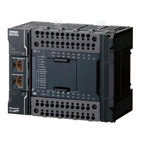
- Page 1 Mac hi ne A utomati on Controll er NX1P Practices Guide for NX1P Programming NX1P2-[][][][] SYSMAC-SE20[][] P122-E1-01...
- Page 2 Trademarks • Sysmac and SYSMAC are trademarks or registered trademarks of OMRON Corporation in Japan and other countries for OMRON factory automation products. • Windows is either a registered trademark or trademark of Microsoft Corporation in the United States and/or other countries.
-
Page 3: Introduction
Introduction Thank you for purchasing an NX-series NX1P2 CPU Unit and the Sysmac Studio. This NX1P Programming Practices Guide for Beginners (hereafter referred to as “this Guide”) describes the differences in programming between the NX1P and traditional controllers and the programming procedures using the Sysmac Studio that are required to use an NX1P2 CPU Unit for the first time. -
Page 4: Terms And Conditions Agreement
Exclusive Warranty mron’s exclusive warranty is that the Products will be free from defects in materials and workmanship for a period of twelve months from the date of sale by Omron (or such other period expressed in writing b y Omron). Omron disclaims all other warranties, express or implied. - Page 5 It may represent the result of Omron’s test conditions, and the user must correlate it to actual application requirements. Actual performance is subject to the Omron’s Warranty and Limitations of Liability.
- Page 6 OMRON will replace defective media without charge. If OMRON is unable to replace defective media or correct the Software, the liability of OMRON and the User’s remedy shall be limited to the refund of the license fee paid to OMRON for the Software.
-
Page 7: Precautions
When building a system, check the specifications for all devices and equipment that will make up the system and make sure that the OMRON products are used well within their rated specifications and performances. Safety measures, such as safety circuits, must be implemented in order to minimize the risks in the event of a malfunction. -
Page 8: Related Manuals
Related Manuals The followings are the manuals related to this manual. Use these manuals for reference. Manual name Cat. No. Model Application Description NX1P2- □□□□ NX-series W578 Learning the basic An introduction to the entire NX1P2 NX1P2 CPU Unit specifications of the system is provided along with the Hardware User's NX1P2 CPU Units,... - Page 9 Manual name Cat. No. Model Application Description NJ/NX-series W508 NX701-□□□□ Learning about the The motion control instructions are Motion Control NJ501-□□□□ specifications of the described. When programming, use this Instructions NJ301-□□□□ motion control manual together with the NJ-series CPU Reference Manual NJ101-□□□□...
-
Page 10: Revision History
Revision History A manual revision code appears as a suffix to the catalog number on the front and back covers of the manual. Cat. No. P122-E1-01 Revision code Revision code Date Revised content September 2017 Original production... -
Page 11: Table Of Contents
Revision History ..................... 10 Programming the NX1P ............14 Overview ......................15 Features of NX1P Programming ..............16 1-2-1 Challenges in Development and Solutions Using the NX1P ..... 16 1-2-2 Easy to Add Programs ............... 17 1-2-3 Easy Motion Programming ..............18 1-2-4 Structured Text Language for Easy Mathematical Processing .. - Page 12 Checking the Operation of the Program (Watch Tab Page) ....60 Example of a Ladder Program Using Date and Time ........62 3-7-1 Programming the NX1P Using Date and Time ........62 3-7-2 Exercise: Continuous Operating Time of Escalator ......62 Fundamentals of Programming to Reduce Development Time .......66...
- Page 13 Structure of ST and Example ............99 6-1-4 Operators ................... 99 NX1P Programming in ST ................100 6-2-1 Writing an ST Program for NX1P ............ 100 ST Programming Exercise ................101 6-3-1 Exercise of Numerical Calculation Programming ......101 6-3-2 Programming Procedures..............
-
Page 14: Programming The Nx1P
Programming the NX1P This section describes the fundamental elements of programming an NX1P Machine Automation Controller. Overview ....................... 1-15 Features of NX1P Programming ..............1-16 1-2-1 Challenges in Development and Solutions Using the NX1P ..1-16 1-2-2 Easy to Add Programs ..............1-17 1-2-3 Easy Motion Programming ............ -
Page 15: Overview
Push-In Plus connection reduces wiring time when a control panel is built The environment for programming the NX1P makes development faster and easier. This Guide describes the features of NX1P programming and how to program the NX1P using the Sysmac Studio. -
Page 16: Features Of Nx1P Programming
As manufacturers need to improve productivity and quality, machines are getting more advanced and more complex. Engineers are facing challenges such as reducing engineering costs, improving programming efficiency, and minimizing training costs. The NX1P can offer solutions to each challenge. The next section gives more detailed explanation about programming the NX1P. -
Page 17: Easy To Add Programs
Programming the NX1P When a program is reused, the NX1P automatically allocates memory addresses in the memory area for variables. The user does not need to worry about addresses when adding or modifying the program. Debugging time can also be reduced. -
Page 18: Easy Motion Programming
Unit settings, ladder programming, and Servo System settings. The user had to create a program while monitoring and tuning the settings. Programming the NX1P Operations such as turning ON the Servo, homing, and positioning can be described in one program by using motion FBs. -
Page 19: Structured Text Language For Easy Mathematical Processing
1-2-4 Structured Text Language for Easy Mathematical Processing Structured Text Language The structured text (ST) language is a high-level structured language, similar to Pascal. It is ideal for mathematical processing and nested conditional branching that are difficult to write in ladder diagrams. Features of ST Language You can create easy to read programs by using two different programming languages, ladder diagram language for sequence control and ST language for mathematical... -
Page 20: Programming With Variables
Programming with Variables 1-3-1 Programming the NX1P Variables are names defined by the user. They are used for programming the NX1P although addresses are used for the CJ2 and other traditional PLCs. Programming the NX1P Programming with variables eliminates the need to remember addresses and makes programming faster and easier. - Page 21 Two programs shown above were written to perform the same operation. To program the NX1P, each variable (e.g., SW1 and L1) must be assigned in the I/O Map to the corresponding input/output terminal to which the physical device is connected.
- Page 22 Programming the NX1P Even when adding Units, you just assign variables to new I/O ports in the I/O Map without changing the program. I/O Map for NX1P Adding a Unit Just assign the device variables to the I/O...
-
Page 23: Data Types
Examples of Data Types The table below lists the data types used for the NX1P. The BOOL data type is used for ON/OFF data, the INT data type for decimal integers, and the STRING data type for text strings. -
Page 24: Benefit Of Using Data Types
When special instructions are used for a traditional PLC such as CJ2, different instructions must be used for different types of data. With the NX1P, operands of special instructions are specified with variables. As the variables contain data types, there is no need to use different instructions for different data types. -
Page 25: International Standard Iec 61131-3
Adoption of the IEC 61131-3 standard The adoption of the IEC 61131-3 standard is widespread from Europe and North America to Asia. The NX1P support programming languages based on IEC 61131-3. Engineers can be trained easily thanks to familiar programming languages. -
Page 26: Programming Software
Programming Software 1-4-1 Programming Software Sysmac Studio The Sysmac Studio The Sysmac Studio provides an integrated development environment to configure, program, debug, and maintain NJ/NX-series Machine Automation Controllers. Features One software integrates configuration, programming and monitoring Programming with variables. Supports the ladder and ST languages and FBs based on IEC 61131-3 PLCopen function blocks for easy programming of complex motion profiles, and Cam Editor for quick implementation of cam motion profiles... -
Page 27: Simulations
1-4-2 Simulations The Sysmac Studio provides a variety of simulations. The Simulator in the Sysmac Studio allows you to test programs without connecting physical devices. 1. Check the operations of a program 2. Monitor variables in the Watch Tab Page without connecting devices 3. -
Page 28: Before You Begin
Before You Begin This section describes the process of hardware mounting and wiring and the installation of the Sysmac Studio. System Configuration and Devices .............. 2-29 2-1-1 Overview ..................2-29 2-1-2 Wiring ..................... 2-30 Installing the Sysmac Studio ................ 2-32 2-2-1 Installing the Sysmac Studio ............ -
Page 29: System Configuration And Devices
System Configuration and Devices 2-1-1 Overview Connect a Power Supply, Pushbutton Switches, and Indicators to the NX1P and create a ladder program in Section 3 Ladder Programming. Automation Software Machine Automation Ethernet cable Sysmac Studio Controller (100Base-TX/10Base-T) Standard Edition NX1P Version 1.17 or higher... -
Page 30: Wiring
2-1-2 Wiring Wiring Pushbutton Switches Wire Pushbutton Switches to the NX1P as shown below. Wiring Indicators... - Page 31 A push-in terminal block allows you to connect wires (e.g. ferrule) by just pushing them in. Reducing wiring work can greatly reduce the time required to build control panels. Push-In Plus Terminal Blocks were independently developed by Omron for easier wire insertion and firmer wire holding ability than standard push-in terminal blocks.
-
Page 32: Installing The Sysmac Studio
Installing the Sysmac Studio 2-2-1 Installing the Sysmac Studio The Sysmac Studio is the support software to configure, program, debug, and simulate NJ/NX-series Controllers. Use the following procedure to install the Sysmac Studio on your computer. Set the Sysmac Studio installation disk into the DVD-ROM drive. The setup program is started automatically and the Select Setup Language Dialog Box is displayed. -
Page 33: Ladder Programming
Writing the Algorithm ..............3-45 3-5-3 Program Check ................3-47 3-5-4 Saving the Program ............... 3-48 3-5-5 Checking Operation on the NX1P ..........3-49 3-5-6 Checking Operation on the Simulator ..........3-50 3-5-7 Example of a Program Error (Offline) ..........3-52 3-5-8 Example of an Error Occurred During Operation ...... - Page 34 Checking the Operation of the Program (Watch Tab Page) ..3-60 Example of a Ladder Program Using Date and Time ........3-62 3-7-1 Programming the NX1P Using Date and Time ......3-62 3-7-2 Exercise: Continuous Operating Time of Escalator ....... 3-62 Fundamentals of Programming to Reduce Development Time ....
-
Page 35: Programming With The Sysmac Studio
Connecting NX1P to debug program using physical devices 3-1-2 Creating a Project Start the Sysmac Studio. Enter the project name. Select NX1P2, 9024DT/1140DT for the device parameter and 1.13 (version indicated on the NX1P) for the version parameter, and then click the Create Button. - Page 36 The following window is displayed. Additional Information You can change the model, version, and other properties after creating a project file. Right-click...
-
Page 37: Parts Of The Sysmac Studio Window
Parts of the Sysmac Studio Window 3-2-1 Screen for Configurations and Setup Configurations and Setup Multiview Toolbox Explorer 3-2-2 Screen for Programming Edit Pane Simulation Pane Programming 1. Select an item 2. Make settings or 3. Use as setup to set up create programs assistant tools... -
Page 38: Assigning Variables To Terminals
Any name can be assigned. Names related to the device type or processing are recommended. For example, you can use “SW1” for a Pushbutton Switch connected to the input terminal 00 of the NX1P because “SW1” is its name on the nameplate in the control panel. This makes it easy to identify the device. -
Page 39: I/O Map Setting
Double-click I/O Map under Configurations and Setup on the Multiview Explorer. The I/O Map is displayed. As the NX1P is selected for the device, all input/output terminals (I/O ports: Input Bit 00 etc.) of the NX1P are displayed in the I/O Map. - Page 40 In the same way, set SW2 and SW3 for Input Bit 01 and 02 and L1 to L3 for Output Bit 00 to The variable names have been linked with the terminal numbers.
-
Page 41: Checking Wiring
3-3-3 Checking Wiring Connect the NX1P to the computer (Sysmac Studio) via an Ethernet cable. Go online, and then transfer the I/O map settings to the NX1P. Go online Transfer to Controller Change the operating mode to PROGRAM mode to prevent the program from being executed while checking I/O wiring. -
Page 42: Ladder Programming
Ladder Programming 3-4-1 Inserting Circuit Parts Inserting a Program Input or Output in an AND Structure Shortcut key: Select a connecting line and press the shortcut key Example: N.O. Input - C Key, output - O Key Toolbox: Drag a circuit part from the Toolbox Right-click: Right-click a connecting line and select Insert Input or Insert Output from the Menu. -
Page 43: Rules
3-4-3 Rules You Can With the NX1P, you can program a ladder diagram that cannot be programmed with the CJ2 or other traditional PLC. You can insert an output without inserting an input. (Always ON Flag is not required) Functions and function blocks can also be inserted without inserting an input. -
Page 44: Example Of A Basic Ladder Program
Example of a Basic Ladder Program 3-5-1 Practice of Programming a Ladder Diagram [Exercise] Coin Operated Parking Space Three cars can be parked in the parking space. Create a program to turn ON the FULL lamp (L3 (red lamp)) if the parking lots are full and turn ON the AVAILABLE lamp (L1 (green lamp)) if one or more parking lots are available. -
Page 45: Writing The Algorithm
3-5-2 Writing the Algorithm Click POUs under Programming in the Multiview Explorer. Programs, Functions, and Function Blocks are displayed under POUs. Double-click Section0 under Programs - Program0. The Ladder Editor is displayed. Write a ladder program on the Ladder Editor. Additional Information When a new ladder program is created, Section0 will be marked with a red ! mark ( This mark means that the program contains an error. - Page 46 (1) Insert a program input in an AND structure Insert an input and enter the variable name. Press the C Key or right-click a connecting line and select Insert Input from the Menu. S と入力し、 変数リストから SW1 を Enter “s”. Select SW1 from the variable list and press the 選択して、[Enter]キーを押す。...
-
Page 47: Program Check
Inset an N.C. input in an OR structure. Select SW1 and press the X Key, or drag the connecting line from the start point to the end point and select N.C. Input from the menu. Drag the connecting line from the start point to the end point Insert another N.C. -
Page 48: Saving The Program
Modify the program if an error is found. The results of the program check are displayed in the Build Tab Page. Modify the program if an error is found. < Useful function > Double-click the line of the error to jump to the location of the error 3-5-4 Saving the Program... -
Page 49: Checking Operation On The Nx1P
3-5-5 Checking Operation on the NX1P Connect the NX1P and the Sysmac Studio and download the project (all data including the program) from the Sysmac Studio to the NX1P to check operation. Connect the NX1P to the computer (Sysmac Studio) via an Ethernet cable. -
Page 50: Checking Operation On The Simulator
Checking Operation on the Simulator You can check operation using the Simulator in the Sysmac Studio, without connecting the NX1P (offline debugging). Select Run from the Simulation Menu to start the Simulator. The Simulator is started and connected after displaying some messages. - Page 51 Double-click the input. You can change the value between True (ON) and False (OFF) to debug the program, instead of pressing the physical switch. Select Stop from the Simulation Menu to stop the Simulator.
-
Page 52: Example Of A Program Error (Offline)
Board is not connected physically but is connected on the Sysmac Studio. * Double-click Option Board Settings under Configurations and Setup - Controller Setup to configure the Option Board settings. Displays status of NX1P Press the Display Switch Button to display the details... -
Page 53: Example Of A Ladder Program Using A Timer Instruction
Example of a Ladder Program Using a Timer Instruction 3-6-1 Self-holding Rung Create a self-holding rung to turn ON L1 when SW1 is pressed and stay lit until SW2 is pressed. Self-holding rung Create the program offline. Delete the program created in 3-5 Example of a Basic Ladder Program. Right-click the rung numbers to delete while holding down the Ctrl Key. -
Page 54: On-Delay Timer (Ton) Instruction
Click the connecting line to insert an N.C. Input. Press the / Key and enter “SW2”. The self-holding rung is created. 3-6-2 On-Delay Timer (TON) Instruction Create a rung to turn ON L2 in five seconds after SW1 is pressed. Rung to add (1) Refer to the help for details of the TON instruction •... - Page 55 Additional Information Difference between the TON instruction for the NX1P and the TIM instruction for the traditional PLC The TON instruction changes timer output Q to TRUE when the set time PT elapses after timer input In changes to TRUE.
- Page 56 Adding a rung using the On-Delay Timer instruction Insert a rung below. Right-click the existing rung and select Insert rung below, or select the start of a rung and press the R Key. A rung is inserted below. Insert the N.O. input L1 as shown below. Search for the TON instruction in the Toolbox on the right of the window or select TON in the Timer in the Toolbox.
- Page 57 The TON instruction is inserted. Enter the instance name of the TON instruction. Click Enter Function Block and enter “Timer1”. Set the parameters. PT: T#5s ET: Timer1PV Insert an output that changes to TRUE when Timer1 times out. Enter “L2” for the variable name.
-
Page 58: Exercise: Energy Saving Escalator
3-6-3 Exercise: Energy Saving Escalator This section explains the operation of the TON instruction. This escalator does not move until someone approaches it. When a person passes in front of the sensor (SW1), the motor (L1) starts. In order to save energy, the motor stops in five seconds after the last person passes. -
Page 59: Checking The Operation Of The Program
3-6-4 Checking the Operation of the Program Check the operation of the program. Connect the NX1P to the computer (Sysmac Studio) via an Ethernet cable. Go online, and then transfer the program to the NX1P. Go online Transfer to Controller Change input SW1 (passing person) to TRUE. -
Page 60: Checking The Operation Of The Program (Watch Tab Page)
You can also check the operation of the program in the Watch Tab Page. Monitoring can be performed online on the NX1P or offline with the Simulator in the same way. Select Watch Tab Page from the View Menu. The Watch Tab Page is displayed at the bottom of the window. - Page 61 Click the Variables Bar at the top of the window. The variable table appears. Select the variable to monitor from the variables (external variables and internal variables) used in the program and drag it to the Watch Tab Page. Register Timer1 by dragging it to the Watch Tab Page. Drag Click the ▼...
-
Page 62: Example Of A Ladder Program Using Date And Time
Example of a Ladder Program Using Date and Time 3-7-1 Programming the NX1P Using Date and Time For example, best before date and time that is 30 hours from production is printed on boxed lunch. A program is required to... - Page 63 Add code to the program created in 3-6-3 Exercise: Energy Saving Escalator. Insert a rung below. Right-click the rung 1 and select Insert rung below, or select the start of a rung and press the R Key. Set upward differentiation for L1. Press the C Key, or right-click a connecting line and select Insert Input from the Menu to insert an input.
- Page 64 Insert the GetTime function and enter “EndTime” as the output variable name. Insert the SUB_DT_DT (Subtract Date and Time) instruction to subtract StartTime from EndTime. Enter “LapTime” as the output variable name. Click the Variables Bar at the top of the window to check the variable table. StartTime and EndTime are registered as DATE_AND_TIME (date and time) data and LapTime as TIME (durations) data.
- Page 65 Execute the program. Transfer the program to the NX1P or change the operating mode to RUN mode to use the Simulator in the Sysmac Studio. Click the Watch Tab Page 1 Tab. Select StartTime, EndTime, and LapTime in the variable table and drag them to the Watch Tab Page.
-
Page 66: Fundamentals Of Programming To Reduce Development Time
By assigning processes that do not require high-speed processing to the task that has the lower execution priority, you can reduce the load on the NX1P. One or more programs can be assigned to one task. - Page 67 Default task setting and addition of a program When a project is created in the Sysmac Studio, Program0 (ladder program) is registered in advance and assigned to the primary periodic task by default. Create a program in Program0 because there is no need to worry about task setting. When adding a program, right-click Programs under Programming - POUs and select Add - Ladder or ST from the menu.
-
Page 68: Functions (Funs) And Function Blocks (Fbs)
When assigning the added program to a task, double-click Task Settings under Configurations and Setup and click the Task Settings Button and the Program Assignment Settings Button. 3-8-3 Functions (FUNs) and Function Blocks (FBs) Functions (FUNs) and function blocks (FBs) are instructions used in programs. In traditional PLCs like the CJ2, they are called special instructions (e.g., MOV instruction = FUN, TIM instruction = FB). -
Page 69: Sections
System-defined FUNs/FBs The FUNs/FBs available for the NX1P are listed in the Toolbox on the right of the window. Drag an instruction to use in the program. Difference between FUN and FB Description Figure that Example represents instruction... -
Page 70: Types Of Variables
Adding a section Right-click Program0 under Programming - POUs - Programs in the Multiview Explorer. Select Add - Section from the menu. A section with the name Section1 is added under Program0. 3-8-5 Types of Variables Global variables Global variables are variables registered in the I/O Map and used for more than one program. - Page 71 Checking global variable Check the global variables registered in 3-7 Example of a Ladder Program Using Date and Time. Double-click Global Variables under Programming - Data in the Multiview Explorer. Check that the variables such as SW1 and L1 registered in the I/O Map are automatically registered as global variables.
- Page 72 are automatically registered as external variables. Click the Internals Tab. Variables registered in this program are automatically registered as internal variables.
-
Page 73: Creating Programs To Handle Data
Creating Programs to Handle Data This section describes how to create programs to handle data. Variables Used for Data Processing ............. 4-74 4-1-1 Arrays ..................... 4-74 Programming Exercise .................. 4-75 4-2-1 Application Example ............... 4-75 4-2-2 Programming .................. 4-75 4-2-3 Creating a Project ................ -
Page 74: Variables Used For Data Processing
4-1-1 Arrays The CJ2 and other traditional PLCs use Data Memory Area as a memory area for data processing and storage. The NX1P does not have Data Memory Area and uses variables as memory used for data processing. Arrays All_Data[n] shown above is called an “array”. -
Page 75: Programming Exercise
Programming Exercise 4-2-1 Application Example Create a program to store the first 10 values measured by the Displacement Sensor when the Photoelectric Sensor (PH1) turns ON. The value measured by the Displacement Sensor is stored in variable data1 as analog data and then stored as an element of array variable All_Data. -
Page 76: Creating A Project
4-2-3 Creating a Project Start the Sysmac Studio. Enter the project name. Select NX1P2, 9024DT/1140DT for the device parameter and 1.13 (version indicated on the NX1P) for the version parameter, and then click the Create Button. -
Page 77: Configuring Analog Option Board Settings
4-2-4 Configuring Analog Option Board Settings Double-click Option Board Settings under Configurations and Setup - Controller Setup in the Multiview Explorer. Select NX1W-ADB21 (Analog Input Option Board) for the Option board 1 parameter. 4-2-5 Assigning Variables to the Option Board and Input Terminal Select Configurations and Setup - I/O Map. -
Page 78: Program Example
Select Ch1 Analog Input Value and enter “data1” in the Variable Column. INT data from 0 to 4000 is stored in variable data1 according to the analog input value of the Displacement Sensor (0 to 10 V). Enter “PH1” in the Variable Column of Input Bit 00 to which the Photoelectric Sensor is connected. -
Page 79: Creating An Array
4-2-7 Creating an Array Create array variable All_Data[n]. All_Data[0] All_Data[1] All_Data[2] All_Data[3] All_Data[n] Double-click Program0 - Section0 and then click the Variables Bar at the top of the Edit Pane to display the variable table. Click the Internals Tab to create internal variables. Use an array specification for a data type. -
Page 80: Entering Programming Code
Right-click in the internal variable table and select Create New from the menu. Register INT variable n that is the element number of All_Data[n]. Enter “0” into the Initial Value Column in the variable table. 4-2-8 Entering Programming Code Insert input PH1 and set upward differentiation. Select a connecting line and press the C Key. -
Page 81: Checking The Operation Of The Program
Enter variables “data1” and “All_Data[n]” into the MOVE instruction. In the same way as the MOVE instruction, enter variable “n” into the Inc instruction. 4-2-9 Checking the Operation of the Program This section explains how to check the operation of the program on the Simulator. Select Run from the Simulation Menu to start the Simulator. - Page 82 Double-click data1 in the MOVE instruction to set the value. Enter “123” and press the Enter Key. Press the Enter Key on N.O. input PH1 to change the value between True (ON) and False (OFF). Change the value of PH1 to True (ON). “123” is stored in the value of All_Data[0] in the Watch Tab Page.
-
Page 83: Referring Values Of Array Variables
4-2-10 Referring Values of Array Variables Use the following procedure to refer values of the registered array variables. The figure below shows an example of the program to assign the value of All_Data[3] (the 4th value) to INT variable temp1. Go offline before taking the next step. -
Page 84: Motion Fb Programming
Motion FB Programming This section describes how to write programs using motion FBs. Motion FB Programming ................5-85 5-1-1 Motion FB Programming ..............5-85 5-1-2 Programming Procedure..............5-85 Adding a Servo Drive and Setting the Parameters ........5-86 5-2-1 Registering a Servo Drive .............. 5-86 5-2-2 Registering the Axis ............... -
Page 85: Motion Fb Programming
This section explains how to create a program using PLCopen -defined function blocks for motion control (hereafter called motion FBs). The motion FBs listed below can be used for the NX1P. You can implement your desired motion control by combining the motion FBs. Single-axis positioning... -
Page 86: Adding A Servo Drive And Setting The Parameters
Adding a Servo Drive and Setting the Parameters 5-2-1 Registering a Servo Drive After creating a project, double-click EtherCAT under Configurations and Setup in the Multiview Explorer to display the EtherCAT Tab Page. Add a Servo Drive as the EtherCAT slave. Click the Servo Drives in the Toolbox. -
Page 87: Registering The Axis
5-2-2 Registering the Axis Register the axis to perform motion control. Right-click Axis Settings under Configurations and Setups − Motion Control Setup and select Add − Single-axis Position Control Axis from the menu. The axis MC_Axis000(0) is added as shown below. 5-2-3 Setting the Axis Parameters Double-click MC_Axis000(0). - Page 88 Click the Unit Conversion Settings Button and check that settings are the same as those shown below (default settings). Additional Information Although the 1S-series AC Servo System has a built-in absolute encoder, default incremental encoder settings are used in this exercise. When using as an absolute encoder, select absolute encoder in the Position Count Settings Tab Page.
-
Page 89: Creating A Program
Creating a Program 5-3-1 Overview of the Ladder Program Create a program using single-axis motion FBs to move a ball screw forward and backward as shown below. 5-3-2 Motion FBs to Use Three motion FBs are used for this exercise. Additional Information MC_Home is the Home instruction. -
Page 90: Writing The Ladder Program
5-3-3 Writing the Ladder Program Start the Sysmac Studio and create a project. Double-click Section0 under Programming - POUs - Programs - Program0 in the Multiview Explorer to open the Ladder Editor. Insert N.O. Input start in the first rung. Insert the MC_Power motion FB and enter “Power1”... - Page 91 Press the R Key to insert a rung below the first rung. Insert N.O. Input power1_done and then insert the MC_Home motion FB. Enter “Home1” as the instance name. Drag Insert output home1_done (or any other name you prefer). Press the R Key to insert a rung below the second rung. Insert N.O.
- Page 92 In the same way as step 6 and 7, insert another MC_MoveRelative motion FB to move the ball screw backward at the same velocity. Enter “Move2” as the instance name. Set the parameter for Distance to -1000 to move backward. Insert output move_done as shown below.
-
Page 93: Data Tracing
(command value) and Pos (position). Select Run from the Simulation Menu. The program can be debugged without connecting the NX1P physically. Simulation starts and the color of the top of the Edit Pane changes to yellow green. Click the Execute Button (red button) to start a trace. - Page 94 Double-click Section0 to open the Ladder Editor. Use the Set and Reset menu commands to change program inputs and outputs in the Ladder Editor to TRUE or FALSE. Double-click start in the first rung and select True. When start changes to TRUE, the trigger condition home1_done changes to TRUE and the tracing starts.
-
Page 95: Simulation
3D Simulation 5-5-1 Starting 3D Simulation Click the Display 3D Motion Monitor Button shown below. Close unnecessary windows. Click the Settings Button shown below and select Add from the menu. Select Single axis position control for the Type parameter in the 3D Machine Model List. Enter “MC_Axis000”... - Page 96 Enter “1000” into the 3D space size Box and “100” into the Scale resolution Box, and then click the OK Button. Click the Trace Data Loading Button shown below to load the traced data. Check the 3D equipment motion by using the buttons shown below. Use the three viewpoint operation buttons shown below to change and rotate your viewpoint and zoom in and out of the 3D display area.
-
Page 97: St Programming
6-1-3 Structure of ST and Example ............6-99 6-1-4 Operators ..................6-99 NX1P Programming in ST ................6-100 6-2-1 Writing an ST Program for NX1P ..........6-100 ST Programming Exercise ................6-101 6-3-1 Exercise of Numerical Calculation Programming ......6-101 6-3-2 Programming Procedures.............6-102 6-3-3 Checking the Program ..............6-104... -
Page 98: Overview Of St Programming
Overview of ST Programming 6-1-1 Advantages of ST Language Machine control programs are becoming larger in size and more complicated. The percentage of status control and interlock control that can be programmed easily in ladder diagrams is decreasing. On the other hand, complex mathematical processing and data storage that are difficult to program in ladder diagrams account for about 70% of an entire program. -
Page 99: Structure Of St And Example
6-1-3 Structure of ST and Example Using general expressions, ST programming requires no special knowledge. Remember the following two rules: (1) Use a colon and an equals sign (:=) to assign a value to a variable. (2) Statements must end with a semicolon (;). Example An example of the statement to calculate the distance between two points using Pythagoras' theorem is shown below. -
Page 100: Nx1P Programming In St
NX1P Programming in ST 6-2-1 Writing an ST Program for NX1P You can create an ST program for the NX1P in two ways: 1. Using the ST language only 2. Partly using the ST language within a ladder program (inline ST) In the second method, the ST program can be executed under a specified condition (e.g.,... -
Page 101: St Programming Exercise
ST Programming Exercise 6-3-1 Exercise of Numerical Calculation Programming Create a ladder program including inline ST to calculate the distance between two points. Exercise Create a program to execute the ST code to calculate the distance between two points when the Switch SW3 is pressed. [Pythagoras' theorem] ������������... -
Page 102: Programming Procedures
6-3-2 Programming Procedures Create a project. Double-click Section0 under Programming - POUs - Programs - Program0 in the Multiview Explorer to open the Ladder Editor. Click the Variables Bar to display the variable table. Register the variables used for inline ST as internal variables in the variable table. Press the Insert Key to insert a row. - Page 103 An inline ST box is inserted. Write the following ST code in this box: Length := SQRT((X1-X0)**2.0+(Y1-Y0)**2.0); Enter “Leng” of variable Length. A list of possible candidates is displayed. Select Length and press the Enter Key. Enter a space and “:” (colon). The assignment keyword := is entered automatically. Enter “SQRT”...
-
Page 104: Checking The Program
6-3-3 Checking the Program Inline ST programming is completed. Select Check All Programs from the Project Menu to confirm that there is no error. (Ignore a warning.) 6-3-4 Checking the Operation of the ST Program Start the Simulator to check the operation. Select Run from the Simulation Menu. - Page 105 Check the operation. Synchronize (download) the program. Assign any value to variables of two points (X0, Y0, X1, Y1), and then press SW3. Check that the calculation result is displayed in the Online value Column of Length. Go offline. Save and export the project file. Additional Information Write the code created in 4 Creating Programs to Handle Data in ST.
- Page 106 2017 P122-E1-01 0917 (0917)
Need help?
Do you have a question about the NX1P and is the answer not in the manual?
Questions and answers