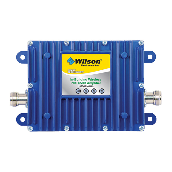
Wilson Electronics 801306 Installation Manual
In-building
wireless pcs
smart technology amplifier
Hide thumbs
Also See for 801306:
- Installation manual (16 pages) ,
- Installation manual (16 pages) ,
- Installation manual (16 pages)
Advertisement
PCS Smart Technology™ Amplifier
Installation Guide
Smart Technology
Wilson Electronics, Inc.
3301 E. Deseret Drive, St. George, Utah 84790
For additional technical support visit
www.wilsonelectronics.com
Phone: 1-866-294-1660
The term "IC:" before the radio certification number signifies
that Industry of Canada technical specifications were met.
In-Building
Wireless PCS
Amplifier
TM
PART # 801306
1850-1990 MHz
FCC ID: PWO8013SB
IC: 4726A-8013SB
Fax: 1-435-656-2432
Advertisement
Table of Contents

Summary of Contents for Wilson Electronics 801306
-
Page 1: Installation Guide
PCS Smart Technology™ Amplifier Installation Guide In-Building Wireless PCS Smart Technology Amplifier PART # 801306 1850-1990 MHz FCC ID: PWO8013SB IC: 4726A-8013SB Wilson Electronics, Inc. 3301 E. Deseret Drive, St. George, Utah 84790 For additional technical support visit www.wilsonelectronics.com Phone: 1-866-294-1660 Fax: 1-435-656-2432 The term “IC:”... -
Page 2: Package Contents
1. PURPOSE OF THE AMPLIFIER The PCS Smart Technology Amplifier improves RF coverage for areas in which low signal strength is a concern. 2. PACKAGE CONTENTS 2.1 Amplifier 2.2 AC/DC 110 volt Power Supply 3. HOW THE AMPLIFIER FUNCTIONS The signal is received by the outside antenna from the cell site. The signal is then AMPLIFIED and transmitted to your phone through the inside antenna. - Page 3 4.3 Indicator Lights ALL LIGHTS GREEN = 60 dB GAIN LIGHT D OFF = 2 dB REDUCTION LIGHT D & C OFF = 10 dB REDUCTION LIGHT D, C & B OFF = 20 dB REDUCTION LIGHT A = 40 dB REDUCTION 4.4 Installing The Wilson Cellular Inside Antenna 4.4.1 See antenna packaging for model specific instructions.
- Page 4 Outside Antenna 1900 MHz Yagi Antenna Shown Cell Site Amplifier Outside Antenna to Inside Antenna to Amplifier Connection Amplifier Connection AC / DC Power Supply Supports Multiple Users If using a Yagi Antenna, Make sure the Yagi is not pointed toward the inside antenna.
-
Page 5: Amplifier Specifications
AMPLIFIER LAYOUT DIAGRAM For maximum gain, keep a separation distance of at least 50 feet between the outside and inside antennas. 5. AMPLIFIER SPECIFICATIONS Part Number 801306 Inside Antenna Gain 60 dB Optional Dome Antenna Shown Frequency 1850-1910 MHz / 1930-1990 MHz... -
Page 6: Tech Support
The information provided by Wilson Electronics, Inc. is believed to be complete and accurate. However, no respon- sibility is assumed by Wilson Electronics, Inc. for any business or personal losses arising from its use, or for any infringements of patents or other rights of third parties that may result from its use. - Page 7 EXTENSION CABLE CHART 951110 2’ Extension Cable RG58U Used with the Yagi antenna to help find the Low Loss Coax optimum signal strength (for installation purposes N-Male to FME-Female only). 951101 5’ Extension Cable RG58U 0.6 dB loss Low Loss Coax 951102 10’...
- Page 8 1900 MHz Yagi Optional Accessories Dome Dual Polarity FME Male to Dome N-Male Lightning Suppressor Panel Coax Cable Extension Ultra Low Loss Coax Mini Magnet Trucker 3/8" Magnet Profile Mount Mount 1 YEAR WARRANTY 15 DAY The Wilson amplifier is warranted for one year against defects in workmanship MONEY BACK and/or materials and will be repaired or replaced, at the discretion of the manufac- GUARANTEE...


Need help?
Do you have a question about the 801306 and is the answer not in the manual?
Questions and answers