Advertisement
Installation Guide
Cellular & PCS
Analog & Digital - CDMA, GPRS, GSM, TDMA, 1x, HSDPA
Mobile Wireless
Dual Band
Cellular/PCS
TM
Smart Technology
Amplifi er
PART# 801201-A
FCC ID: PWO8012ASM
IC: 4726A-8012ASM
Wilson Electronics, Inc.
3301 E. Deseret Drive, St. George, Utah 84790
For additional technical support go to
www.wilsonelectronics.com
Phone: 1-866-294-1660
Fax: 1-435-656-2432
The term "IC:" before the radio certification number signifies
that Industry of Canada technical specifications were met.
Advertisement
Table of Contents

Summary of Contents for Wilson Electronics Smart Technology 801201-A
- Page 1 Cellular/PCS Smart Technology Amplifi er PART# 801201-A FCC ID: PWO8012ASM IC: 4726A-8012ASM Wilson Electronics, Inc. 3301 E. Deseret Drive, St. George, Utah 84790 For additional technical support go to www.wilsonelectronics.com Phone: 1-866-294-1660 Fax: 1-435-656-2432 The term “IC:” before the radio certification number signifies...
-
Page 2: Package Contents
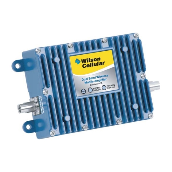
1. PURPOSE OF THE AMPLIFIER This Wilson Smart Technology™ Amplifi er greatly improves signal strength inside a vehicle without a physical connection to the phone or cellular data card. It also allows multiple devices to be used simultaneously. 2. PACKAGE CONTENTS PACKAGE CONTENTS •... - Page 3 Wilson Cellular 4.2 Installing the Inside Antenna (2 options included) 4.2.1A (option A) - The inside antenna should be mounted approximately 1 foot or less from where the phone is used. The best place to mount the inside antenna is shoulder height on the side of the drivers seat.
- Page 4 Wilson Cellular 4.3 Installing the Outside Antenna (Sold Separately) 4.3.1 Select an outside mounting location. For best performance keep the antenna centered on the vehicle’s roof. 4.3.2 The outside antenna should be located in an area with at least a 12” radius clear of obstructions, and other radiating elements.
-
Page 5: Amplifier Specifications
MOBILE AMPLIFIER LAYOUT Outside Antenna Cell Site Cell Phone(s) Inside Antenna Power Amplifier Supply 5. AMPLIFIER SPECIFICATIONS Dual Band 800 / 1900 MHz Part Number 801201-A Connectors FME-Male 50 Ohms Dimensions 5.6 x 3.6 x 1.7 inch or 14.2 x 9.1 x 4.4 cm Weight 1.44 lbs or 0.65 kg Frequency... -
Page 6: Tech Support
Our Hours of Operation are: 8:00 AM – 4:30 PM (Mountain Time) The information provided by Wilson Electronics, Inc. is believed to be complete and accurate. However, no responsibility is assumed by Wilson Electronics, Inc. for any business or per- sonal losses arising from its use, or for any infringements of patents or other rights of third parties that may result from its use. -
Page 7: Notes And Warnings
9. NOTES & WARNINGS WARNING: Verify that both the outside antenna and the inside antenna are connected before powering up the amplifi er. WARNING: Do not place the outside antenna in the vehicle without turning the amplifi er off. For example, when at a car wash. - Page 8 This device has been designed to operate with the antennas listed below, and having a maximum gain of 6.12 dB. Antennas not included in this list or having a gain greater than 6.12 dB are strictly prohibited for use with this device. The required antenna impedance is 50 ohms.


Need help?
Do you have a question about the Smart Technology 801201-A and is the answer not in the manual?
Questions and answers