Table of Contents
Advertisement
Quick Links
Advertisement
Table of Contents

Related Manuals for Samwon Tech Temp 2000 M


Summary of Contents for Samwon Tech Temp 2000 M
- Page 1 Instruction Manual...
-
Page 2: Table Of Contents
SAMWONTECH ※ This edition is common manual for TEMP2500M, TEMP2700M. Contents Manipulation Safety instruction (Cautions) Checking the product····················································································· Exterior and how to install··············································································· Wiring ····································································································· Display function and name·············································································· Control part LED ···················································································· Manipulation and setting Basic operation flow chart··············································································· Setting button operation ·················································································... - Page 3 SAMWONTECH Pattern graph display ····················································································· Measured data (PV) graph view········································································· Setting the measure data (PV) graph saving ························································· SD memory storage setting ············································································· Screen display setting Screen display setting····················································································· DI error occurrence history view········································································ Heater short state·························································································· Time setting ····································································································· Communication error ··························································································...
- Page 4 SAMWONTECH 16.2 ON/OFF signal operation ················································································ 17. Alarming signal 17.1 Alarming signal setting ··················································································· 17.2 Alarming signal operation ··············································································· 17.3 Heater short alarming signal ·········································································· 18. PID Group 18.1 PID application scope setting··········································································· 18.2 PID group setting ························································································· 19. DI function and operation 19.1 DI operation setting ······················································································...
-
Page 5: Manipulation
SAMWONTECH 1. Safety instruction (Cautions) Thank you for your choice our multi channel programmable controller (TEMP2000M). This installation manual describes how to install this product. Safety symbol mark (A) “Handle with care” or “Caution” shall be expressed. In case of violation of this point, it may cause the death, heavy injury or severe damage on the device. - Page 6 SAMWONTECH 음Safety and cautions in the modification(Change)음 음on the product (Change) on the product음 (A) Use this product after full understanding on the cautions (Instructions) for the safety in auto tuning for the protection and safety of the product of the system to be connected for use. (B) Our company is not responsible for the use and handling and every loss incurred due to the negligence without following auto tuning.
-
Page 7: Checking The Product
SAMWONTECH 1.1 Checking the product ▶ Check whether there is no damage on the product by inspecting on the exterior when the product is accepted. In addition, check the following points. 1.1.1 Check the specification of the ordered product ▶ Check whether the accepted product is same with the ordered specification. How to check: Check the model name specification code on the right of packing box and label on the left of product case. - Page 8 SAMWONTECH 1.1.2 Check the packing contents ▶ Check whether the following contents are contained. TEMP2000M_SERIES TEMP2000M_SERIES TEMP2000M_SERIES I/O1 BOARD Main body – display part CONTROL PART-Main CONTROL PART-Sub SD CARD I/O2 BOARD Cable (1m) Cable (2m) Cable (3m) (In case of (In case of Fixing mount End bar...
- Page 9 SAMWONTECH 1.1.3 Processing of the damaged product ▶ Contact to the point of product purchase or sales department of our company when the product is damaged at the external inspection on the product as in the above or omission of the parts. Exchange period for the parts with life span ▶...
-
Page 10: Exterior And How To Install
SAMWONTECH 1.2 Exterior and how to install 1.2.1 Installation location and environment ACautions in installation location and environment (A) Handle after switching on at the state of installing this product on the panel because there is a risk of electric shocking. (Cautions for electric shocking) Do not install this product at the following location and environment. - Page 11 SAMWONTECH 1.2.2 External dimension (Unit: mm) 1.2.2.1 External dimension of display part for each model Unit : mm Model Name TEMP2500M 33.5 136.5 136.5 TEMP2700M 38.2 172.5 195.5 1.2.2.2 External dimension of control part 100.8 100.8 25.5 Main unit Sub unit 2nd Edition of TEMP2000M_Series IM : April.
- Page 12 SAMWONTECH 1.2.2.3 I/O1 BOARD external dimension 1.2.2.4 I/O2 BOARD external dimension 1.2.3 Panel cutting dimension ▶ In case of general attaching ※ Panel cutting dimension for each model Unit: mm MODEL TEMP2500M 137.5 137.5 TEMP2700M 308.5 2nd Edition of TEMP2000M_Series IM : April. 8. 2014 Page 8 / 176...
- Page 13 SAMWONTECH 1.2.4 How to attach mount 1.2.4.1 How to install display part ▶ TEMP2000M DISPLAY UNIT panel installation method Fixing Phillips screwdriver Insert Panel thickness: DISPL The installation of fixing mount on 2~7mm the left, right, upper and lower part of display doesn’t matter.
- Page 14 SAMWONTECH 1.2.4.2 How to install control part ▶ In case of installing DIN rail 1) DIN rail preparation 2) Insert the ⓐ part on the main unit and sub unit into the rail first as shown in the picture and push ⓑ...
- Page 15 SAMWONTECH 4) Both ends of unit is fixed with end bar when the main and sub units are installed not be moved. End bar How to assemble the end bar Firstly insert the end bar on Push up the end bar to Fasten the screw.
- Page 16 SAMWONTECH ▶ In case of installing on the wall directly, 1) Disassemble the back cover of main and sub unit as follows. Sub unit Main unit Sub unit Main unit Back cover Back cover ① pushing ① Pushing ② Pulling ②...
- Page 17 SAMWONTECH 3) Assemble back cover and fix on the wall with screw. M3X12 Fastening torque recommended for screw Main unit Sub unit 0.3 N∙m(3㎏f∙㎝) BACK COVER BACK COVER ▪ Be cautious for the foreign material not to be put into the connector in case of fixing the back cover on the wall.
- Page 18 SAMWONTECH 5) Fix by inserting the fixing unit for each unit not to be separated as shown in the figure. Fixing unit 2nd Edition of TEMP2000M_Series IM : April. 8. 2014 Page 14 / 176...
-
Page 19: Wiring
SAMWONTECH 1.3 Wiring Cautions ▶ Switch off the main power of every supplied gauge and wire after checking with the tester whether the electric power on the wiring cable is on. ▶ Do not contact with the terminal absolutely because there is a possibility of electricity after switching on. - Page 20 SAMWONTECH 1.3.2 Terminal layout 1.3.2.2 TEMP2000M display part terminal Electric power (24V DC) COM1 Connect display part and connection part to PC (Ethernet) Ethernet COM1 Display part, control part and connection part COM2 Display part and PCconnection part (RS485) 1.3.2.3 Control part terminal HBA1, 2 COM1 Display...
- Page 21 SAMWONTECH 1.3.2.4 I/O1 BOARD terminal Electric power I/O1 LINK (24V DC) Communication terminal DI10 DI11 DI12 DI13 DI14 DI15 DI16 RLY12 RLY11 RLY10 RLY9 RLY8 RLY7 RLY6 RLY5 RLY4 RLY3 RLY2 RLY1 RLY12 RLY11 RLY10 RLY9 1.3.2.5 I/O2 BOARD terminal RLY27 RLY28 RLY29 RLY30 RLY31 RLY32 I/O2 LINK RLY26 RLY25 RLY24 RLY23 RLY22 RLY21 RLY20 RLY19 RLY18 RLY17 RLY16 RLY15 RLY14 RLY13...
- Page 22 SAMWONTECH 1.3.3 Electric power wiring ▶ For electric power cable, make wiring using the cable with equivalent performance of vinyl insulation cable (KSC 3304). ☞ Wiring method for electric power of each unit Communicati on cable (MP0310AS) 24V DC(+) 24V DC(-) Communicati on cable (MP0310AS)
- Page 23 SAMWONTECH Wiring method for electric power control unit of each unit 24V DC 1.3.3.1 Measured input (ANALOG INPUT) wiring ▶ Switch off the electric power and external power supply on the main body of TEMP2000M certainly in case of wiring the measurement input because there is a risk of electric shock. ▶...
- Page 24 SAMWONTECH 1.3.3.2 Control output (ANALOG OUTPUT) wiring ▶ Connect using caution for the output polarity. The wrong connection becomes a reason of the main body. ▶ Use the shield attached cable for output wiring. In addition, make one point connection for the shield. (A) Electric voltage pulse output (SSR) SHIELD Control panel...
- Page 25 SAMWONTECH 1.3.3.3 3 Output (Relay) wiring for external connection point ▶ Please switch off the electric power and power supply to outside from the TEMP2000M main body certainly in case of wiring the external contact point output because there is an electric shock risk. ▶...
- Page 26 SAMWONTECH 1.3.3.5 Use of sub relay ▶ ON/OFF the load with use of sub relay in case that the resistance load exceeds the relay specification. ▶ In case of using the inductance (L) load such as the sub relay and solenoid valve, insert the CR filter (In using AC) or diode (In using DC) by constituting the surge suppressor circuit for spark removing certainly because it becomes a reason for mal operation and relay failure.
- Page 27 SAMWONTECH 1.3.3.7 Display part communication wiring method 15 ~ 20 mm (Minimum marginal dimension in case of cable connection) 2nd Edition of TEMP2000M_Series IM : April. 8. 2014 Page 23 / 176...
-
Page 28: Display Function And Name
SAMWONTECH 1.4 Display function and name ▶ TEMP2000M display part ④ ⑤ ③ ② ⑥ ① ① Cover (When the cover is opened, the electric power switch, inserting part of SD card and mini USB connection part are displayed.) ② TEMP2000M display part electric power switch ③... -
Page 29: Control Part Led
SAMWONTECH 1.5 Control part LED ▶ COM1 LED blinks when the communication between display part and control part are connected. ▶ COM2 LED blinks when the communication between control part and I/O1 board is connected. ▶ MV LED blinks depending on the control output for temperature. (A) Main unit LED displaying the communication Main output display LED... -
Page 30: Manipulation And Setting
SAMWONTECH 2. Manipulation and setting ▶ This produce is composed of dialogue style screen in touch screen method and it is a programmable controller designed easy for use by the customer. 2.1 Basic operation flow chart ▶ When the electric power is ON after the installation of the product, the initial screen is displayed sequentially and it converts to the program stop screen automatically. -
Page 31: Setting Button Operation
SAMWONTECH 2.2 Setting button operation ▶ Basic setting buttons are shown in [Table 2-1]. Table 2-1. Basic setting button Button type Button operation Touch the ‘Setting Data” in the stationary stop/operation screen and it is used for setting the wanted setting data by the user. The “Pattern No.”... -
Page 32: How To Set The Parameters
SAMWONTECH 2.3 How to set the parameters ▶ The following setting data input key is displayed and the necessary data can be input when the clicked at the basic setting button in the above [Table 2-1] ▶ The error message (“LIMIT ERROR”) is appeared on the input data display window with error sound (”Beep”) when the data out of the setting range is input. - Page 33 SAMWONTECH ⑤ User tag input key ⑥ Display in case out of the setting range Touch key lock release ▶ Input after in OFF (Lock release state) of “Key lock” because the setting data is not input when the “Key lock” is “ON (Locked state) A.
- Page 34 SAMWONTECH 2.3.2 Setting data input method. ▶ The input data used in product is set by the setting data input key, test name input key and time signal input. ▶ When button in [Table 2-1] is pressed, the setting data input key is appeared, the data to be set can be input.
-
Page 35: Setting Operation State
SAMWONTECH 3. Setting operation state 3.1 Main screen ① ③ ② ⑤ ④ ⑥ [그림 3-1] 메인화면 Instruction Description It moves to the screen to set the use/non-use of the graph display, graph ① Graph & Storage recording and SD recording use. ②... -
Page 36: Stationary (Fix) Operation
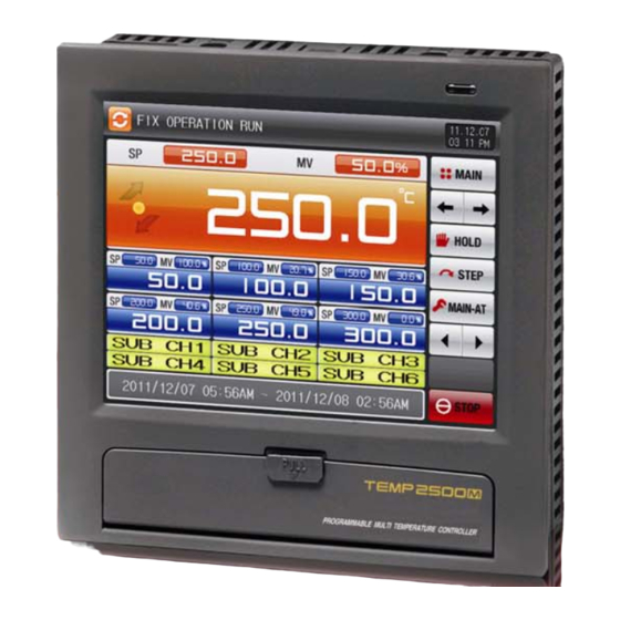
SAMWONTECH 3.2 Stationary (FIX) operation 3.2.1 Stationary operation the 1 still scree ▶ Select the operation method in “Stationary” in [4. Operation related motion setting]. ▶ When “Operation state screen” is selected in [3.1 Main screen], it converts to “Stationary operation the still screen.”... - Page 37 SAMWONTECH 3.2.2 Stationary operation the 1 operation screen ▶ It is the screen for measured data, setting data, control output quantity and lamp operation state. ▶ The setting data input key is displayed when the “Setting data” is touched during operation. ⑧...
- Page 38 SAMWONTECH ① [Fig 3-5] Stationary operation the 1 operation screen -2 ① t displays the user tag. ☞ The setting for the user tag and name can be set in [7.1 Screen display setting]. ▶ It is the operation screen in case of 2, 4 sub channels. [Fig.
- Page 39 SAMWONTECH 3.2.3 Stationary operation the 2 operation screen ▶ ( ) Check box sets the display for Y/N of the data. ▶ The data stored in the internal memory is erased when the electric power is OFF. ☞ Save the important graph file with SD card. ☞...
- Page 40 SAMWONTECH 3.2.4 Stationary operation still screen ▶ The stationary operation is terminated while the “Time setting operation is terminated” is appeared as shown in the following screen when the operation is stopped by passing the setting time in [4. Operation related motion setting].
-
Page 41: Program Operation
SAMWONTECH 3.3 Program operation 3.3.1 Program operation the 1 still screen ▶ Select the operation method of “Pattern” in [4. Operation related motion setting]. ▶ When “Operation state screen” is selected in [3.1 Main screen], it converts to “Stationary operation the still screen.”... - Page 42 SAMWONTECH 3.3.2 Program operation the 1 still screen ▶ It is the screen for measured data, setting data, control output quantity and operation state. ▶ The pattern No. cannot be set during operation. ① ⑨ ② ⑩ ⑪ ③ ④ ⑤...
- Page 43 SAMWONTECH ▶ It is the screen for measured data, setting data, control output quantity and sub channel tag name. ▶ The pattern No. cannot be set during operation. ① ② ③ ④ ⑥ ⑤ [Fig. 3-14] Program operation the 1 operation screen -3 ①...
- Page 44 SAMWONTECH 3.3.3 Program operation the 2 operation screen ▶ The left side of the screen displays the measurement data, setting data and control output quantity ▶ ( ) Check box sets the display for Y/N of the data. ▶ Press the (Saving) button on the middle of the right to save the data recording the button into the internal memory.
- Page 45 SAMWONTECH 3.3.4 Program operation still screen ▶ The program operation is terminated while the “Program operation is terminated” is appeared as shown in the following screen when the setting range operation is stopped in every segment saved into the pattern. ▶...
-
Page 46: Auto Tuning Screen
SAMWONTECH 3.4 Auto tuning screen ▶ The auto tuning method is categorized into SEG PID type and zone PID type. ▶ The auto tuning hold and step key cannot be used during program operation. 3.4.1 Auto tuning (SEG PID type) ▶... - Page 47 SAMWONTECH ▶ FIX and PROGRAM: AUTO TUNING(SEG) ☞ INRH, INRL : Indicates input sensor range. ☞ Threshold 1 ~4: Indicates threshold value of PID No. ☞ Auto Tuning : Indicates PID No selected for Auto Tuning. ☞ Auto Tuning Set Point: Indicates currently running Set Point. FIX OPERATION: AUTO TUNING (SEG) INRH 1000...
- Page 48 SAMWONTECH 3.4.2 Auto tuning (Zone PID type) ▶ The tuning is made with the target of the center point of boundary data in PID No. group set in auto tuning parameter and the tuning data is saved into the set PID No. ▶...
- Page 49 SAMWONTECH ▶ FIX and PROGRAM: AUTO TUNING (Zone) ☞ INRH, INRL : Indicates input sensor range. ☞ Threshold 1 ~4: Indicates threshold value of PID No. ☞ Auto Tuning : Indicates PID No selected for Auto Tuning. ☞ Auto Tuning Set Point: Indicates currently running Set Point. FIX OPERATION: AUTO TUNING (Zone) PROGRAM OPERATION: AUTO TUNING (Zone) 2nd Edition of TEMP2000M_Series IM : April.
- Page 50 SAMWONTECH ▶ Tuning point calculation in zone type shall be made as follows. ① Tuning point : 1 ☞ PID1 range auto tuning is performed. Lower limit Boundary data1 – Lower limit range - PID1 auto tuning setting data= range + ②...
-
Page 51: Sub Channel Auto Tuning
SAMWONTECH 3.5 Sub channel auto tuning ▶ It is a screen for auto tuning of the sub channel. ▶ The sub channel processes the tuning with set SP. ① ② [Fig. 3-19] Screen set with sub 2 tuning ① The auto tuning is performed or released with current setting data. . ②... -
Page 52: Auto Tuning And Tuning Point
SAMWONTECH 3.6 AUTO TUNING and TUNING POINT ▶ Auto-Tuning is a strong function to establish optimal P.I.D value automatically by calculating the characteristics of the control system. ▶ While generating ON/OFF control output signal for 2.5 cycles, the controller measures the PV response of the control system with a limit cycle method and calculate the optimal P.I.D value with the oscillation data. -
Page 53: Operation Related Motion Setting
SAMWONTECH 4. Operation related motion setting 4.1 Operation method setting ▶ It is a screen for the additional function of the general device and the additional installation in stationary operation. ① ⑤ ② ③ ⑥ ④ ⑦ [Fig. 4-1] Screen for setting operation related motion ①... - Page 54 SAMWONTECH 표 4-1. Operation related motion parameter Parameter Setting range Unit Initial value Operation method Pattern, Stationary Pattern Recovery motion in Stop, Restart, Continue Stop blackout Fuzzy function No motion, Motion No motion SETTING DATA EUS(0.00 ~ 100.00%) / MIN EUS / MIN EUS(0.00%) /MIN change ratio...
-
Page 55: Fuzzy Operation
SAMWONTECH 4.2 FUZZY function ▶ FUZZY function can effectively control the overshoot that may occur when intense fluctuating load or frequent Set Point changing. ▶ Before PV approaches to SP, automatically calculated SUPER SP can restrain overshoot. ▪ FUZZY ‘OFF’ Time ▪... -
Page 56: Setting Data Change Ratio (Slope) Operation
SAMWONTECH 4.3 SP SLOPE function ▶ SP SLOPE function to make the Set Point ascend or descent gradually overtime. ▶ When changing the Target SP during FIX run operation, NSP (current SP) will be changed from current PV to Target SP gradually by assigned ramping rate. ▶... -
Page 57: Program Setting
SAMWONTECH 5. Program setting ▶ When program setting button is pressed in [3.1 Main screen], it is converted to [Fig. 5-1 Program setting screen]. ▶ It is a screen group to set the parameter related with program operation. ① ③ ②... -
Page 58: Program Pattern Setting
SAMWONTECH 5.1 Program pattern setting ▶ It is a screen to set the segment according to the pattern No. ▶ Refer to the time signal setting [5.4 Time signal motion] for time signal setting. ① ② ⑧ ⑨ ③ ④ ⑤... - Page 59 SAMWONTECH PROGRAM RUN START ▶ PROGRAM OPERARTION START is done according to the setting of STC (START CODE) setup. (1) Setting Point Preferred Program Operation (STC = SSP) ▶ When program operation starts, SP starts from SSP and operates until SP1 under 1SEG for set Time 1(TM1).
- Page 60 SAMWONTECH ④ When there is only rising section without maintaining section. Program Present Pointing Value Operation Start Operation Not started E(SSP) Segment ⑤ When maintaining section starts from Segment 1. Present Program Pointing Value Operation Start A(SSP) Segment (3) Time Preferred Program Operation (STC = T.PV) ▶...
- Page 61 SAMWONTECH ▶ It is the screen for sub output setting screen. ▶ Select sub output in [12.1 Control&Transmitting output]. ▶ It is expressed in red in pattern editing screen and the sub output can be set. ▶ When the “Pattern No.” is touched in the screen, the input key is displayed for pattern number input. ▶...
- Page 62 SAMWONTECH ▶ It is the screen for the start condition with “SPV.” ▶ It is the screen for the start condition with “SSP.”. ▶ When this is inactivated, (Insertion), (Deletion) button are activated. 2nd Edition of TEMP2000M_Series IM : April. 8. 2014 Page 58 / 176...
- Page 63 SAMWONTECH ▶ When setting data button is pressed, the input key is displayed to set the setting data. ▶ When (time) button is pressed, the input to set the segment operation time is displayed. ▶ When (time signal) button is pressed, the input to set the time signal is displayed. ▶...
- Page 64 SAMWONTECH ▶ When (SEG alarming) button is pressed, the input key to set the SEG alarming is displayed. ▶ When (SEG PID) button is pressed, the input key to set the SEG PID is displayed. ▶ Input the time signal and SEG alarming by pressing (ENTER) button.
-
Page 65: Pattern Repetition Setting
SAMWONTECH 5.2 Pattern repetition setting ▶ It is a screen to set the function for the entire set pattern or partial repetition. ▶ In addition, the motion can be set in pattern operation termination. ① ⑦ ② ③ ⑧ ④ ⑤... -
Page 66: File Editing
SAMWONTECH 5.3 File editing ▶ It is a screen to copy or delete the segment data input to the pattern in [5.1 Program pattern setting]. ▶ The pattern No. under operation cannot be deleted. ▶ The deleted pattern cannot be recovered. ①... - Page 67 SAMWONTECH ▶ When the copy and deletion are made by wrong input of the pattern No., the message like “It is the parameter setting mistake.” Is displayed at the bottom of the screen. [Fig. 5-5] File editing screen-2 Table 5-3. File editing parameter Parameter Setting range Unit...
-
Page 68: Time Signal Operation
SAMWONTECH 5.4 Time signal operation ▶ The time signal motion is classified into ON/OFF Motion, time setting motion and the set time signal is used for time signal No. setting in the segment setting of [5.1 Program pattern setting]. 5.4.1 Time signal ON/OFF Motion ①... - Page 69 SAMWONTECH [Fig. 5-8] Time signal setting the 3 screen ① ② [Fig. 5-9] Time signal setting the 4 screen ① The time signal is ON after the setting time from the corresponding segment starting point till the delayed time. ☞ However, the time sign is not ON when the delay time is bigger than corresponding segment time. ②...
- Page 70 SAMWONTECH 5.4.3 Examples of operation when the input time signal Setting Time signal operation Operation time 1. Delay time = 000.00.00 Time signal 2 setting data N SEG TIME SEGMENT (N-1) SEG TIME N SEG TIME (N+1) SEG TIME ≥ Delay time + Operation time Operation time...
-
Page 71: Standby Operation
SAMWONTECH 5.5 Standby operation ▶ It is a screen to set the standby range and time to standby during program operation ▶ The set standby operation here is applied to [5.1 Program pattern setting]. ※ Definition on standby operation Condition for entering the standby operation ... - Page 72 SAMWONTECH ▶ The relation between s1 and standby time is as follows. ▶ S1 scope : It displays the standby operation range. ① Release WAIT Operation within WAIT TIME Wait Time Set Point Wait Zone Wait Zone Release WAIT Operation WAIT Operation Step to the next Segment (Actual Delay Time)
-
Page 73: Experiment Name Setting
SAMWONTECH 5.6 Experiment name setting ▶ The experiment name can be set to each pattern. ▶ Refer to [3.3.2 Program operation the 1 operation screen]. ① ② [Fig. 5-11] Experiment name setting screen ① The experiment name of each pattern can be input. ②... -
Page 74: Graph Display And Saving Setting
SAMWONTECH 6. Graph display and saving setting 6.1 Pattern graph display ▶ This screen displays the operation pattern and process time with graph during program operation. ▶ It converts to the 1 screen (Pattern graph display)] when [Graph & Save] is selected at the upper left of [Fig. - Page 75 SAMWONTECH ⑤ When the (Left/Right) button is pressed at present page, it changes into the previous/next stage on the time axis. ▶ It is a screen to display the process time of the segment. ① ② ③ [Fig. 6-3] Graph & Save the 1 screen (Program operation) ①...
-
Page 76: Measured Data (Pv) Graph View
SAMWONTECH 6.2 Measured data (PV) graph view ▶ It is a screen to display by opening the data file recorded in [3.2.3 Stationary operation the 2 operation screen] and [3.3.3 Program the 2 operation screen]. ▶ The date and time stored in the internal memory is displayed on the top of the screen. ②... - Page 77 SAMWONTECH ▶ It is a screen to display the saved file into the internal memory. ▶ Refer to [3.2.3 Stationary operation the 2 operation screen] and [3.3.3 Program operation the 2 operation screen] for saving into internal memory. . ② ①...
-
Page 78: Setting The Measure Data (Pv) Graph Saving
SAMWONTECH 6.3 Setting the measure data (PV) graph saving ▶ It is a screen to set the display range and sampling time in [3.2.3 Stationary operation the 2 operation screen] and [3.3.3 Program operation the 2 operation screen]. ① ② ③... - Page 79 SAMWONTECH ▶ It is a screen to set the pen using on the PV graph. ▶ It can set up to Pen 6. ① ② ④ ③ ⑤ [Fig. 6-9] Graph & Save setting the 4 screen-1 ⑦ ⑥ [Fig. 6-10] Graph & Save setting the 4 screen-2 ①...
-
Page 80: Sd Memory Storage Setting
SAMWONTECH 6.4 SD memory storage setting ▶ It is a set the necessary item in data backup on SD card. ☞ It is a screen to display only in SD card option. ① ② ③ [Fig 6-11] Graph & Save setting the 5 screen ①... -
Page 81: Screen Display Setting
SAMWONTECH 7. Screen display setting 7.1 Screen display setting ▶ It is a screen to set the font and to control the screen brightness to be displayed in operation screen. ④ ① ⑤ ② ③ [Fig. 7-1] Screen display setting the 1 screen ①... - Page 82 SAMWONTECH ▶ It is a screen to set the user tag name. [그림 7-2] Setting of user tag name screen 표 7-1. Display set the 1 parameter Parameter Setting range Unit Initial data Buzzer sound Non-use, Use Power saving operation time 0 ~ 99 MIN LED brightness 1 ~ 8...
-
Page 83: Di Error Occurrence History View
SAMWONTECH 7.2 DI error occurrence history view ▶ It is a screen to display the DI type, date and time where the error is created. ▶ Maximum 30 error history is displayed. ☞ The earliest numbers out of the displayed errors are deleted when more than 30 errors are created and the created errors are added at the end. - Page 84 SAMWONTECH ▶ It is a screen for DI error creation. ▶ The character and photo screen setting can be made in [19. DI function and operation setting]. ▶ When (Recovery) button is pressed, it is converted to the operation screen by escaping from DI error screen.
-
Page 85: Heater Short State
SAMWONTECH 7.3 Heater disconnection state ▶ It is a screen to display the heater disconnection creation. ① ④ ② ③ [Fig. 7-4] Heater disconnection state creation ① When the heater is disconnected which is connected to the main and sub channel, it is changed into ②... -
Page 86: Time Setting
SAMWONTECH 8. Time setting ▶ It is a screen to set the current time and operation appointment time. ③ ① ② [Fig. 8-1] Time setting screen ① It sets the year, month, day and time. ☞ The present time cannot be changed during the recording of the measured data and operation. ②... - Page 87 SAMWONTECH Table 8-1. Appointment operation setting parameter Parameter Setting range Unit Initial data Year 2000~2099 Month 1~12 1~31 Present time AM/PM AM, PM Hour 1~12 Minute 0~59 Year 2000~2099 2011 Month 1~12 Appointed 1~31 operation AM/PM AM, PM time Hour 1~12 Minute 0~59...
-
Page 88: Communication Error
SAMWONTECH 9. Communication error ▶ When communication between display and control unit is wrong, the message like the “Control part was disconnected” is displayed in [Fig. 9-1 Control Unit Communication error screen]. ▶ When communication between display and I/O board communication is wrong, the message like “I/O board was disconnected”... -
Page 89: System Setting
SAMWONTECH 10. System setting 10.1 Main screen ▶ The basic screen is as follows. ① ② [Fig. 10-1] Main screen ▶ When ① and ② in [Fig. 10-1 Main screen] are pressed in sequence, the screen [Fig. 10-2 Password input screen] is displayed. ▶... - Page 90 SAMWONTECH ▶ The system parameter setting screen is as follows. [Fig. 10-3] System parameter setting screen SYMBOL Item Function Remarks Parameter setting related with input sensor type and Input set sensor input Output set Parameter setting related with output type and output Inner signal Parameter setting related with inner signal ON/OFF signal...
-
Page 91: System Parameter Setting Procedure
SAMWONTECH 10.2 System parameter setting procedure ▶ The system parameter setting procedures which shall be preferentially treated in product installation are as follows. Setting SYMBOL Item Function Remarks sequence ① Temperature sensor type setting Input set ② Sensor use scope setting PAGE 88 ③... -
Page 92: Sensor Input
SAMWONTECH 11. Sensor input 11.1 Sensor input setting 11.1.1 Sensor input the 1 screen ▶ Temperature (T/C, RTD, DCV) sensor is selected. ☞ The sensor setting shall be set at first certainly. ⑤ ⑥ ① ⑦ ⑧ ② ⑨ ③ ⑩... - Page 93 SAMWONTECH [Fig. 11-2] Sensor type setting screen (In case of T/C setting) [Fig. 11-3] Display unit setting screen (In case of T/C, RTD setting) ▶ When the temperature sensor is set in RTD, the following screen is displayed.) [Fig. 11-4] Sensor input setting the 1 screen (In case of RTD setting.) 2nd Edition of TEMP2000M_Series IM : April.
- Page 94 SAMWONTECH ▶ One of the 6 sensor types can be selected. [Fig. 11-5] Sensor type setting screen (In case of RTD setting.) ▶ When the temperature sensor is set in DCV, the following screen is displayed. ② ③ ① [Fig. 11-6] Sensor input setting the 1 screen (In case of DVC setting.) ①...
- Page 95 SAMWONTECH ▶ One of five sensor types can be selected. [Fig. 11-7] Sensor type setting screen (In case of DCV setting.) ▶ One of 12 units can be selected and used. [Fig. 11-8] Display unit setting screen (In case of DCV setting.) 2nd Edition of TEMP2000M_Series IM : April.
- Page 96 SAMWONTECH ▶ It is a screen to select the place of decimal point. [Fig. 11-9] Decimal point setting screen (In case of DCV setting) Table 11-1. Sensor input setting the 1 screen parameter Parameter Setting range Unit Initial data Sensor group T/C, RTD, DCV TC-K1, TC-K2, TC-J, TC-E, TC-T, TC-R, TC-B, TC-S, TC-L,...
- Page 97 SAMWONTECH 11.1.2 Sensor input the 2 screen ▶ It calibrates the temperature range input. ▶ The range calibration is applied in the form of the equation of the first between the calibration points. ④ ① ② ③ [Fig. 11-10] Sensor input calibration screen for each range ①...
-
Page 98: Sectional Input Calibration Setting
SAMWONTECH 11.3 PIECE BIAS setting ▶ It displays Section Input Compensation. ▶ It explains for CH1, and CH2 is same as CH1. Sensor measurements ⑧ ⑧ After calibration, the current indicated value ⑦ ⑥ ⑤ ④ ② ③ ① INRH ①... - Page 99 SAMWONTECH ⑤ Compensated Temperature between Input Comp. 4 ~ Input Comp. 5 Section = Actual Sensor Temperature + (Actual Sensor Temperature – Input Comp. Point 4) X (Input Comp. 5 Value – Input Comp. 4 Value) + Input Comp. 4 Value (Input Comp.
-
Page 100: Control & Transmitting Output
SAMWONTECH 12. Control & Transmitting output 12.1 Control output setting 12.1.1 Output setting the 1 screen ▶ It sets the output type for temperature control. ① ③ ② ④ [Fig. 12-1] Control output setting the 1 screen ① It sets the output type of the OUT1 output terminal. ☞... - Page 101 SAMWONTECH ▶ It sets the type of output for temperature control. ▶ The following figure is the setting on the product. It is a screen to check/set with the graphics. ① ② ③ [Fig. 12-2] Output terminal displays screen ① When OUT1 is set in SSR at [Fig. 12-1 Output setting the 1 screen].
- Page 102 SAMWONTECH ▶ It is a screen to set the SCR output terminal, transmitting output and sub output. ▶ When the sub output is set, it can be set in [Fig. 5-2 Pattern editing screen]. [Fig. 12-4] SCR output terminal and transmitting output terminal setting screen Table 12-1.
- Page 103 SAMWONTECH 12.1.2 Output setting the 2 screen ▶ It sets control related parameter. ① ⑥ ⑦ ② ③ ④ ⑤ ⑧ [Fig. 12-5] Output setting the 2 screen ⑩ It sets the operation method of PID control. ☞ Refer to [12.1.2.1 Operation direction] ⑪...
- Page 104 SAMWONTECH 12.1.2.1 Operation Direction Control Output (MV) 100% Reverse Forward Control Output increase when PV is smaller Control Output increase when PV is bigger than SP. → Heating, Humidify than SP. → Cooling, Dehumidify Deviation (PV-SP) 12.1.2.2 Output Cycle ▶ Applies only when control output type is “SSR(Solid State Relay)”. ▶...
- Page 105 SAMWONTECH 12.1.2.3 Over-Integral Prevention ▶ It is one of efficient method to control when disturbance occurs. ☞ This function suppresses overshoot due to over-integral when control output reaches to max value. ▶ It does not work when I=0 at PID set value. ☞...
- Page 106 SAMWONTECH ◈ Example What is the P BAND when Input Range High(RH)= 100.0℃, Input Range Low (RL)= -100.0℃, Rate(P) = 10.0%, Over-Integral Prevent(ARW)= 200%? Answer) ① Input Range = RH – RL = 100.0℃ - (-100.0℃) = 200.0 ℃ ② Input Range x Rate(P) = 200.0℃ X 10.0% = 20.0℃ ③...
-
Page 107: Transmission Output Setting
SAMWONTECH 12.2 Transmission output setting 12.2.1 Output setting the 3 screen ▶ It is a screen for setting the type of transmitting output. ▶ Either PV or SP can be set for transmission output. ① ② [Fig. 12-6] Output setting the 3 screen (In case of PV, SP setting) ①... - Page 108 SAMWONTECH 12.2.2 Output by Retransmission Type ▶ Retransmission Output is 4~20mA. ▶ Attach 250Ω(Precision Resistor) between both Retransmission terminal when use 1~5V retransmission output. ☞ When Retransmission Type is “PV” or “SP” 4.0mA 12.0mA 20.0mA Range Low Range High (Range High+Range Low)/2 ☞...
-
Page 109: Do Relay Output
SAMWONTECH 13. DO relay output 13.1 Relay No. and parameter setting ▶ When the state created during operation is output to the I/O relay board, the relay No. corresponding state is set. ▶ Relay No. 13 ~ 32 can be used for I/O2 BOARD option addition. 13.1.1 Inner signal/Time signal relay setting screen ▶... - Page 110 SAMWONTECH 13.1.2 Alarm signal/SEG alarm signal relay setting screen ① ② [Fig. 13-2] Alarm signal/SEG alarm signal relay setting screen ① It sets the alarm signal relay. (AL1∼AL4) ② It sets SEG Alarm signal relay. (SEG AL1∼SEG AL4) Table 13-2. Alarm signal/SEG alarm signal relay setting screen parameter Parameter Setting range Unit...
- Page 111 SAMWONTECH 13.1.3 ON/OFF signal relay setting screen ▶ It sets the relay No. for the ON/OFF signal and delay time for each ON/OFF signal. ▶ The set ON/OFF signal sends the actual contact point output after elapsing the set time for delay when the signal creation condition is made.
- Page 112 SAMWONTECH 13.1.4 DI signal relay setting screen ▶ It sets the relay No. for DI signal. ▶ DI signal send the contact point output to the set relay in case of DI error creation of corresponding No. ① [Fig. 13-4] signal relay setting screen ①...
- Page 113 SAMWONTECH 13.1.5 Manual signal/Arithmetic signal relay setting screen ▶ It sets the relay No. for the manual signal. ▶ It is used when the arbitrary relay is output with manual key or communication. ① ③ ② [Fig. 13-5] Manual signal setting screen ①...
- Page 114 SAMWONTECH ▶ It is a screen to set the arithmetic relay signal. ▶ The arithmetic signal can be set up to 3. ① ④ ③ ② ⑤ [Fig. 13-6] Manual signal setting screen ① It sets the output of arithmetic signal. ②...
-
Page 115: Other Signal Relay Setting
SAMWONTECH 13.2 Other signal relay setting 13.2.1 Other signal relay setting the 1 screen ▶ It is a screen to set the operation signal and sensor disconnection signal. ① ② ③ ⑤ ④ [Fig. 13-7] Other signal relay setting the 1 screen ①... - Page 116 SAMWONTECH - The stationary timer signal operation is calculated again in operation starting, changing the set value (SP), electric power “ON” (When it is set for immediate operation in electricity “ON” , recovery operation in black out or product is ON. ※...
- Page 117 SAMWONTECH ▶ It is a screen for other signal relay setting the 2 screen. ① ② ③ ④ [Fig. 13-8] Other signal relay setting the 2 screen ① It sets the ascending, descending signal relay and operation deviation. ☞ The state lamp of the operation screen and relay is operated at the same time. ☞...
- Page 118 SAMWONTECH ▶ It is a screen to set the operation termination signal and U-KEY relay. ▶ ① ② ③ [Fig. 13-8] Other signal relay setting the 3 screen ① Setting the stationary operation, program operation termination relay and delay time operation timeWhen the use is set for the user button, the corresponding button is displayed at the operation screen.
-
Page 119: Up, Soak, Down Signal Operation
SAMWONTECH 13.3 UP, SOAK, DOWN Signal Operation ▶ Input Sensor = Temperature(K2), Range = -200.00℃ ~ 1370.00℃ ▶ Up, Down Signal Range → [EUS 0% ~ EUS 10% ] = [ 0.00 ℃ ~ 20.00 ℃ ] Setup Up, Soak, Down Relay Operation according to Set Value Soak Down Soak... -
Page 120: Communication
SAMWONTECH 14. Communication 14.1 Communication environment setting (RS232C / RS485) 14.1.1 Communication setting the 1 screen ▶ Communication protocol and conditions are set. ① ⑥ ② ⑦ ③ ④ ⑤ [Fig. 14-1] Communication setting screen (RS232C/ RS485)-1 ① Communication protocol is set. ②... - Page 121 SAMWONTECH [Fig. 14-2] Communication setting screen (RS232C / RS485)-2 Table 14-1. Communication setting screen (RS232C / RS485) parameter Parameter Setting range Unit Initial data Communication PC LINK, PC LINK + SUM, PC LINK + SUM MODBUS ASC, MODBUS RTU protocol Communication 9600, 19200, 38400, 57600, 115200 115200...
-
Page 122: Communication Environment Setting (Ethernet)
SAMWONTECH 14.2 Communication environment setting (Ethernet) ▶ Conditions of Ethernet communication are set. ▶ RS232C/485 communication is provided as a basic and RS232C/485 communication is not usable in case of using Ethernet option. ▶ The serial communication using RS232C/485 is not available in case of Ethernet communication selection ▶... -
Page 123: Inner Signal
SAMWONTECH 15. Inner signal (IS) 15.1 Inner signal setting ▶ This is the screen where objects of application, types and contents about operation for respective inner signal can be set. ▶ 8 types of inner signal operations(IS1∼IS8) can be set. ▶... - Page 124 SAMWONTECH ③ The upper and lower limit of application object and delay time are set. ④ Screen is moved up/down with 2 inner signal units. Table 15-1. Inner signal setting parameter Parameter Setting range Unit Initial data Inner signal #n application type of SP, PV, TSP Inner signal #n operation band within range, out of range...
-
Page 125: Inner Signal Operation
SAMWONTECH 15.2 Inner signal operation ▶ While “target value” carries out the same operation with “target value” of programmed control when change ratio (SLOPE) is set in stationary operation, “target value” carry out the operation with “set value (SP) when change ratio (SLOPE) is not set in stationary operation. Setting Inner signal operation ▶... -
Page 126: On/Off Signal
SAMWONTECH 16. ON/OFF signal ▶ This is the screen for setting ON/OFF signal range and deviation of upper and lower limit. ▶ 6 ON/OFF signals can be set. ▶ Relay number and delay time can be set in the [Fig. 13-3 ON/OFF signal relay setting screen]. 16.1 ON/OFF signal setting 16.1.1 ON/OFF signal setting ①... - Page 127 SAMWONTECH ▶ Explanation of HIGH, LOW deviation operation ☞ HIGH deviation operation Operation ① Middle SP < Present indication value(PV) ≤ Upper limit SP Present indication value(PV) ≥ Present set value(SP) + HIGH deviation : Operation will be ‘ON’. Present indication value(PV) < Present set value(SP) + HIGH deviation : Operation will be ‘OFF’. ☞...
-
Page 128: On/Off Signal Operation
SAMWONTECH 16.2 ON/OFF signal operation ▶ Relay time is the one which is set in the ON/OFF signal delay time of DO relay setting. ▶ LSP = LOW SP, MSP = MIDDLE SP, HSP = HIGH SP, NPV = NOW PV, NSP = NOW SP ▶... -
Page 129: Alarming Signal
SAMWONTECH 17. Alarming signal 17.1 Alarming signal setting 17.1.1 Alarming signal set the 1 screen ▶ This is the screen for setting alarming signal. ① ② [Fig. 17-1] Alarming signal set the 1 screen ① Alarming operation is set. ☞ Run : Alarming operation is only carried out during run. ☞... - Page 130 SAMWONTECH 17.1.2 Alarming signal setting the 2 screen ▶ This is the screen for setting alarming. ▶ 4 signals can be set. ▶ Alarming signal operation is carried out according to the setting in the alarming type, the types of alarming amounts to 20.
- Page 131 SAMWONTECH ▶ If type of alarming is set to AH.F and DO.FS in the [Fig. 17-3 Alarming signal setting the 2 screen], the following screen is displayed. ① ④ ② ⑤ ③ [Fig. 17-4] Alarming signal setting the2nd screen-3 ① Alarming set value is set. ②...
- Page 132 SAMWONTECH 17.1.3 Segment alarming signal setting screen ▶ This is the screen for setting SEG alarming. ▶ 8 alarms can be set. ▶ SEG alarming signal operation is carried out according to the setting in the alarming type, the types of alarming amounts to 20.
- Page 133 SAMWONTECH Table 17-4. Alarming type Standby Alarming type Output direction operation Display Non- Limit Deviation Forward Reverse AH.F High Limit Point █ █ AL.F Low Limit Point █ █ DH.F Deviation High Limit █ █ DL.F Deviation Low Limit █ █...
-
Page 134: Alarming Signal Operation
SAMWONTECH 17.2 Alarming signal operation 2nd Edition of TEMP2000M_Series IM : April. 8. 2014 Page 130 / 176... -
Page 135: Heater Short Alarming Signal
SAMWONTECH 17.3 Heater disconnection alarming signal ▶ This is the screen for setting heater disconnection alarming signal. ① ④ ② ③ [Fig. 17-6] heater short alarming signal setting screen ① Current value on the heater is displayed. ② The current data which generates alarming is set by identifying heater disconnection. ③... -
Page 136: Pid Group
SAMWONTECH 18. PID Group 18.1 PID application scope setting 18.1.1 PID application scope setting the 1 screen ▶ This is made up of 6 PIDs. ▶ Light green color is displayed in corresponding PIP number during stationary (FIX) and programmed run. ①... - Page 137 SAMWONTECH Table 18-1. PID group setting the 1 screen parameter Parameter Setting range Unit Initial data Lower limit range + Boundary data1 (Lower limit range + Upper limit range)/5 Lower limit range + Boundary data2 EU(0.0 ~ 100.0%) 2(Lower limit range + Lower limit range ≤...
- Page 138 SAMWONTECH 18.1.2 PID application scope setting the 2 screen ▶ This is the screen for setting parameter related to the control features in case of PID control and copying time constant between PID groups. ① ④ ⑤ ② ⑦ ③ [Fig.
-
Page 139: Pid Group Setting
SAMWONTECH 18.2 PID group setting 18.2.1 PID group setting screen ▶ This is the screen for setting the details for respective PID groups. ▶ PID group is set for 1 ~ 6. ① ⑥ ② ③ ④ ⑤ [Fig. 18-3] PID group setting screen ①... - Page 140 SAMWONTECH Table 18-3. PID group setting screen parameter Parameter Setting range Unit Initial data Proportion band #n 0.0(ON/OFF control) 0.1~1000.0% Integral time #n 0~6000 SEC Differential time #n 0~6000 SEC Output upper limit #n 100.0 0.0~100.0 % output lower limit #n < output upper limit #n Output lower limit #n Correction value #n -5.0~105.0 %...
-
Page 141: Di Function And Operation
SAMWONTECH 19. DI function and operation 19.1 DI operation setting 19.1.1 DI function and operation setting the 1 screen ▶ Display type can be set for “photo” only when SD CARD option is selected. ① ④ ② ③ [Fig. 19-1] DI function and action setting the 1 screen ①... - Page 142 SAMWONTECH ▶ DI sensing type is set. ① ② [Fig. 19-2] DI function and action setting the 2 screen ① Corresponding DI sensing type is selected between A and B contact points. ☞ A-contact point: Once DI contact point input is on, it operates on condition that DI is input. ☞...
- Page 143 SAMWONTECH ▶ Operation type for respective DI signals can be set. ▶ 8 types of operation can be set, DI1∼ DI16 are set. ① ③ ④ ② [Fig. 19-3] DI function and action setting the 3 screen ① DI1 Operation type is set. ☞...
- Page 144 SAMWONTECH Table 19-4. Pattern selection by DI Pattern number Manual 2nd Edition of TEMP2000M_Series IM : April. 8. 2014 Page 140 / 176...
- Page 145 SAMWONTECH 19.1.2 DI function and operation setting the 4 screen ▶ Operation for respective DI signal can be set. [Fig. 19-4] DI function and action setting the 4 screen-1 [Fig. 19-5] DI function and action setting the 4 screen-2 ▶ DI Operation type ☞...
-
Page 146: Di Error Name
SAMWONTECH 19.2 DI error name 19.2.1 DI error name setting ▶ It can be only set when display type is “Character”. ▶ This is the screen for inputting DI error name. ▶ Di error name can be input up to 24 characters. [Fig. - Page 147 SAMWONTECH 19.2.2 DI error occurrence photo setting ▶ It can be only set when display type is “Picture”. ▶ If internal memory has photo file (BMP), Picture is displayed when DI error occurs. ▶ With SD CARD option, photos can be uploaded and please refer to the [20. User screen]. ②...
- Page 148 SAMWONTECH ▶ When upload is completed, message which says “Unload is completed.” is displayed at the bottom of screen. ▶ Once upload is completed, photo files in internal memory are activated for selection ( ). [Fig. 19-10] Display photo setting screen when DI error occurs-3 ▶...
-
Page 149: Di Error Creation Screen
SAMWONTECH 19.3 DI error creation screen ▶ It is the screen of DI error creation. ▶ When (Recovery) button is pressed, it is converted to the operation screen by escaping from DI error screen. ☞ The same error creation is neglected for 1 minute when it is escaped from the screen through the DI (Recovery) button after DI creation. -
Page 150: User Screen
SAMWONTECH 20. User screen ▶ The screen is displayed in SD CARD option only. 20.1 User screen setting 20.1.1 User screen setting the 1 screen ① ④ ② ③ [Fig. 20-1] User screen setting the 1 screen ① It sets the use/non-use of the user screen. ☞... - Page 151 SAMWONTECH 20.1.2 User screen setting the 2 screen ▶ It is a screen to show the photo file (BMP) stored in SD CARD. ▶ The SD CARD without file is inactivated. The selection and upload are not available. ② ③ ①...
- Page 152 SAMWONTECH ▶ The message, “The upload is completed” is displayed at the completion of upload at the bottom of screen ▶ When the upload is completed, the photo files ( ) inside the internal memory is activated for selection. [Fig. 20-4] User screen setting the 2 screen -3 ▶...
-
Page 153: User Screen Operation
SAMWONTECH 20.2 User screen operation ▶ Refer to [20.1.1 User screen setting the 1 screen]. ▶ 16 photos can be used for user screen. ▶ When the user screen is used, it is operated when there is no key operation during setting time ☞... -
Page 154: Bmp File Making Method
SAMWONTECH 20.3 BMP file making ▶ Use [Photoshop program]을 for making BMP file certainly. ☞ “[Picture Plat]” used generally in the computer cannot be used because the bit map cannot be set in 16BIT. ▶ BMP file composition ☞ 16BIT(X1 R5 G5 B5) BMP ▶... -
Page 155: System Initial Setting
SAMWONTECH 21. System initial setting 21.1 Basic screen display setting 21.1.1 Basic screen display setting ▶ The setting is available with languages and system initialization ④ ① ⑦ ⑤ ② ⑥ ③ [Fig. 21-1] System initial setting the first screen-1 ①... - Page 156 SAMWONTECH ▶ It is a screen which is set with display pattern in photo. ▶ The functions of ①, ②, ③ can be used when the display pattern is set in ‘photo.’ ② ③ ① ④ [Fig. 21-2] System initial setting the first screen -2 ①...
-
Page 157: State Display Lamp Setting
SAMWONTECH 21.2 State display lamp setting ▶ It is a screen to set the types of lamp to be displayed in the stationary (FIX) and program operation the screen. ▶ Maximum 24 lamps can be selected. [Fig. 21-3] System initial setting the 2 screen 2nd Edition of TEMP2000M_Series IM : April. -
Page 158: Initial Screen Operation
SAMWONTECH 21.3 Initial screen operation ▶ Initial screen when the power is ON. (Display pattern : Letter) ▶ Refer to [2.1 Basic operation flow diagram] SAMWONTECH.CO.,LTD. TEL : 82-32-326-9120 HTTP://WWW.SAMWONTECH.COM [Fig. 21-4] Initial screen-1 ▶ Initial screen when the power is ON. (Display pattern : Photo) [Fig. -
Page 159: Sub Channel Setting
SAMWONTECH 22. Sub channel setting 22.1 Sub channel system parameter setting screen ▶ The system parameter setting screen is as follows. [Fig. 22-1] System parameter setting screen ▶ The sub channel system parameter changed with is as follows. [Fig. 22-2] Sub channel system parameter setting screen 2nd Edition of TEMP2000M_Series IM : April. -
Page 160: System Parameter Setting Procedure
SAMWONTECH SYMBOL Item Function Remarks Parameter setting related with input sensor type and INPUT SET sensor input of sub channel Parameter setting related with output type and output of OUTPUT SET sub channel Parameter setting related with alarm signal and heater ALARM&HBA disconnection of sub channel PID group... -
Page 161: Sub Channel Sensor Input Setting
SAMWONTECH 22.3 Sub channel sensor input setting ▶ It selects the sensor input setting of sub channel in [Fig. 22-2 Sub channel system parameter setting screen]. ▶ Sensor setting shall be set at the first. ④ ⑤ ① ⑥ ⑦ ⑧... - Page 162 SAMWONTECH ▶ It changes every channel parameter simultaneously. [Fig. 22-4] Sensor input setting the 1 screen of sub channel -2 ▶ When the temperature sensor is set in RTD, the following screen is displayed. [Fig. 22-5] Sensor input setting the 1 screen of sub channel (In case of RTD setting.) 2nd Edition of TEMP2000M_Series IM : April.
- Page 163 SAMWONTECH ▶ When the temperature sensor is set in DCV, the following screen is displayed. ① ② ③ [Fig. 22-6] Sensor input setting of sub channel (In case of DVC) ① It sets the scope of use for the voltage input sensor. ②...
- Page 164 SAMWONTECH [Table 22-2 Sensor No.] ■ T/C TYPE 입력범위 TYPE 입력범위 -200 ~ 1370 ℃ 0.0 ~ 700.0 ℉ 0 ~ 1700 ℃ 0 ~ 400 ℃ 0 ~ 800 ℃ 0.0 ~ 1700.0 ℃ 0 ~ 1300 ℃ 32 ~ 3100 ℉ -200.0 ~ 1370.0 ℃...
- Page 165 SAMWONTECH ■ RTD TYPE 입력범위 TYPE 입력범위 -200 ~ 850 ℃ -200 ~ 500 ℃ -200.0 ~ 850.0 ℃ -200.0 ~ 500.0 ℃ PT A JPT A -300 ~ 1560 ℉ -300 ~ 1000 ℉ -300.0 ~ 1560.0 ℉ -300.0 ~ 1000.0 ℉ -200 ~ 200 ℃...
-
Page 166: Sub Channel Control Output Setting
SAMWONTECH 22.4 Sub channel control output setting ▶ It is a screen to set the parameter related with the control output setting of the sub channel. ▶ It selects the control output setting of sub channel in [Fig. 22-2 Sub channel system parameter setting screen]. - Page 167 SAMWONTECH ▶ It changes every channel parameter simultaneously. [Fig. 22-8] Sub channel control output Table 22-3. Sub channel control output setting screen parameter Parameter Setting range Unit Initial data Control output SSR, SCR type Reverse operation, normal Operation direction Reverse operation operation Output period 1~300 SEC...
-
Page 168: Sub Channel Relay No. Setting
SAMWONTECH 22.5 Sub channel relay No. setting 22.5.1 Sub channel control output setting screen ▶ It is a screen to set the alarm signal in sub channel. ▶ It selects the sub channel DO relay setting in [Fig. 22-2 Sub channel control output setting screen]. ①... - Page 169 SAMWONTECH 22.5.2 Sub channel heater disconnection signal setting screen ▶ It is a screen to set the sub channel heater disconnection signal. ① [Fig. 22-10] Sub channel heater disconnection signal setting screen ① It sets the Sub channel heater disconnection signal Table 22-5 Sub channel heater disconnection signal setting screen parameter Parameter Setting range...
-
Page 170: Sub Channel Communication Environment Setting
SAMWONTECH 22.6 Sub channel communication environment setting 22.6.1 Sub channel communication setting ▶ It is a screen to select the necessary item for SYNC communication. ▶ It selects the sub channel communication environment in [Fig. 22-2 Sub channel communication system parameter setting screen]. ③... - Page 171 SAMWONTECH 22.6.2 SYNC Communication operation ▶ SYNC communication is an operation type for sub channel to synchronize the operation state and setting data (SP) of the main channel. Temperature Time No application of operation calibration data Temperature Main Channel Sub channel 1 Sub channel 2 Application of operation calibration data ▶...
-
Page 172: Sub Channel Alarming Signal Setting
SAMWONTECH 22.7 Sub channel alarming signal setting 22.7.1 Sub channel alarm signal setting the 1 screen ▶ It is the Sub channel alarm signal setting the 1 screen. ▶ It selects the alarm&heater disconnection of sub channel in [Fig. 22-2 Sub channel system parameter setting screen]. - Page 173 SAMWONTECH 22.7.2 Sub channel alarm signal setting the 2 screen ▶ It is the sub channel alarm signal setting the 1 screen. ② ① ③ ④ [Fig. 22-15] Sub channel alarm signal setting the 1 screen -1 ⑤ [Fig. 22-16] Sub channel alarm signal setting the 2 screen -2 ①...
- Page 174 SAMWONTECH ▶ It changes every channel parameter simultaneously. [Fig. 22-17] Sub channel alarm signal setting the 2 screen -3 Table 22-8. Sub channel alarm signal setting screen parameter Parameter Setting range Unit Initial data Non-use, AH.F, AL.F, DH.F DL.F, DH.R, DL.R DO.F, DI.F, AH.R CH#n alarm #m AL.R, AH.FS, AL.FS...
- Page 175 SAMWONTECH 22.7.3 Sub channel heater disconnection alarm signal setting ▶ It is a screen to set the sub channel heater disconnection alarm signal. ④ ① ⑤ ② ⑥ ③ [Fig. 22-18] Heater disconnection alarm signal screen-1 ① It displays the current data on the heater. ②...
- Page 176 SAMWONTECH ▶ It changes every channel parameter simultaneously. [Fig. 22-19] Heater disconnection alarm signal screen -2 Table 22-9. Heater disconnection alarm signal screen Parameter Setting range Unit Initial data Heater electric current 0~50A (When HBA option is A(50A)) Alarm setting 0~100A (When HBA option is B(100A)) 0~12A (When HBA option is C(12A)) 0 ~ 10A (When HBA option is A(50A))
-
Page 177: Sub Channel Pid Group Setting
SAMWONTECH 22.8 Sub channel PID group setting ▶ It is a screen to set the details for PID in each sub channel. ▶ It selects the sub channel PID group in [Fig. 22-2 Sub channel system parameter setting screen]. ⑥ ①... - Page 178 SAMWONTECH ▶ It changes every channel parameter simultaneously. [Fig. 22-21] Sub channel PID group setting screen-2 Table 22-10. Sub channel PID group setting screen parameter Parameter Setting range Unit Initial data CH#n.proportional 0.0(ON/OFF control) 0.1~1000.0% range CH#n.integration time 0~6000 SEC CH#n.differentiation 0~6000 SEC time...
-
Page 179: Sub Channel System Initialization Setting
SAMWONTECH 22.9 Sub channel basic screen display setting ▶ When it is initialized, the parameters in every sub channel is initialized. ▶ It selects the sub channel system initial setting in [Fig. 22-2 Sub channel system parameter setting screen]. ① [Fig. - Page 180 SAMWONTECH ENGINEERING UNITS EU, EUS units are used to explain CONTROLLER PARAMETER. – EU, EUS ▶ Parameters with unit displayed with EU(), EUS() are changed proportional to existing Data when there is change in Sensor Type (IN-T) or Hight/Low Limit in Input Range (INRH, INRL). (Hight & Low Range Limit set value is initialized in this case.) ▪...
- Page 181 E-mail:webmaster@samwontech.com This instruction manual may be changed without prior notice. The first edition was issued in Dec. 2011 This instruction manual shall not be copied, re-edited and transferred in any type partially or entirely without permission from Samwon Tech.
Need help?
Do you have a question about the Temp 2000 M and is the answer not in the manual?
Questions and answers