Table of Contents
Advertisement
Advertisement
Table of Contents

Subscribe to Our Youtube Channel
Related Manuals for Samwon Tech TEMI 300


Summary of Contents for Samwon Tech TEMI 300
- Page 1 TEMI 300...
-
Page 3: Table Of Contents
Contents (Ⅰ : User’s Guide) 1. Safety Guide 2. Control Keys and Display 3. Basic Flow Map 4. Setting Up Parameter in Each Group 4.1 FIX Mode 4.2 PROG Run Screen 4.3 MAIN Screen Operation & Setting 4.3.1 Function 4.3.2 PROGRAM 4.3.3 RESERVE 4.3.4 GRAPH 4.4 SETUP Screen... - Page 4 5. Installation 5.1 Dimension & Panel Cutting Size .......... 5.2 Power Cable Specification..........5.3 Terminal Specification............5.4 Terminal Arrangement and External Wiring......5.5 Grounding and Power Cable Connection 5.6 Analog Input Connection 5.7 Analog Output Connection 5.8 External Contact Output Connection(RELAY) 5.9 External Contact Output Connection(DO) 5.10 External Contact Input Connection(DI) 5.11 Use an Auxiliary Relay...
-
Page 5: Safety Guide
1. Safety Guide The following safety symbols are used in this manual (A) If this symbol is marked on the product, the operator must investigate the explanation given in this manual to protect injury or death to personnel or damage to instrument. (1) For Production : it should be marked when operator must refer the explanation in the manual to avoid loss of life or damage to instrument. - Page 6 Regarding the production Quality Assurance. (1) The guaranteed period of the production quality assurance is (1) one year after end user CAUTION buy it and it will be free to fix defected product under regular usage described by this manual. (2) It will be charged to fix defected product after warranty period.
-
Page 7: Control Keys And Display
2. Control Keys and Display Control Keys ⊙ Keys Contents Run / Stop controller (Pressing the key at least 3 sec.) Switching between running and main menu page Change the up level page on the parameter setting page Switches to next page on the same leve Switches to previous page on the same level Change to page on the menu Switching between parameters or registering parameter... -
Page 8: Basic Flow Map
3. Basic Flow Map POWER ON... - Page 9 SETUP MENU...
-
Page 10: Setting Up Parameter In Each Group
4. Setting Up Parameter in Each Group 4.1 FIX Mode FIX Mode is controlling Temperature & Humidity with fixed SP FIX STOP : Stop state SP : Set point (Setting by “SET” key) READY : Ready to running Start running by “RUN/STOP” key FIX running 1st screen FIX RUNNING : Fix running state PROCESS TIME : Running time... -
Page 11: Prog Run Screen
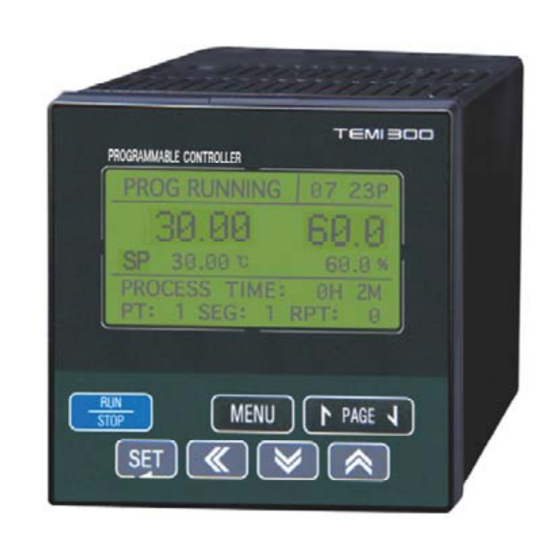
4.2 PROG Mode PROG Mode is controlling Temperature & Humidity with programmed data PTNO : Set pattern No.(Set with “SET” key) SEGNO : Start segment No. READY : Ready to running Start running by “RUN/STOP” key PROG running 1st screen PROG RUNNING : Prog running state PROCESS TIME : Running time RPT : Repeat pattern No. - Page 12 Symbol Parameter Range Display Unit Default Edit T.EU T.EU(0.0 ∼ 100.0%) T.EU T.SP TEMP SP Always (0.0%) H.EU When HUMI H.EU(0.0 ∼ 100.0%) H.EU H.SP HUMI SP (0.0%) OPER=ON 0 ∼ 10 PTNO PATTERN NUMBER Always O*note SEGNO SEGMENT NUMBER 0∼100(00) Always 00H00M ∼...
-
Page 13: Main Screen Operation & Setting
4.3 MAIN Screen Operation & Setting 4.3.1 FUNCTION MENU KEY FUNCTION SET KEY SUB SET setting MAIN MENU FUNCTION SUB SET SET KEY SUB SET1, SUB SET2 (PAGE UP/DOWN KEY) OPER MODE : FIX / PROG PWR MODE : State mode after power failure Can be recognized over 3 sec. - Page 14 Communication set FUNCTION MAIN MENU COMM SET SET KEY BPS : Speed (Bit per sec) PRTY : Parity S.BIT : Stop bit D.LEN : Data length AT TUNING set MAIN MENU FUNCTION AT TUNING SET KEY AT TUNING is available on “FIX RUN” state only Available on FIX RUN MODE only AUTO TUNING with SP on FIX MODE only then after auto tuning the value of tuning is saved on the correspond PID number...
- Page 15 Symbol Parameter Range Display Unit Default Edit PROG, FIX PROG OPER MODE OPERATION MODE Always STOP, COLD, HOT STOP PWR MODE POWER MODE Always OFF, ON KEY LOCK KEY LOCK Always OFF, ON BUZZER BUZZER Always OFF, ON FUZZY FUZZY Always 0 ∼...
-
Page 16: Program
4.3.2 PROGRAM MENU KEY MAIN PROGRAM SET KEY EDIT SEG set MAIN MENU PROGRAM EDIT SEG SET KEY Set the temperature, humidity, time, TS1, TS2 and TS3 for each segment 1 : TS1(Time Signal1) 2 : TS2(Time Signal2) 3 : TS3(Time Signal3) EDIT PT set MAIN MENU PROGRAM... - Page 17 WAIT SET set MAIN MENU PROGRAM WAIT SET SET KEY TEMP ZONE : The range of temperature for waiting zone HUMI ZONE : The range of humidity for waiting zone WAIT TIME : Time for wait WAIT USE : Use / Not use Clear all of the patterns &...
- Page 18 Symbol Parameter Range Display Unit Default Edit 0.00 ∼ 99.59 0.00 WAIT TIME WAIT TIME(HH.MM) Always ON, OFF WAIT USE WAIT USE Always OFF, ON PT A.CLR Always ALL PATTERNS DELETE OFF, ON SEG A.CLR Always ALL SEGMENTS DELETE ※ Wait The wait function holds off the transition of segment until deviation is cleared up.
-
Page 19: Reserve
4.3.3 RESERVE RESERVE set MENU KEY MAIN RESERVE SET KEY NOW : Display present year, month, date and time which is set on SET DATE area RUN DATE : Set reserved starting year, month, date and time SET DATE : Set present year, month, date and time RESERVE : Use/not use Symbol Parameter... -
Page 20: Graph
4.3.4 GRAPH GRAPH set MENU KEY MAIN GRAPH SET KEY Symbol Parameter Range Display Unit Default Edit Set PT on PATTERN NUMBER 1 ∼ 10 Always MAIN Set SEG on 1 ∼ 99 SEGMENT NUMBER Always T.EU(0.0 ∼ 100.0%) T.EU T.SP TEMP SP Always... -
Page 21: Setup Screen
4.4 SETUP 4.4.1 INPUT SETUP set. MENU KEY MAIN SETUP SET KEY SET KEY Illuminate No. Password with UP, DOWN, SHIFT KEY SET KEY INPUT SET KEY TYPE:Sensor type for temperature RND.HIGH(LOW):Range of using temperature RANGE:-90.0 -- 200.0 T.BIAS:Bias for temperature TYPE:Sensor type for humidity RND.HIGH(LOW):Range of using humidity RANGE:-10.0 -- 110.0... - Page 22 Symbol Parameter Range Display Unit Default Edit TEMP SENSOR -90.0 -- 200.0 TYPE Always HUMI SENSOR -10.0 -- 110.0 TEMP RANGE HIGH T.EU T.EU(100.0%) T.EU(0.0∼100.0%) RNG.HIGH Always H.EU H.EU(100.0%) HUMI RANGE HIGH RNG.LOW<RNG.HIGH H.EU(0.0∼100.0%) TEMP RANGE LOW T.EU T.EU(0.0%) RNG.LOW Always RNG.LOW<RNG.HIGH H.EU...
-
Page 23: Output
4.4.2 OUTPUT OUTPUT SET KEY KIND : Set type of temperature retransmission (PV, SP, MV) RNG.HIGH : Range of high RNG.LOW : Range of low PV : PV SP : SP MV : MV KIND : Set type of humidity retransmission (PV, SP, MV) RNG.HIGH : Range of high RNG.LOW : Range of low PV : PV... -
Page 24: On/Off
4.4.3 ON/OFF ON/OFF SET KEY ON/OFF mode for temperature HIGH.SP : Set low SP on ON/OFF HIGH.DIFF : Deviation value for high zone ON/OFF mode for temperature MIDDLE.SP : Set middle SP on ON/OFF ON/OFF mode for temperature LOW.SP : Set low SP on ON/OFF LOW.DIFF : Deviation value for low zone ON/OFF mode for temperature HIGH.SP : Set high SP on ON/OFF... - Page 25 1. T1∼T3, H1 (ON after set time, the set time adapted on first “ON” state at running) ① NPV < LSP(LOW.SP) Output : OFF ② NPV > HSP(HIGH.SP) Output : OFF ③ LSP ≤ NPV < MSP(MIDDLE.SP) NPV ≥ NSP-LD(LOW.DIFF) Output : ON NPV <...
-
Page 26: Inner Signal(Is)
4.4.4 Inner Signal(IS) INNER SET KEY KIND : Set type of humidity retransmission (PV, SP, MV) RNG.HIGH(LOW) : Range for IS BAND : Direct of IS band (IN.B/OUT.B) DELAY. TM : IS delay time IS1 connected with 1ST REF, 2ND REF output INNER SIGNAL : There are 1 ∼... -
Page 27: Alarm
4.4.5 ALARM ALARM SET KEY ITEM : Set item of alarm KIND : Set type of alarm POINT : Set alarm point HYS. : Set hysteresis for alarm DELAY.TM : Set the delay time for alarm output ALARM SIGNAL : There are 1 ∼ 4 pages of alarm Alarm is working on even STOP state NOTE Symbol... - Page 28 (Table 1 : Alarm Type) Output Direct Standby Alarm Type Display Data AH.F PV Upper-Limit AL.F PV Lower-Limit DH.F Deviation Upper-Limit DL.F Deviation Lower-Limit DH.R Deviation Upper-Limit DL.R Deviation Lower-Limit DO.F Deviation Upper & Lower-Limit DI.F Deviation Upper & Lower-Limit Range AH.R PV Upper-Limit AL.R...
-
Page 29: Do Config
4.4.6 DO CONFIG DO CONFIG SET KEY DO CONFIG set (1st page) Set the relay number (1~8) for IS1 6 and TS1 3 DO CONFIG set (2nd page) Set the relay number (1~8) for ALARM1 4, T.RUN and H.RUN DO CONFIG set (3rd page) Set the relay number (1~8) for T1 T4, and H1.RUN also set the delay time for each items The delay time effect only first ON time and next ON is not effect... - Page 30 DO CONFIG set (5th page) Set the relay number (1~8) for H.UP, H.SOK, and H.DN H.UP : Output until X% [X=TSP - set humidity] H.SOK : Output until X min [X=SOAK zone time - set time] H.DN : Output until X% [X=T.SP - set humidity] DO CONFIG set (6th page) DRAIN : Output on the zone that humidity is not used.
- Page 31 Symbol Parameter Range Display Unit Default Edit 0∼120(0:OUTPUT OFF) T.UP TEMP UP SIGNAL Always T.EUS T.EUS(0.0∼100.0%) T.EUS T.UP PARA TEMP UP PARA Always (0.0%) T.SOK TEMP SOAK SIGNAL 0∼120(0:OUTPUT OFF) Always 0∼999 MIN T.SOK PARA TEMP SOAK PARA Always 0∼120(0:OUTPUT OFF) T.DN Always TEMP DOWN SIGNAL...
-
Page 32: Bias
4.4.7 BIAS SET BIAS SET SET KEY Set bias for dry temperature P : Point (Boundary point) D : Bias value P=RH Actual Temperature P=P2 Temperature P=P1 after Bias P=RL (Figure 10 : Ex. Piece Bias Formula) Set bias for wet humidity P : Point (Boundary point) D : Bias value .30. - Page 33 Symbol Parameter Range Display Unit Default Edit TEMP REFERENCE T.EU T.EU DP.RL Always (0.0%) BIAS RL T.EU(0.0∼100.0%) TEMP REFERENCE T.EU T.EU DP.P1 Always (100.0%) BIAS POINT1 RL≤DP.RL<DP.P1 TEMP REFERENCE T.EU T.EU DP.P2 Always (100.0%) BIAS POINT2 <DP.P2<DP.RH≤RH TEMP REFERENCE T.EU DP.PH Always T.EU...
-
Page 34: Di Name
4.4.8 DI NAME DI NAME SET KEY DI1 : RUN/STOP Not changeable DI2, 3, 4 NAME : SET KEY UP, DOWN key TOG GROUP : PAGE UP, PAGE DOWN key when name is illuminate Symbol Parameter Range Display Unit Default Edit RUN/STOP RUN/STOP... -
Page 35: Password
4.4.9 PASSWORD PASSWORD SET KEY Set the new password SET KEY UP, DOWN, SHIFT key SET KEY PROG OPER : ON edit “OPER MODE” , not edit “OPER MODE” PROG OPER is not available on “RUN”. HUMI OPER : ON 2-LOOP (Temperature/Humidity) 1-LOOP (Temperature) Default password is 0(ZERO) -
Page 36: Pid Set
4.4.10 PID SET PID SET SET KEY TEMP.RP1, RP2 : Boundary value on temperature span for PID zone HUMI.RP : Boundary value on humidity span for PID zone When use TEMP & HUMI TEMP only H.RP T.RP2 T.RP1 DRY.H DRY.L (100.0) (0.0) (Figure 11 : PID Group) - Page 37 Symbol Parameter Range Display Unit Default Edit 0.1 ∼ 99.9 % 50.0% TEMP.RP1 TEMP REFERENCE1 Always T.EU T.EU T.EU TEMP.RP2 TEMP REFERENCE2 Always (0.0+1digt ~100.0-1digit) (100%/2) H.EU H.EU(0.0 ~100.0) H.EU HUMI.RP HUMI REFERENCE Always (100%/2) PROPORTIONAL 0.1 ∼ 999.9 Display BAND 0 ∼...
-
Page 38: Trouble Shooting
4.5 TROUBLE SHOOTING If the system, which this controller (NOVA series) adapted, has troubles (if you used DI2~DI4), the page appear also display WARN at the item state as picture You must solve the error before reusing the controller, otherwise you are reach error again. -
Page 39: Installation
5. Installation 5.1 Dimension & Panel Cutting Size (Unit : mm) 11.4 99.6 1mm~10mm (PANEL Thickness) .37. -
Page 40: Power Cable Specification
5.2 Power Cable Specification Applicable power source cable : Vinyl insulation cable KSC 3304 0.9~2.0 ㎟ 5.3 Terminal Specification Please use-tightening torque with insulating sleeve for M3.5 screws as shown in the following Figure: Φ3.0㎜ or more Note: When the screw is connected, its torque does not exceed 0.8 N·m. CAUTION ▶... -
Page 41: Terminal Arrangement And External Wiring
5.4 Terminal Arrangement and External Wiring RELAY RLY1 RLY2 RLY3 RLY4 Capacity: Capacity:250V AC 1A RS232 Less then 24VDC 50mA 30V AC 1A RTX+ OUT1(-) RTX- OUT2(-) COM(+) MAX:9600bps INPUT 1 AOUT1(+) AOUT1(-) AOUT2(+) AOUT2(-) INPUT 2 RET 4~20mA DC POWER RELAY RLY5... -
Page 42: Grounding And Power Cable Connection
5.5 Grounding and Power Cable Connection ■ Use a cable 2 ㎟ or more thick for grounding with class 3 grounding (grounding resistance a 100Ω or less) or higher. Do not extend the grounding cable over 20m. ■ Ground from the ground terminal with a one-point contact. Do not wire between ground terminals. -
Page 43: Analog Output Connection
4∼20mADC, 600 Ω max SHIELD RET+ Control Valve RET- TEMI300 Class 3 Ground ▶ Before starting receiver( or recorder, etc) install/uninstall wiring, be sure to turn off the TEMI 300 or else you will get an electrical shock. CAUTION .41. -
Page 44: External Contact Output Connection(Relay)
8 External Contact Output Connection (RELAY) RLY_NO TEMI300 Before starting analog input wiring, be sure to turn off the system otherwise you might get an electrical shock. CAUTION 5.9 External Contact Output Connection(OPEN COLLECTOR : DO) load TEMI300 Power Supply 24V DC 50mA or less 5.10 External Contact Input Connection (DI) ▶... -
Page 45: Use An Auxiliary Relay
5.11 Use an Auxiliary Relay ■ If you INDUCTANCE(L) load like as AUXILIARY RELAY or SOLENOIDE VALVE, it might make go to wrong or out of order relay, please make sure insert to parallel circuit with CR FILTER(AC) or DIODE(DC) by SURGE SUPPRESSOR of avoiding sparks. ■... -
Page 46: Wiring For Communication
6. Wiring for Communication TEMI300 communication terminal arrangement is as below 6.1 RS232 Interface Connection with TEMI 300 TEMI 300 Before starting analog input wiring, be sure to turn off the system otherwise you might get an electrical shock. CAUTION...
Need help?
Do you have a question about the TEMI 300 and is the answer not in the manual?
Questions and answers