Table of Contents
Advertisement
Advertisement
Table of Contents

Related Manuals for Samwon Tech TEMI1000 Series


Summary of Contents for Samwon Tech TEMI1000 Series
- Page 2 Copyright Copyrightⓒ 2014 Samwontech Co., Ltd This operation manual is a work protected by the copyright law. A part or entire of this manual shall not be copied, air sent, distributed, translated or changed into the form to be read by electronic media or machine without prior written consent of Samwontech Co., Ltd.
-
Page 3: Table Of Contents
This manual is used for TEMI1000 of operation method. Contents 1. Operation and setting 6. Setting graph display and save 1-1 Basic operation flow chart ‥‥‥‥‥‥‥‥‥‥‥‥‥‥‥‥‥ 4 6-1 Pattern graph display ‥‥‥‥‥‥‥‥‥‥‥‥‥‥‥‥‥‥‥ 41 1-2 Setting button operation ‥‥‥‥‥‥‥‥‥‥‥‥‥‥‥‥‥‥ 5 6-2 Presented value (PV) graph view ‥‥‥‥‥‥‥‥‥‥‥‥‥‥ 44 1-3 Parameter setting method ‥‥‥‥‥‥‥‥‥‥‥‥‥‥‥‥‥ 6 6-3 Presented value (PV) graph save setting ‥‥‥‥‥‥‥‥‥‥‥ 47 6-4 Memory save setting ‥‥‥‥‥‥‥‥‥‥‥‥‥‥‥‥‥‥‥... - Page 4 Cautions (Instructions) for safety Thank you for your choice of our Temperature and Humidity Programmable Controller(TEMI1000). This manual describes the method of operation of the product. Cautions in this instruction manual Symbol marks for safety ■ Please deliver for the end user to possess always and keep it in the place accessible at any time. ■ Use the product after full understanding of this operation manual. (A) It means the“Handle with ■ This operation manual does not warrant any other things because it is a description of the details for the function. care” or “Cautions”In case of ■ A part or whole of this manual shall not be edited or copied randomly. violation of this point, it may cause ■ The descriptions in this manual may be changed randomly without pre notice or warning. the death, severe injury or the ■ Even though this manual was made with elaboration, it will be appreciated if you inform to the purchasing point (Dealer shop and etc) extreme damage on the product. or sales team in our company in case of deficiency, mistake or omission in the contents. ■ Product: It is marked on the Cautions for the safety and modification (Change) of the product points to be acknowledged ■ Please use this product after full understanding on the safety cautions in this manual for the protection and safety for this product and certainly to protect the human...
-
Page 5: Operation And Setting
Part Operation and setting 1-1 Basic operation flow chart ‥‥‥‥‥‥‥‥‥‥‥‥‥‥‥‥‥‥‥‥‥‥‥‥ 4 1-2 Setting button operation ‥‥‥‥‥‥‥‥‥‥‥‥‥‥‥‥‥‥‥‥‥‥‥‥‥ 5 1-3 Setting button operation ‥‥‥‥‥‥‥‥‥‥‥‥‥‥‥‥‥‥‥‥‥‥‥‥‥ 6... -
Page 6: Basic Operation Flow Chart
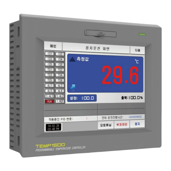
01. Operation and setting This product is programmable controller designed with dialogue style touch screen easy-to-use for the users. 1-1. Basic operation flow chart ● The logo screen and the initial screen are displayed sequentially when the electric power is switched “ON” after installation of the product and it converts to the program stationary screen. ● It takes about 20 seconds for screen loading ● When button is touched at the top of the program stationary screen, it converts to the main screen. ● Refer to [13. System initial setting] in [Installation manual] for change in the initial screen. Logo screen Initial screen Stationary operation still screen(TEMI1500) Main screen(TEMI1500) Stationary operation still screen(TEMI1300/1900 WIDE) Main screen(TEMI1300/1900 WIDE) -
Page 7: Setting Button Operation
1-2. Setting button operation Button type Button operation The “Set value” is touched in stationary operation/still screen and it is used for setting the set value wanted by the user. The “Pattern No.” is touched in program still screen and it is used for setting the pattern number wanted by the user. It is used for inputting the general numbers and name. It is used for selection for one out of many types. It is used for selection for one out of more than 2 parameter setting. (ON/OFF/Inactive state) It is used for selection of Y/N for the corresponding parameter. (ON/OFF/Inactive state) It is used for general screen conversion. It is used for increasing or decreasing of the page within the same screen. It is used for the page conversion by the decrease and increase in time axis on the same screen. -
Page 8: Parameter Setting Method
1-3. Parameter setting method ● When is selected in [1-2 Setting button operation], the input key of the setting value is shown as followings and the necessary data can be input. ● When the data out of the setting range is input, error message (“LIMIT ERROR”) is shown on the input data display window with the error sound (“Beep”). ▲ Input key for setting only the numbers Input key for setting the pattern experiment name and DI ▶ error name Refer to [11. DI function and operation setting] in [Operation manual] for DI error name input key. ▲ Input key for time signal setting ▲ Display when it is out of the setting range Touch key lock release ● Input OFF (Lock release state) for key lock because the set value is not input when “Key lock” is “ON.” ● Refer to [4. Operation motion setting] for details... - Page 9 (1) Method for effectiveness of setting button and setting value ● This product is designed as follows when the setting data input button is touched or to check the effectiveness of the input setting data by sound. ● “Beep” : When the basic setting button is touched or the setting data is input normally ● “Beep and beep” : When the input data by the setting data input key is out of the input range. ● Do not press with sharp thing (Pencil and etc) or excessive force on the input key for basic setting button or setting value. It may cause the mal operation of the device or damage on the touch panel. (2) Setting value input method ● Every input data used in this product is set by the set data input key, test name input key and time signal input key. ● The input key for set data is appeared when button is touched in [1-2 Setting button operation] and the value to be set can be input. ● Refer to [7-4 Time signal operation] for time signal input. ● Refer to [11. DI function and operation setting] in [Operation manual] for DI error name input key. ▶ Set the value of the input key features and descriptions ① It displays “Parameter.” ② It displays “Setting range.” It displays “setting display window.”...
- Page 10 Part Main screen ‥‥‥‥‥‥‥‥‥‥‥‥‥‥‥‥‥‥9...
-
Page 11: Main Screen
02. Main screen [Fig. 2-1] Main screen(TEMI1500) No. Instruction Description Operation ① Moving to the operation screen state screen Setting Moving to the setting screen for additional function ② operation motion and operation method Programmed Moving to the screen for setting current time, ③ operation setting programmed operation time. Moving to the screen to set Y/N for using graph ④ Graph & Saving display, graph record Moving to the program setting menu screen ⑤ Program setting Moving to the screen for setting the screen Setting screen brightness, Y/N for using buzzor sound, back light ⑥ display electricity saving, setting for background color and humidity display. - Page 12 [Fig. 2-2] Main screen(TEMI1300/1900 WIDE) ① It displays the current date/time. ② It displays the present temperature value (PV). ③ It displays the present humidity value (PV). Button to move the operation screen. ④ During operation, the button is displayed alternately in ● various colors. References ▶ PV on the left side of the screen is displayed on the left side of all parameters in the TEMI1300/1900(WIDE) Product...
-
Page 13: Operation State Screen Setting
Part Operation state screen setting 3-1 Stationary operation ‥‥‥‥‥‥‥‥‥‥‥‥‥‥‥‥‥‥‥‥‥‥‥‥‥‥‥ 13 3-2 Program operation ‥‥‥‥‥‥‥‥‥‥‥‥‥‥‥‥‥‥‥‥‥‥‥‥‥‥‥ 20 3-3 Auto tuning and tuning point ‥‥‥‥‥‥‥‥‥‥‥‥‥‥‥‥‥‥‥‥‥‥‥ 29... - Page 14 Operation state screen setting Flow chart [Fig. 3-1] Stationary operation still screen 1 [Fig. 3-5] Stationary operation still screen 1 [Fig. 3-9] Stationary operation still screen 2 [Fig. 3-10] Stationary operation still screen 3 Part 03...
-
Page 15: Stationary Operation
03. Operation state screen setting 3-1. Stationary operation (1) Stationary operation still screen 1 ● When the operation state screen is selected in [Fig. 2-1 Main Screen], it is converted to “Stationary operation still screen 1.” ● Select the operation method with “Stationary” in [4. Operation motion setting] ● When at the right bottom of [Fig. 3-1] Stationary operation still screen 1 is touched by, it converts to [Fig. 3-5] Stationary operation still screen 1. [Fig. 3-1] Stationary operation still screen 1 [Fig. 3-2] Stationary operation still screen 1 (User Key) - Page 16 [Fig. 3-4] Screen of Input for humidity setting about operation [Fig. 3-3] Screen of Input for temperature setting about operation temperature Parameter Setting range Unit Initial value References Temp setting data(SP) T.EU(0.00 ~ 100.00%) T.EU T.EU(0.00%) ▶ The input for set value for temperature is activated when Humi setting data(SP) H.EU(0.0 ~ 100.0%) H.EU H.EU(0.0%) button is touched [Fig. 3-3 creen of Input ※ T.EU : Range of input data for temperature sensor for temperature setting about operation temperature] ※ H.EU : Range of input data for humidity sensor ▶ The input for set value for humidity is activated when ※ Refer to [Engineering units] button is touched. [Fig. 3-4 Screen of Input for humidity setting about operation] ▶ When the input of set data of temperature and humidity are completed, operate the stationary operation by selecting .
- Page 17 (2) Stationary operation #1 operation screen ● When the “Setting data” is touched even in operation, the input key setting for operation is activated. ● It is a screen for Measured data and Set data. [Fig. 3-5] Stationary operation operation screen 1 ① It displays the temperature setting data (SP) to be controlled. ② It displays the present temperature value (PV). It displays the present humidity value (PV). ③ It displays the humidity setting data (SP) to be controlled. ④ It displays the current date/time and LCD backlight is off when it is touched. ⑤ Red LED lamp at the right top is ON when the backlight is OFF in still state. ● Moving to [Fig. 2-1 Main screen] ⑥ It displays the key pad to input the password when main button restriction is set. ● Refer to [Fig. 4-2 Screen in restriction setting of main button] ● ⑦ Moving from current screen to next screen Execution or releasing the auto tuning with temperature set value (SP). ⑧ Y/N of the tuning button display is set in [8. PID group] in [Operation manual] ● Execution or releasing the auto tuning with humidity set value (SP). ⑨...
- Page 18 (3) Stationary operation screen 1 (TEMI1300/1900 WIDE) [Fig. 3-6] Stationary operation still screen 1 [Fig. 3-7] Stationary operation operation screen 1...
- Page 19 (4) Stationary operation #2 operation screen ● It is a screen to display the display lamps for measuring data, setting data and output volume. [Fig. 3-9] Stationary operation #2 operation screen [Fig. 3-8] Stationary operation #1 expanded screen ③ It displays the control output volume (MV). The “ON” state is It displays the control output volume (MV) in humidity. displayed in red and “OFF” state is displayed in dark grey. It displays the currently applied PID group number. ① ④ Setting the state lamp in [12. System initial setting] in [Installation manual] The applied PID group can be checked in [8. PID group] in [Installation manual] ● ● ⑤ Setting up to 24 for lamp in [12. System initial setting] It displays the total process time of stationary operation. ● ② It displays the control output volume (MV) in temperature.
- Page 20 (5) Stationary operation #3 operation screen ● The above screen is to display the measuring date, setting data of Temperature and Humidity. The direction of graph is horizontal. ● ( ) check box sets Y/N for data display. ● Possible to save recording values into the internal memory using this button ● The saved data into the internal memory are preserved when the electric power is "ON/OFF" ● Refer to [6-2 Present value (PV) graph view] [Fig. 3-10] Stationary operation #3 operation screen [Fig. 3-11] Stationary operation #3 operation screen (User Key) It displays the measuring data, setting data of currently operated It is a button to save the measuring data, setting data of currently ① ③ Temperature and Humidity. recorded Temperature and Humidity into the Internal memory. It displays the capacity of internal memory. ② About 90 days of saving is available when the sampling time is set in 1 second. ●...
- Page 21 (6) Termination screen for operation of stationary time setting ● The stationary operation is terminated while it shows the message, “The time setting operation is terminated.” when the operation is terminated by the elapse of setting time in [4. Operation motion setting] ● The message is not appeared on the screen when it is forcibly terminated by pressing “Stop” button during operation. ● The message is disappeared by touching the corresponding part when the operation termination message is display in case of operation termination. (It is same with the program operation termination.) [Fig. 3-12] Termination screen for operation of stationary time setting...
-
Page 22: Program Operation
3-2. Program operation (1) Program operation still screen 1 ● It converts to “Program operation still screen 1” when the operation state screen is selected in [Fig. 2-1 Main screen]. ● Select the operation method with “Pattern” in [4. Operation motion setting]. ● Refer to [7-1 Program pattern setting] for pattern setting method. ● It converts to [Fig. 3-13 Program operation #1 operation screen] when is touched by on the right bottom in [Fig. 3-16 Program operation #1 still screen] [Fig. 3-13] Program operation #1 still screen [Fig. 3-14] Program operation #1 still screen (User Key) - Page 23 Parameter Setting range Unit Initial value Pattern number 1~120 Cautions in operation ● It is not operated when the program is not input into the pattern number on the screen. ● Refer to [7-1 Program pattern setting] [Fig. 3-15] Screen for pattern number setting input key to be operated References ▶ When the button is touched by for inputting the pattern number setting to be operated, it is activated as shown in [Fig. 3-15] Screen for pattern number setting input key to be operated. ▶ Execute the program by selecting button when the input for the pattern number setting to be operated is completed.
- Page 24 (2) Program operation #1 operation screen ● The pattern number cannot be set during operation. ● It is a screen for Measured data and Set data. [Fig. 3-16] Program operation operation screen 1 ① It displays the temperature setting data (SP) to be controlled. ② It displays the present temperature value (PV). ③ It displays the present humidity value (PV). It displays the humidity setting data (SP) to be controlled. ④ It displays the current date/time and LCD backlight is off when it is touched. ⑤ Red LED lamp at the right top is ON when the backlight is OFF in still state. ● Moving to [Fig. 2-1 Main screen] ⑥ It displays the key pad to input the password when main button restriction is set. ● Refer to [Fig. 4-2 Screen in restriction setting of main button] ● ⑦ Moving from current screen to next screen Maintaining (Hold On) or Release (Hold Off) the currently operating ⑧ temperature and humidity set value. ⑨ Terminating the currently processing segment and forced moving to the next segment. Execution or releasing the auto tuning with temperature set value (SP).
- Page 25 (3) Program operation screen 1 (TEMI1300/1900 WIDE) [Fig. 3-17] Program operation still screen 1 [Fig. 3-18] Program operation operation screen 1...
- Page 26 (4) Program operation #2 operation screen ● It is a screen to display the display lamps for measuring data, setting data and output volume. [Fig. 3-20] Program operation #2 operation screen [Fig. 3-19] Program operation #1 expanded screen It displays the control output volume (MV). The “ON” state is It displays the partial repetition state. ⑥ displayed in red and “OFF” state is displayed in dark grey. The figure in the front of shows the frequency ● ① Setting the state lamp in [12. System initial setting] in [Installation manual] of repetition and the figure at the end shows the set repetition frequency. ● Setting up to 24 for lamp in [12. System initial setting] It displays the currently applied PID ground number. ● ⑦ ② It displays the control output volume (MV) in temperature. The applied PID group can be checked in [8. PID group] in [Installation manual]. ● ③ It displays the control output volume (MV) in humidity. It displays the segment process time and setting time of currently processing segment. ④ It displays the currently operated program pattern number and segment number. The time in the front of shows the ●...
- Page 27 (5) Program operation #3 operation screen ● The above screen is to display the measuring date, setting data of Temperature and Humidity. The direction of graph is horizontal. ● ( ) check box sets Y/N for data display. ● Possible to save recording values into the internal memory using this button ● The saved data into the internal memory are preserved when the electric power is "ON/OFF" ● Refer to [6-2 Present value (PV) graph view] [Fig. 3-21] Program operation #3 operation screen [Fig. 3-22] Program operation #3 operation screen (User Key) It displays the measuring data, setting data of currently operated It is a button to save the measuring data, setting data of currently ① ③ Temperature and Humidity. recorded Temperature and Humidity into the Internal memory. It displays the capacity of internal memory. ② About 90 days of saving is available when the sampling time is set in 1 second. ●...
- Page 28 (6) Termination screen for operation of program ● The program operation is terminated while it shows the message, “The program operation is terminated.” when the operation for segment setting range saved into the pattern is terminated. ● The message is not appeared on the screen when it is forcibly terminated by pressing “Stop” button during operation. ● The message is disappeared by touching the corresponding part when the operation termination message is display in case of operation termination. (It is same with the stationary operation termination.) [Fig. 3-23] Termination screen for operation of program...
- Page 29 (7) Other operation screen ● It is a screen to display warning in operation screen. [Fig. 3-24] Screen for sending the saved PV file [Fig. 3-25] Screen for warning of shortage of memory capacity References References ▶ It is a sending screen for saved PV file in internal memory to PC ▶ It is a screen when internal memory capacity is up to 60.8 megabytes. It takes about 23 second to sending 0.1M byte.
- Page 30 [Fig. 3-26] Warning screen for no extra space in memory [Fig. 3-27] Warning screen for lack of saved file number References ▶ Screen for no extra space in intenal memory. References ▶ [Fig. 3-27] is a screen when the number of saved files is over 240 in internal memory. ▶ [Fig. 3-28] is a screen when the number of saved files is fulled up to 256. [Fig. 3-28] warning screen for full of saved file number...
-
Page 31: Auto Tuning And Tuning Point
3-3. Auto tuning and tuning point ● The segment is held during program operation and the segment is processed when the auto tuning is terminated. ● Auto tuning is a function to set the optimal PID integer automatically by measuring and calculating the object of control with controller. ● The controller generates the ON/OFF control output during “2.5 periods” during auto tuning and it calculates the P, I, D data automatically based on the period and oscillation magnitude using the limit cycle to the object to be controlled. ● The Auto-Tuning is available in program.stationary operation. The PID data calculated from the set value located PID group is saved automatically through Auto-Tuning from the currently set value. Under tuning PD control Measuring data Cautions in operation (PV) ● Any change in set value (SP) in auto tuning does not change the tuning 50.2℃ point. And the tuning is started with changed set value (SP) for target SP = 50.0℃ set value (TSP) after auto tuning termination. ● The auto tuning is stopped in case of “Sensor short” in input during 49.8℃ auto tuning. At this time, the PID data is kept with the previous set value. ● When auto tuning is processed beyond 27 hours, the auto tuning is stopped. ● The PID set value can be changed during auto tuning, but the obtained PID data from calculating in auto tuning termination is reset with the obtained PID data. Control output ● The PID set value is maintained with previous set value when the data (MV) auto tuning is forcibly terminated. ● For better Auto-Tuning results, need to wait until stabilization by set value(temperature), then Autotuning the temperature first. Auto tuning operation And after Autotuning the humidity, will get better P, I and D value(data) References ▶ An example of auto tuning depending on the set value. -
Page 32: Operation Motion Setting
Part Operation motion setting 4-1 Operation method setting ‥‥‥‥‥‥‥‥‥‥‥‥‥‥‥‥‥‥‥‥‥‥‥‥ 31 4-2 Fuzzy operation ‥‥‥‥‥‥‥‥‥‥‥‥‥‥‥‥‥‥‥‥‥‥‥‥‥‥‥‥ 33 4-3 Setting value change rate (SLOPE) operation ‥‥‥‥‥‥‥‥‥‥‥‥‥‥‥ 34... -
Page 33: Operation Method Setting
04. Operation motion setting It is a screen for general additional functions and additional setting in stationary operation. 4-1. Operation method setting ● It converts to the “Setting screen for operation related motion” when the operation motion setting is selected in [Fig. 2-1 Main screen] Setting with selection either of pattern or stationary operation [Fig. 4-1] Setting screen for operation related motion for operation mode.(It cannot be changed during operation.) ① Pattern : Setting in program operation ● Stationary : Setting in stationary operation ● Setting the recovery motion in black out Stop : A motion to return to the operation stop state after ● power on from the black out. ② Re-start : An operation from the beginning after power on from ● the black out. Continue : A motion to return to the previous operation state ● after power on from the black out. In case that the external disturbances occure, stabilized the control. No operation : The indicated value is stabilized depending on time ● ③ when the overshoot is made. - Page 34 The key pad to input the password is displayed when the main button is Return motion Stationary Program operation ⑥ touched by in the operation screen for setting the main button restriction setting. in black out operation Refer to [Fig. 4-2 Screen for main button restriction setting] Stop Program stop Stop ● The parameter setting is impossible when button is touched by Re-start Operation from the first segment Operation ⑦ Screen rolling and key block releasing is possible. Operation from the segment ● Continue Operation before black out Parameter Setting range Unit Initial value Operation method Pattern, stationary Pattern Returning motion in black out Stop, re-start, continue Stop Fuzzy function No operation, Operation No operation...
-
Page 35: Fuzzy Operation
[Fig. 4-2] Main button restriction setting screen 4-2. Fuzzy operation ● The overshoot may be taken place in case of severe change in operation or frequent changes in present value (SP). More effective control can be made when the fussy function is operated at this time. ● Internal operation sequence of fuzzy function: It controls the overshoot by calculating the control output value (MV) with sub target value (Super SP) instead of present value (PV) from the overshoot control start time. Now present value(NPV) Now present value(NPV) SUPER SP Set value Set value (SP) (SP) : Sub set value (Super SP) Starting of internal calculation SUPER SP Overshoot control start : Sub set value (Super SP) Time Time Start of application SUPER SP Overshoot control start... -
Page 36: Setting Value Change Rate (Slope) Operation
4-3. Setting value change rate (SLOPE) operation ● The set value is changed by fixed changing rate from the now present value (PV) to set value when the set value is changed. References 70.0℃ ▶ Operation method: Stationary operation ▶ Temperature change rate: 20.0℃/Min 40.0℃ ▶ Change [Changed SP(TSP) - PV at the SP changing point] with slope of 20.0℃ 30.0℃ per minute: (70.0-30.0)℃ = Change 40.0℃ with the slope of 20℃ ▶ Increase the current set value (SP) from 30.0℃ to 70.0℃ with uniform increasing rate for 2 minutes. 2minutes. SP change Change rate (Slope) operation... - Page 37 Part Appointed operation setting ‥‥ 36...
-
Page 38: Appointed Operation Setting
05. Appointed operation setting ● It converts to [Fig. 5-1 Time setting screen] when the appointed operation setting button is touched by in [Fig. 2-1 Main screen]. ● It is a screen to set the current time and appointed operation time. [Fig. 5-1] Time setting screen It sets the year, month, day and hour. ① The current time is not changeable during recording the measured ● data and operating. ② It sets the year, month, day and hour for appointed operation. The operation is possible in the set appointed time when is touched by. ③ The appointed time is displayed on the operation screen as shown ● in [Fig. 5-2 Operation appointed setting screen] when is touched by. - Page 39 [Fig. 5-2] Operation appointed setting screen [Fig. 5-3] Operation appointed setting screen (Stationary operation) (Program operation)
- Page 40 Parameter Setting range Unit Initial value Year 2000~2009 Month 1~12 1~31 Current time AM/PM AM, PM Hour 1~12 Minute 0~59 Year 2000~2009 2014 Month 1~12 Appointed operation 1~31 time AM/PM AM, PM Hour 1~12 Minute 0~59 Appointment Click for appointment. ※ AM12:00: Night 00:00/PM12:00: PM 12:00...
-
Page 41: Setting Graph Display And Save
Part Setting graph display and save 6-1 Pattern graph display ‥‥‥‥‥‥‥‥‥‥‥‥‥‥‥‥‥‥‥‥‥‥‥‥‥‥ 41 6-2 Presented value (PV) graph view ‥ ‥‥‥‥‥‥‥‥‥‥‥‥‥‥‥‥‥‥‥‥ 44 6-3 Presented value (PV) graph save setting ‥‥‥‥‥‥‥‥‥‥‥‥‥‥‥‥‥ 47 6-4 Memory save setting ‥‥‥‥‥‥‥‥‥‥‥‥‥‥‥‥‥‥‥‥‥‥‥‥‥‥ 48... - Page 42 Setting graph display and save Flow chart [Fig. 6-9] Graph & Saving screen 3 [Fig. 6-2] Graph & Saving screen 1 [Fig. 6-5 Graph & Saving screen 2 (Pattern graph display) (Graph display selection) [Fig. 6-10] Graph&Save setting screen 4 Part 06...
-
Page 43: Pattern Graph Display
06. Setting graph display and save 6-1. Pattern graph display ● It convert to the [Fig. 6-2 Graph & save #1 screen ], when the[Graph & Save] is selected in [Fig. 2-1 Main screen]. ● This screen displays the temperature and humidity operation pattern and progress time in program operation. ● It is a screen to display the input pattern in [Fig. 7-2 Pattern editing screen]. ● Can change the status of Temperature•Humidity Check, and , even in the graph screen. [Fig. 6-1] Graph & Save screen 1 (Program operation) [Fig. 6-2] Graph & Save screen 1 (graph thinkness) - Page 44 The temperature (Red) is disappeared on the graph screen when the checked [Fig. 6-3] Graph & Save screen 1 (Program operation) ① button is touched in the currently operating screen and temperature (Red) is displayed in the graph screen when button is touched again. , buttons are used even in during operation(RUN) . ● The humidity (Blue) is disappeared on the graph screen when the checked button is touched in the currently operating screen and humidity (Blue) is ② displayed in the graph screen when button is touched again. , buttons are used even in during operation(RUN) . ● Setting the pattern No. to be displayed Display the input key to set the pattern No. when ● ③ is touched. Refer to [Fig. 6-4 Pattern No. input screen] ● Setting the time on graph X axis Display of the input key to set the time on X axis when ● ④ is touched. The time on X axis can be changed during operation ① ● Display the current temperature during operation ⑤ Moving from current screen to next screen ② Display the current humidity during operation Change into the Previous/Next stage on the time axis when ③...
- Page 45 [Fig. 6-4] Pattern No. input screen References ▶ It is a screen to input the pattern No. to be displayed in graph. ▶ The pattern No. can be input even during operation. Parameter Setting range Unit Initial value Pattern No. 1 ~ 120 30 minutes, 1 hour, 3 hours, 6 hours, Display time 30 minutes 12 hours, 24 hours...
-
Page 46: Presented Value (Pv) Graph View
6-2. Presented value (PV) graph view ● It is a screen to display the data recorded in [3-1(5) Stationary operation 3 operation screen] and [3-2(5) Program operation 3 operation screen]. ● The function of , is not operated in case of 1 page for recorded data. ● The searching scroll bar is not displayed in case of smaller recorded data. ● The date and time saved into the memory are displayed out the screen. [Reference 1] [Fig. 6-5] Graph&Save setting screen 2 (Graph display is selected) Purple at base line temperature (Set Data, Indicated Data) and humidity (Set Data, Indicated Data) is displayed. ① When the checked is touched, it is disappeared on the graph ● screen and when is touched, it is displayed on the graph screen. Refer to [Fig. 6-5 and Fig. 6-6 Graph & Save setting screen 2] ● ② Display to update the graph screen immediately which is being saved. ③ Moving from current screen to next screen Base line to disply the data checkpoint ④ Using the touch screen and No.8 Button to move to the point where ● we want. ⑤ [Reference1] The time axis is expanded or reduced. ⑥... - Page 47 References ▶ It is a screen for no selection from the temperature (Set Data, Indicated Data) and humidity (Set Data, Indicated Data) ▶ It is a screen to display the saved file into the internal memory. ▶ Refer to [3-1(5) Stationary operation 3 operation screen] and [3-2(5) Program operation 3 operation screen] for saving into internal memory. [Fig. 6-6] Graph&Save setting screen 2 (Graph display is not selected)
- Page 48 [Fig. 6-7] Graph&Save setting screen 2 (Saved folder is displayed) [Fig. 6-8] Graph&Save setting screen 2 (Saved file is displayed) Copy the recorded PV files into the internal memory to SD card. ① The transmission is impossible when there is not SD card option or ● during saving the PV graph in operation screen. When is touched, the files saved into the internal memory is displayed. ② The currently opened folder or file is display in red. ● Move to the start and end in case of data searching ③ stored in the internal memory Move to the up and down in case of data searching ④ stored in the internal memory ⑤ Close the PV file ⑥ Move to the folder...
-
Page 49: Presented Value (Pv) Graph Save Setting
6-3. Presented value (PV) graph saving setting ● This screen is to set the display range and sampling time which are necessary for graph recording in [3-1(5) Stationary operation 3 operation screen] and [3-2(5) Program operation 3 operation screen]. [Fig. 6-9] Graph&Save setting screen 3 Setting the PV graph saving period It is not changeable during PV graph saving ● ① Saving about 90 days is possible when sampling time is set in ● 1 minute in saving into internal memory. Setting Y/N for saving the data into the internal memory. Auto: Saving the data in synchronized with Operation/Stop automatically ● Manual: Saving the data by the saving key in the Operation ● ② screen 3 manually The saved data into the internal meemory are preserved when ● the electric power is "ON/OFF" ③ Setting the display range of Temperature graph ④ Setting the display range of Humidity graph Parameter Setting range Unit Initial value Recording cycle 1Sec, 2Sec, 5Sec, 10Sec, 20Sec, 30Sec, 1Min... -
Page 50: Memory Save Setting
6-4. Memory save setting ● It is a screen to set the transmitting of pattern and parameter to SD card. ● It is a screen displayed in SD card option only. [Fig. 6-10] Graph&Save setting screen 4 Setting the items and direction of transmitting in SD card and TEMI1000 PTN : Download or upload the set pattern in ● [7-1 Program pattern setting] PARA : Download or upload the set parameter ● ALL : Download or upload the pattern and parameter ● ① Download : Transmitting the selected transmitting items out of ● the internal data in TEMI1000 to SD card Upload : Transmitting the selected transmitting items out of the ● saved data in TEMI1000 to SD card It displays the current capacity of SD card ② It displays when the SD card is inserted only ● When the data is not in recording to SD card, is activated and ③ download and upload are possible when is touched by. Parameter Setting range Unit Initial value Transmitting item Pattern, PARA, ALL Pattern... -
Page 51: Program Setting
Part Program setting 7-1 Program pattern setting ‥‥‥‥‥‥‥‥‥‥‥‥‥‥‥‥‥‥‥‥‥‥‥‥‥ 52 7-2 Pattern repetition setting ‥‥‥‥‥‥‥‥‥‥‥‥‥‥‥‥‥‥‥‥‥‥‥‥‥ 57 7-3 File editing ‥‥‥‥‥‥‥‥‥‥‥‥‥‥‥‥‥‥‥‥‥‥‥‥‥‥‥‥‥‥‥ 58 7-4 Time signal operation ‥‥‥‥‥‥‥‥‥‥‥‥‥‥‥‥‥‥‥‥‥‥‥‥‥‥ 61 7-5 Standby operation ‥‥‥‥‥‥‥‥‥‥‥‥‥‥‥‥‥‥‥‥‥‥‥‥‥‥‥ 64 7-6 Experiment name setting ‥‥‥‥‥‥‥‥‥‥‥‥‥‥‥‥‥‥‥‥‥‥‥‥ 66... - Page 52 Program setting [Fig. 7-2] Pattern editing screen [Fig. 7-3] Pattern and segment repetition [Fig. 7-4] File editing screen setting screen [Fig. 7-7] Time signal setting #1 [Fig. 7-10] Standby operation setting screen [Fig. 7-11] Experiment name setting screen Part 07...
- Page 53 07. Program setting ● It converts to [Fig. 7-1 Program setting screen] when the program setting button is touched by in [Fig. 2-1 Main screen]. ● It is a screen group to set the parameters related to the program operation. [Fig. 7-1] Program setting screen ① Moving to the pattern editing screen ② Moving to the screen for repetitive setting of pattern and segment ③ Moving to the screen for setting pattern copy and deletion ④ Moving to the screen for time signal setting ⑤ Moving to the screen for setting the standby screen ⑥ Moving to the screen for experiment name...
-
Page 54: Program Pattern Setting
7-1. Program pattern setting ● It is a screen to set the segment depending on the pattern number. ● Refer to [7-4 Time signal operation] for time signal setting. ● Please refer to the [7-5 Standby operation] to find things about the standby operation. ① Input the pattern number for segment setting [Fig. 7-2] Pattern editing screen Setting the start condition for program operation. NOW PV : It starts from the present PV for present set value SP in ● starting of program operation and progressed to the set time(TM1) for currently set value(SP1) in segment(SEG1) TEMP SSP : In case of starting the program operation, the present ● set value (SP) is started from temperature SSP and progresses to the set time (TM1) for currently set value 1 (SP1) in segment 1 (SEG1). ② HUMI SSP : It starts from the set SSP for present set value (SP) in ● starting of program operation and progressed to the set time (TM1) for currently set value 1 (SP1) in segment 1 (SEG1). ③ It sets the temperature set value of segment to be operated. ④ It sets the humidity set value of segment to be operated. ⑤ Setting the time of segment to be operated. It sets the time signal of the segment to be operated. 4 time signals can be set for each segment and each time signal ● ⑥ is set by selection from 18 types of time signal. Refer to [7-4 Time signal operation] ●... - Page 55 Selection of Y/N for using the Standby of Segment to operate. ⑦ Refer to [7-5 Standby operation] ● When one of the buttons (Segment 01~99) is touched by for segment insertion, the selected button (Segment 01~99) ⑧ and button are activated and the selected segment can be inserted when is touched by When one of the buttons (Segment 01~99) is touched by for segment deletion, the selected button (Segment 01~99) ⑨ and button are activated and the selected segment can be inserted when is touched by ⑩ Moving to left/right on the screen by 5 segment units. ⑪ Moving to [Fig. 7-1 Program setting screen] when is touched by...
- Page 56 ▲ The input key to set the pattern number is displayed ▲ It is a screen set with “TEMP SSP” for starting condition. when the “Pattern number” button is touched by. ▶ When the “Starting condition” button is touched by, ▲ It is a screen set with “HUMI SSP” for starting condition. the input key to set the starting condition is displayed...
- Page 57 ▲ , buttons are activated when ▲ The input key to set the set value is displayed when button is activated. (HUMI) button is touched by. ▲ The input key to set the set value is displayed when ▲ The input key to set the segment time is displayed when (TEMP) button is touched by. (Time) button is touched by.
- Page 58 References ▶ Input by pressing for time signal and SEG alarm input. ▶ Select to escape from input screen. ▶ The wanted time signal group can be input by pressing TS1~TS4 for the set value in [7-4 Time signal operation]. ▲ The input key to set the time signal is displayed when (Time signal) button is touched by. Parameter Setting range Unit Initial value Pattern number 1~120 Starting condition NOW PV, TEMP SSP, HUMI SSP NOW PV Segment #n TEMP SP T.EU(0.00~100.00%) T.EU T.EU(0.00%) Segment #n HUMI SP H.EU(0.0~100.0%) H.EU H.EU(0.0%) Segment #n Time -00.00.01(OFF) ~ 999.59.59(Hour, Min, Sec) -00.00.01 Segment #n Time signal 1 ~ 4 0 ~ 17 Segment #n Wait use No use, Use No use ※ #n : 1 ~ 99...
-
Page 59: Pattern Repetition Setting
7-2. Pattern repetition setting ① It sets the pattern number to perform the repetitive operation. ● It is a screen to set the function for entire or partial repetition of set pattern. ② It sets the repetition operation frequency of the set pattern. ● The operation method in pattern operation termination can be set. It sets the pattern number for repetitive operation in termination of ③ set pattern operation. [Fig. 7-3] Pattern and segment repetition Setting screen It sets the segment to start the partial repetitive operation out of ④ the set patterns. It sets the segment to terminate the partial repetitive operation out of ⑤ the set patterns. It sets the repetition frequency of the partial repetitive operation out of ⑥ the set patterns. It displays the experiment name of the set pattern. ⑦ The change of the experiment name can be changed in [7-6 Experiment name setting] ● The change is impossible as it is only for reading. ● It decides the next operation when the set pattern operation is finished. Operation stop : The pattern termination signal is generated and the ● ⑧ operation state is in program stop. -
Page 60: File Editing
7-3. File editing ● It is a screen to copy or delete the input segment values in [Fig. 6-1 Program pattern setting]. ● The pattern number in operation cannot be deleted. ● The deleted pattern cannot be recovere. [Fig. 7-4] File editing screen ① It sets the original pattern number to be copied. It sets the first and last pattern number to be copied. ② The first pattern is copied only when the last pattern is “0.” ● It deletes the first and last pattern number to be copied. ③ The first pattern is deleted only when the last pattern is “0.”. ● It displays the total patterns set in [Fig. 7-1 Program pattern setting]. ④ The change is impossible as it is only for reading. ● It displays the total segments set in [Fig. 7-1 Program pattern setting]. ⑤ The change is impossible as it is only for reading. ● ⑥ It copies the set pattern ① to the set pattern ②. ⑦ It initializes the set value of the pattern set in ③. ⑧ It initializes the set value of every pattern. - Page 61 [Fig. 7-5] File editing screen #1 [Fig. 7-6] File editing screen #2 References References ▶ The message : “It is a mistake of parameter setting.” appeares at ▶ The message : “There is no saved contents on the selected the bottom of screen for copying or deleting by wrong input of pattern.” Appears at the bottom of screen for copying or deleting pattern number. without saved data in the pattern No.
- Page 62 Parameter Setting range Unit Initial value Pattern number 1~120 Start pattern 0~120 Copy End pattern 0~120 Copy No use, Use No use start pattern 0~120 Selective deletion end pattern 0~120 All deletion No use, Use No use Message display Explanation “There is no saved information in the selected pattern.” It is displayed in case of copy when there is nothing saved in pattern number. “The copy is completed in the selected pattern.” It is displayed in completion of selected pattern copy. “The deletion is completed in the selected pattern.” It is displayed in completion of selected pattern deletion. “The copy is completed in every pattern.” It is displayed in completion of every pattern deletion. “The pattern to be copies is being used.” It is displayed in use of pattern.
-
Page 63: Time Signal Operation
7-4. Time signal operation ● The time signal operation is classified into ON/OFF operation, time setting operation and the set time signal is used for setting the time signal No. in segment setting in [7-1 Program pattern setting] (1) Time signal ON/OFF operation [Fig. 7-7] Time signal setting #1 The time signal is OFF during corresponding segment operation ① when “0” is selected. The change is impossible as it is only for reading. ● The time signal is ON during corresponding segment operation ② when “1” is selected. The change is impossible as it is only for reading. ● ③ Moving the screen up/down by 6 time signal units. - Page 64 (2) Time signal time setting operation ● The time signal 2~17 (TS2~17) operate depending on delay time and operation time. [Fig. 7-9] Time signal setting #3 [Fig. 7-8] Time signal setting #2 Parameter Setting range Unit Initial value The time signal is “ON” after setting time is elapsed in delay time from Delay time 000.00.00(OFF)~999.59.59 (Hour, Min, Sec) 000.00.00 the corresponding segment starting point. ① Operation time 000.00.00(OFF)~999.59.59 (Hour, Min, Sec) 000.00.00 However, the time signal is not operated when the corresponding ● segment time is bigger than delay time. The time signal is “ON” by the delay time in corresponding segment is “ON” only for set time in operation time. . ② However, the time signal is “ON” for the corresponding segment operation ● when the (delay time + operation time) is bigger than corresponding segment time and it is not operated in the next segment.
- Page 65 (3) Example of operation in time signal input Setting Time signal operation Operation time Time signal 1. Delay time = 000.00.00 Segment N time Segment (n-1)segment time n segment time (n+1)segment time ≥ Delay time + Operation time Operation time Delay time Time signal 2. Delay time ≠ 000.00.00 Segment (n-1)segment time n segment time (n+1)segment time Operation time Segment N time< Time signal 3. Delay time = 000.00.00 Delay time + Operation time Segment (n-1)segment time n segment time (n+1)segment time ☞ It does not Operation time make influence...
-
Page 66: Standby Operation
7-5. Standby operation ● It is a screen to set the temperature&humidity Stand-by Range and Stand-by Time during Program operation. ● The set standby operation here is applied to [Fig. 7-1 Program pattern setting]. ● Definition of standby operation - Coditions for Stand-by Operation Entry (“OR” condition) : In case of no entry of either of temperature or humidity into the set range for standby operation within the set segment time - Conditions for Stand-by Operation Release (“AND” condition) : In case of entry of temperature and humidity into the set range for standby operation - The standby time has indefinite value when the standby time is not set (Initial value). [Fig. 7-10] Standby operation setting screen ① It sets Y/N of standby operation. ② It sets the temperature range to be applied for standby operation. ③ It sets the humidity range to be applied for standby operation. It sets the standby time to be applied when the indicated data for temperature or humidity does not enter into the standby operation ④ range (TEMP PV or HUMI PV). It standbys indefinitely for entry to the standby operation range when ● the standby operation time is set in “00.00.” It decides either of “Entire” and “Maintain SEG” for standby operation method. Entire : The standby operation is applied to the set entire segment in ● ⑤ [7-1 Program pattern setting] Maintain SEG : The standby operation is applied only to the set ● maintain range segment in [7-1 Program pattern setting]... - Page 67 Parameter Setting range Unit Initial value Standby operation setting No use, Use No use TEMP standby operation range T.EUS(0.00~100.00%) T.EUS T.EUS(0.00%) HUMI standby operation range H.EUS(0.0~100.0%) H.EUS H.EUS(0.0%) Standby operation time 00.00~99.59 (No use, Use) 00.00 Standby operation method ALL, SEG Standby set time Standby set time Set value Set value Standby operation range Standby operation range Standby operation range Standby operation range Measuring data Measuring data Standby release timing Standby release timing Standby operation Process with segment (n+1) Standby operation (Time stop) Process with segment (n+1) (Time stop) Segment (n+1) setting time Segment (n+1) Segment n...
-
Page 68: Experiment Name Setting
7-6. Experiment name setting ● The experiment name can be set for each pattern. Refer to [3-2(2) Program operation #1 operation screen] [Fig. 7-11] Experiment name setting screen [Fig. 7-12] Experiment name setting screen ① Input the experiment name of each pattern. References ② Converting to the next or previous experiment name screen. ▶ The input key to set the experiment name is displayed when is touched by. Parameter Setting range Unit Initial value Experiment name 1~120 0~9. A~Z, Special letter (Maximum 24 letters) EXPERIMENT OF PATTERN 1~ 120... - Page 69 Part Screen display setting 8-1 Setting display setting ‥‥‥‥‥‥‥‥‥‥‥‥‥‥‥‥‥‥‥‥‥‥‥‥‥‥ 69 8-2 DI error creation history view ‥‥‥‥‥‥‥‥‥‥‥‥‥‥‥‥‥‥‥‥‥‥‥ 71...
- Page 70 Setting display setting Flow chart [Fig. 8-1] Screen display setting screen [Fig. 8-3] DI error creation history screen Part 08...
-
Page 71: Screen Display Setting
08. Screen display setting 8-1. Screen display setting ● It converts to [Fig. 8-1 Screen display setting screen] when the screen display setting button is touched by in [Fig. 2-1 Main screen]. [Fig. 8-1] Screen display setting screen [Fig. 8-2] Screen to select the basic background color... - Page 72 It sets the humidity display pattern on operation screen. It sets Y/N of use buzzer sound. ③ In case of the below cases, the humidity data (PV) is displayed . The buzzer sound generated in DI error is operated when it is set for no use. ● However, except below cases, “---.-“ is displayed. It sets the backlight electricity saving time. ④ Automatic The electricity saving time sets the operation timing of backlight ● ● In case that temperature set data (SP) in in the range of relative OFF when there is not key operation. humidity display condition(DRY LIMIT) ⑤ The brightness of LCD is controlled by , button. ① In case that temperature indicated data (PV). Is in 0.0℃ to 100.0℃ range Total capacity of internal memory, used capacity, total files to be In case that humidity set data (SP) is not set to 0.0% saved and display of saved files ⑥ Manual Warning : set to the usage of warning (shortage of memory capacity ● ● The humidity is displayed depending on the set value (SP) and , excess of saved files) using the button , ⑦ indicated value(PV) as in the automatic mode and the humidity is Moving from current screen to next screen ⑧ displayed even when the humidity set value (SP) is set to 0.0%. It deletes every file saved in the internal memory. every background color is possible to designate refer to the R(0~31), G(0~31), B(0~31) of each figures ② References Click to the button of basic color selection, possible to select ●...
-
Page 73: Di Error Creation History View
8-2. DI error creation history view ● It is a screen to display the type, date and time of error created DI. ● The error history is saved up to 30 cases and the later history is saved after deletion of the saved history. [Fig. 8-3] DI error creation history screen It displays the history of DI error creation. The name set in [11-2 Error name] in [Operation manual] is displayed. ① ● The change is impossible as it is only for reading. ● ② It deletes the entire DI error creation. ③ It checks the previous or next error history. Parameter Setting range Unit Initial value Entire deletion No use, Use No use... - Page 74 [Fig. 8-4] Screen for DI error display method by letter [Fig. 8-5] Screen for DI error display method by photo References ▶ It is a screen in case of DI error creation. ▶ The setting for letter and photo screen setting can be set in [11. DI function and operation setting] in [Installation manual]. ▶ It is converted to the operation screen after escaping from the DI error screen when is touched by. ▶ The same DI error creation is neglected for 1 minute when the screen is changed by pressing button after DI creation. (Here, the neglecting means the DI error screen.) Ex) It neglects even DI1 is created by escaping with “Return” in the stat of DI1 creation and the DI error screen is displayed when DI1 has been created even after 1 minute. ▶ button is to block the alarming sound when DI error is created. EX) Explanation depending on lamp state - DI error no creation (“OFF” state) - DI error creation (“ON” state) - Release after DI error creation (“ON” state after “OFF” )
- Page 75 Part Communication error ‥‥‥‥74...
-
Page 76: Communication Error
09. Communication error [Fig. 9-1] Control part communication error screen [Fig. 9-2] I/O board communication error screen References ▶ When there is an error between display and control part The message, ‘The control part is not connected.” is displayed at the top of the screen as shown in [Fig. 10-1] Control part communication error screen. ▶ When there is an error between control part and I/O board communication The message, ‘The I/O board is not connected.” is displayed at the top of the screen as shown in [Fig. 10-2] I/O board communication error screen. ▶ Communication failure : Communication cable defect Communication cable connection defect... - Page 77 Engineering Units - EU, EUS When the sensor type (IN-T) or the upper limit.lower limit of input range is changed, the parameters expressed in EU( ), EUS( ) are changed in proportion to current data. (However, the upper and lower range setting data is initialized.) Download the instruction manual and communication manual from the homepage. EU( ) : Value of engineering unit depending on the range of instrument EUS( ) : Value of engineering unit depending on the span of instrument ▶ Range of EU( ) and EUS( ) | RH - RL | Range Center point EU(0 ~ 100%) RL ~ RH | RH - RL |/2 + RL EU(-100~100%) EU(-100 ~ 100%) -( | RH - RL | + | RL | ) ~ RH EUS(0 ~ 100%) 0 ~ | RH - RL | | RH - RL |/2 EU(0 ~ 100%) EUS(-100 ~ 100%) - | RH - RL | ~ | RH - RL | (Example) ▶ INPUT = PT_1 ▶ RANGE = -90.00℃(RL) ~ 200.00℃(RH) EUS(0 ~ 100%) Range Center point | RH - RL | EU(0 ~ 100%)
- Page 78 MEMO...
Need help?
Do you have a question about the TEMI1000 Series and is the answer not in the manual?
Questions and answers