Advertisement
Advertisement
Table of Contents

Related Manuals for Samwon Tech TEMI 300


Summary of Contents for Samwon Tech TEMI 300
- Page 1 TEMI 300 INSTRUCTION MANUAL TEMPERATUREㆍHUMIDITY PROGRAMMABLE CONTROLLER...
- Page 2 Contents (Ⅰ : User’s Guide) 1. Safety Guide 2. Control Keys and Display 3. Basic Flow Map 4. Setting Up Parameter in Each Group 4.1 FIX Mode 4.2 PROG Run Screen 4.3 MAIN Screen Operation & Setting 4.3.1 Function 4.3.2 PROGRAM 4.3.3 RESERVE 4.3.4 GRAPH 4.4 SETUP Screen...
- Page 3 5. Installation 5.1 Dimension & Panel Cutting Size 5.2 How to Install Mount 5.3 Power Cable Specification 5.4 Terminal Specification 5.5 Terminal Arrangement and External Wiring 5.6 Grounding and Power Cable Connection 5.7 Analog Input Connection 5.8 Analog Output Connection 5.9 External Contact Output Connection(RELAY) 5.10 External Contact Output Connection(DO) 5.11 External Contact Input Connection(DI)
-
Page 4: Configuration Of Command
Contents (Ⅱ : Communication User’s Guide) 1. Communication Overview 2. Wiring for Communication 2.1 RS485 Interface Connection with TEMI 300 3. Configuration of Command 3.1 Consist of Command 3.2 Type of Command 3.3 Error Response 3.4 RSD Command 3.5 RRD Command 3.6 WSD Command... -
Page 5: Safety Guide
1. Safety Guide The following safety symbols are used in this manual (A) If this symbol is marked on the product, the operator must investigate the explanation given in this manual to protect injury or death to personnel or damage to instrument. (1) For Production : it should be marked when operator must refer the explanation in the manual to avoid loss of life or damage to instrument. - Page 6 Regarding the production Quality Assurance. (1) The guaranteed period of the production quality assurance is (1) one year after end user CAUTION buy it and it will be free to fix defected product under regular usage described by this manual. (2) It will be charged to fix defected product after warranty period.
-
Page 7: Control Keys And Display
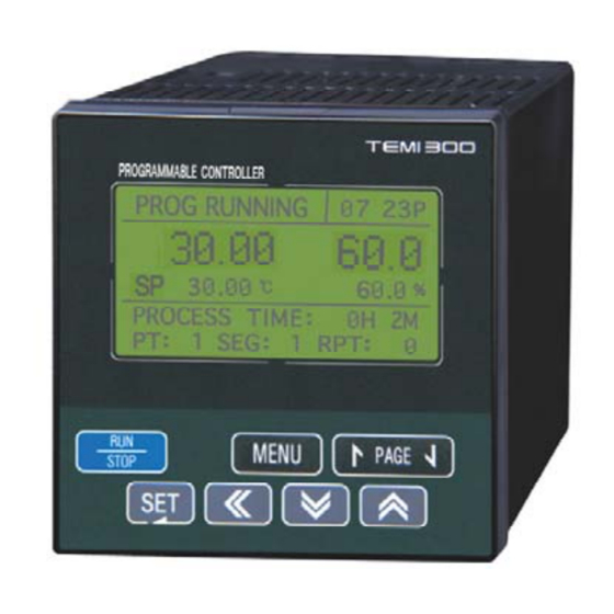
2. Control Keys and Display Control Keys ⊙ Contents Run / Stop controller (Pressing the key at least 3 sec.) Switching between running and main menu page Change the up level page on the parameter setting page Switches to next page on the same level Switches to previous page on the same level Change to page on the menu Switching between parameters or registering parameter settings... - Page 8 3. Basic Flow Map POWER ON FIX MODE TEMP & HUMI TEMP Only PROG MODE TEMP & HUMI TEMP Only MAIN MENU...
-
Page 9: Setup Menu
SETUP MENU... - Page 10 4. Setting Up Parameter in Each Group 4.1 FIX Mode FIX Mode is controlling Temperature & Humidity with fixed SP FIX STOP : Stop state SP : Set point (Setting by “SET” key) READY : Ready to running Start running by “RUN/STOP” key FIX running 1st screen FIX RUNNING : Fix running state PROCESS TIME : Running time...
-
Page 11: Prog Mode
4.2 PROG Mode PROG Mode is controlling Temperature & Humidity with programmed data PTNO : Set pattern No.(Set with “SET” key) SEGNO : Start segment No. READY : Ready to running Start running by “RUN/STOP” key PROG running 1st screen PROG RUNNING : Prog running state PROCESS TIME : Running time RPT : Repeat pattern No. - Page 12 Symbol Parameter Range Display Unit Default Edit T.EU T.EU(0.0 ∼ 100.0%) T.EU T.SP TEMP SP Always (0.0%) H.EU When HUMI H.SP HUMI SP H.EU(0.0 ∼ 100.0%) H.EU (0.0%) OPER=ON 0 ∼ 10 PTNO PATTERN NUMBER Always O*note 0∼100(00) SEGNO SEGMENT NUMBER Always 00H00M ∼...
- Page 13 4.3 MAIN Screen Operation & Setting 4.3.1 FUNCTION MENU KEY FUNCTION SET KEY SUB SET setting MAIN MENU FUNCTION SUB SETSET KEY SUB SET1, SUB SET2 (PAGE UP/DOWN KEY) OPER MODE : FIX / PROG PWR MODE : State mode after power failure Can be recognized over 3 sec.
- Page 14 Communication set MAIN MENU FUNCTION COMM SET SET KEY PROT : Protocol BPS : Speed (Bit per sec) PRTY : Parity S.BIT : Stop bit D.LEN : Data length ADDR : Address RP.TM : Response time AT TUNING set MAIN MENU ...
- Page 15 Symbol Parameter Range Display Unit Default Edit PROG, FIX PROG OPER MODE OPERATION MODE Always STOP, COLD, HOT STOP PWR MODE POWER MODE Always KEY LOCK KEY LOCK OFF, ON Always BUZZER BUZZER OFF, ON Always OFF, ON FUZZY FUZZY Always 0 ∼...
- Page 16 4.3.2 PROGRAM MENU KEY MAIN PROGRAM SET KEY EDIT SEG set MAIN MENU PROGRAM EDIT SEG SET KEY Set the temperature, humidity, time, TS1, TS2 and TS3 for each segment 1 : TS1(Time Signal1) 2 : TS2(Time Signal2) 3 : TS3(Time Signal3) EDIT PT set...
- Page 17 WAIT SET set MAIN MENU PROGRAM WAIT SET SET KEY TEMP ZONE : The range of temperature for waiting zone HUMI ZONE : The range of humidity for waiting zone WAIT TIME : Time for wait WAIT USE : Use / Not use Clear all of the patterns &...
- Page 18 Symbol Parameter Range Display Unit Default Edit 0.00 ∼ 99.59 0.00 WAIT TIME WAIT TIME(HH.MM) Always WAIT USE WAIT USE ON, OFF Always PT A.CLR OFF, ON Always ALL PATTERNS DELETE OFF, ON SEG A.CLR Always ALL SEGMENTS DELETE ※ Wait The wait function holds off the transition of segment until deviation is cleared up.
- Page 19 4.3.3 RESERVE RESERVE set MENU KEY MAIN RESERVE SET KEY NOW : Display present year, month, date and time which is set on SET DATE area RUN DATE : Set reserved starting year, month, date and time SET DATE : Set present year, month, date and time RESERVE : Use/not use Symbol...
- Page 20 4.3.4 GRAPH GRAPH set MENU KEY MAIN GRAPH SET KEY Display segment on pattern by graph for temperature & humidity PTN : Set the pattern No. for wished see SEG : Set the segment No. for display starting Symbol Parameter Range...
- Page 21 4.4 SETUP 4.4.1 INPUT SETUP set. MENU KEY MAIN SETUP SET KEY SET KEY Illuminate No. Password with UP, DOWN, SHIFT KEY SET KEY INPUT SET KEY TYPE : Set sensor type for temperature (PT-1, PT-2 or DCV) Resolution of PT-1 is higher than PT-2's RNG.HIGH/LOW : Rang of using temperature ▶...
- Page 22 T.BIAS : Set bias for temperature H.BIAS : Set bias for humidity high-frequency T.FL : Set for protect any effect from high frequency to temperature input H.FL : Set for protect any effect from high frequency to humidity input DRY TEMP : Temp of dry probe. WET TEMP : Temp of wet probe.
- Page 23 4.4.2 OUTPUT OUTPUT SET KEY TYPE : Output type for control temperature (SSR) DIRECT : Set reverse/forward for PID control CYCLE : Set output cycle ARW : The parameter to set deviation width to prevent overshoot. When the control output reaches High-Limited value, for preventing Overshoot by integral action, It is stoping ordinary action for integrals and shift for ARW(Anti-Reset Wind-Up).
- Page 24 KIND : Set type of humidity retransmission (PV, SP, MV) RNG.HIGH : Range of high RNG.LOW : Range of low PV : PV SP : SP MV : MV Symbol Parameter Range Display Unit Default Edit TEMP DIRECT REVERSE, FORWARD REVERSE DIRECT Always...
- Page 25 4.4.3 ON/OFF ON/OFF SET KEY ON/OFF mode1 for temperature HIGH.SP : Set low SP on ON/OFF HIGH.DIFF : Deviation value for high zone MIDDLE.SP : Set middle SP on ON/OFF LOW.SP : Set low SP on ON/OFF LOW.DIFF : Deviation value for low zone ON/OFF mode5 for temperature HIGH.SP : Set low SP on ON/OFF HIGH.DIFF : Deviation value for high zone...
- Page 26 1. T1∼T5, H1 (ON after set time.) ① NPV < LSP(LOW.SP) Output : OFF ② NPV > HSP(HIGH.SP) Output : OFF ③ LSP ≤ NPV < MSP(MIDDLE.SP) NPV ≥ NSP-LD(LOW.DIFF) Output : ON NPV < NSP-LD Output : OFF ④...
- Page 27 4.4.4 Inner Signal(IS) INNER SET KEY KIND : Set type of humidity retransmission (PV, SP, MV) RNG.HIGH(LOW) : Range for IS BAND : Direct of IS band (IN.B/OUT.B) DELAY. TM : IS delay time IS1 connected with 1ST REF, 2ND REF output INNER SIGNAL : There are 1 ∼...
- Page 28 4.4.5 ALARM ALARM SET KEY ALM1 MODE : Set alarm1 operation mode. ALM2 MODE : Set alarm2 operation mode. ALM3 MODE : Set alarm3 operation mode. ALM4 MODE : Set alarm4 operation mode. ALL : The alarm operation is performed always regardless of operation/stop.
- Page 29 (Table 1 : Alarm Type) Output Direct Standby Alarm Type Display Data AH.F PV Upper-Limit AL.F PV Lower-Limit DH.F Deviation Upper-Limit DL.F Deviation Lower-Limit DH.R Deviation Upper-Limit DL.R Deviation Lower-Limit DO.F Deviation Upper & Lower-Limit DI.F Deviation Upper & Lower-Limit Range AH.R PV Upper-Limit AL.R...
- Page 30 4.4.6 DO CONFIG DO CONFIG SET KEY DO CONFIG set (1st page) Set the relay number (1~12) for IS1∼6 and TS1∼3 DO CONFIG set (2nd page) Set the relay number (1~12) for ALARM1∼4, T.RUN and H.RUN DO CONFIG set (3rd page) Set the relay number (1~12) for T1∼T5 RUN also set the delay time for each items In case that time set, Delay time applied at every ON case...
- Page 31 DO CONFIG set (6th page) Set the relay number (1~12) for H.UP, H.SOK, and H.DN H.UP : Output until X% [X=TSP - set humidity] H.SOK : Output until X min [X=SOAK zone time - set time] H.DN : Output until X% [X=T.SP - set humidity] DO CONFIG set (7th page) DRAIN : Output on the zone that humidity is not used.
- Page 32 Symbol Parameter Range Display Unit Default Edit 0∼120(0:OUTPUT OFF) T6 SIGNAL Always T6 PARA T6 SIGNAL PARA 0.00∼99.59 MM.SS Always 00.00 H1 SIGNAL 0∼120(0:OUTPUT OFF) Always 0.00∼99.59 MM.SS 00.00 H1 PARA H1 SIGNAL PARA Always 0∼120(0:OUTPUT OFF) T.UP TEMP UP SIGNAL Always T.EUS T.EUS(0.0∼100.0%)
- Page 33 4.4.7 BIAS SET BIAS SET SET KEY Set bias for dry temperature P : Point (Boundary point) D : Bias value P=RH Actual Temperature P=P2 P=P1 Temperature after Bias P=RL (Figure 10 : Ex. Piece Bias Formula) Set bias for wet humidity P : Point (Boundary point) D : Bias value Set bias for relative humidity...
- Page 34 Symbol Parameter Range Display Unit Default Edit TEMP REFERENCE T.EU T.EU DP.RL Always (0.0%) BIAS RL T.EU(0.0∼100.0%) TEMP REFERENCE T.EU DP.P1 Always T.EU (100.0%) BIAS POINT1 RL≤DP.RL<DP.P1 TEMP REFERENCE T.EU DP.P2 Always T.EU (100.0%) BIAS POINT2 <DP.P2<DP.RH≤RH TEMP REFERENCE T.EU T.EU DP.PH Always...
- Page 35 4.4.8 DI NAME DI NAME SET KEY DI1 : RUN/STOP Not changeable DI2, 3, 4 NAME : SET KEY UP, DOWN key TOG GROUP : PAGE UP, PAGE DOWN key when name is illuminate Symbol Parameter Range Display Unit Default...
- Page 36 4.4.9 PASSWORD PASSWORD SET KEY Set the new password SET KEY UP, DOWN, SHIFT key SET KEY PROG OPER : ON edit “OPER MODE” , OFF not edit “OPER MODE” PROG OPER is not available on “RUN”. HUMI OPER : ON ...
- Page 37 4.4.10 PID SET PID SET SET KEY TEMP.RP1, RP2 : Boundary value on temperature span for PID zone HUMI.RP : Boundary value on humidity span for PID zone When use TEMP & HUMI TEMP only H.RP T.RP2 DRY.L T.RP1 DRY.H (100.0) (0.0)
-
Page 38: Proportional Band
Symbol Parameter Range Display Unit Default Edit 0.1 ∼ 99.9 % 50.0% TEMP.RP1 TEMP REFERENCE1 Always T.EU T.EU TEMP.RP2 TEMP REFERENCE2 Always T.EU (0.0+1digt ~100.0-1digit) (100%/2) H.EU H.EU(0.0 ~100.0) H.EU HUMI.RP HUMI REFERENCE Always (100%/2) PROPORTIONAL 0.1 ∼ 999.9 Display BAND 0 ∼... -
Page 39: Troubleshooting
4.5 TROUBLE SHOOTING If the system, which this controller (NOVA series) adapted, has troubles (if you used DI2~DI4), the page appear also display WARN at the item state as picture You must solve the error before reusing the controller, otherwise you are reach error again. - Page 40 5. Installation 5.1 Dimension & Panel Cutting Size (Unit : mm) 11.4 99.6 1mm~10mm (PANEL Thickness) N : Total unit...
- Page 41 5.2 How to install Mount 1) Cut the mounting panel as Section 5.1 PANEL CUTTING 2) Insert the unit from its back terminal board side 3) Attach the left and right brackets to the unit to fix the unit to the mounting panel.
-
Page 42: Terminal Specification
5.3 Power Cable Specification Applicable power source cable : Vinyl insulation cable KSC 3304 0.9~2.0 ㎟ 5.4 Terminal Specification Please use-tightening torque with insulating sleeve for M3.5 screws as shown in the following Figure: Φ3.0㎜ or more Note: When the screw is connected, its torque does not exceed 0.8 N·m. CAUTION ▶... - Page 43 5.5 Terminal Arrangement and External Wiring RELAY RLY1 RLY2 RLY3 RLY4 Capacity: Capacity:250V AC 1A RS485 Less then 24VDC 50mA 30V AC 1A RTX+ OUT1(+) RTX- OUT2(+) COM(-) MAX:9600bps INPUT 2 AOUT1(+) AOUT1(-) AOUT2(+) AOUT2(-) INPUT 1 RET 4~20mA DC POWER RELAY RLY5...
- Page 44 5.6 Grounding and Power Cable Connection ■ Use a cable 2 ㎟ or more thick for grounding with class 3 grounding (grounding resistance a 100Ω or less) or higher. Do not extend the grounding cable over 20m. ■ Ground from the ground terminal with a one-point contact. Do not wire between ground terminals.
-
Page 45: Analog Output Connection
(B) RETRANSMISSION 4∼20mADC, 600 Ω max SHIELD RET+ Control Valve RET- TEMI300 Class 3 Ground ▶ Before starting receiver( or recorder, etc) install/uninstall wiring, be sure to turn off the TEMI 300 or else you will get an electrical shock. CAUTION... - Page 46 5.9 External Contact Output Connection (RELAY) RLY_NO TEMI300 Before starting analog input wiring, be sure to turn off the system otherwise you might get an electrical shock. CAUTION 5.10 External Contact Output Connection(OPEN COLLECTOR : DO) load TEMI300 Power Supply 24V DC 50mA or less CAUTION 5.11 External Contact Input Connection (DI)
- Page 47 5.12 Use an Auxiliary Relay ■ If you INDUCTANCE(L) load like as AUXILIARY RELAY or SOLENOIDE VALVE, it might make go to wrong or out of order relay, please make sure insert to parallel circuit with CR FILTER(AC) or DIODE(DC) by SURGE SUPPRESSOR of avoiding sparks. ■...
- Page 48 1. Communication Overview TEMI300 is designed to establish a communication between upper-level computer and display via RS485 communication interface up to 31set. As below, there are some parameters when the TEMI 300 communicates. Parameter Value Description Basic Protocol Basic Protocol + Check Sum...
- Page 49 Ground Ground ■ The slave TEMI 300 could be connected up to 31set (MULTIDROP) ■ Termination (200Ω 1/4W) resistance must be connected on the both part of edge Before starting analog input wiring, be sure to turn off the system otherwise you might get an electrical shock.
- Page 50 3. Configuration of Command 3.1 Consist of Command It is basic communication command structure between upper-level computer and TEMI 300 ① ② ③ ④ ⑤ ⑥ ⑦ ⑧ ADDRESS COMMAND DATA by COMMAND ① Command start of text This code indicates the start of a command string with 0x02 ②...
-
Page 51: Communication Commands
3.2 Communication Commands There are two kinds of commands, Self-information and Read/Write commands in the TEMI 300 ① Self-information command Command Process Model name & Version ② Read/Write Command Command Process Reading D-Register orderly Reading D-Register Random Writing D-Register orderly... - Page 52 3.4 RSD Command This command for reading D-Register orderly ■ Transmission format Byte Parame Command Addr D-Reg.NO. SUM element number ■ Response Byte . . . Command Addr RSD dddd-1 dddd-2 . . . element dddd-(n-1) dddd-(n) - Parameter number : 1 ~ 32 - dddd : Indicates a character string in hexadecimal format Ex) When reading the D-Register from Temp PV(D0001) to Temp SP(D0002)
- Page 53 3.5 RRD Command This command for reading D-Register random ■ Transmission Format Byte . . . Para Command meter Addr RRD D-Reg.No1 D-Reg.No2 . . . element numb D-Reg.No(n-1) D-Reg.No(n) ■ Response Byte . . . Command Addr RRD dddd-1 dddd-2 .
- Page 54 3.6 WSD Command This command for writing D-Register orderly ■ Transmission Format Byte . . . Para Command meter Addr WSD D-Reg.No1 D-Reg.No2 . . . element numb D-Reg.No(n-1) D-Reg.No(n) ■ Response Byte Command Addr element - Parameter number : 1 ~ 32 - dddd : Indicates a character string in hexadecimal format Ex) When reading the D-Register from Temp SP(D0102), Humi SP(D0103)
- Page 55 3.7 WRD Command This command for writing D-Register random ■ Transmission Format Byte . . . Para Command meter Addr WRD D-Reg.No1 D-Reg.No2 . . . element numb D-Reg.No(n-1) D-Reg.No(n) ■ Response Byte Command Addr element - Parameter number : 1 ~ 32 - dddd : Indicates a character string in hexadecimal format Ex) When fix running, writing on Temp SP(D0102), Temp slope(D0106)
- Page 56 3.8 STD Command This command is register D-register which you want to using at the TEMI 300 ■ Transmission Format Byte . . . Para Command meter Addr STD D-Reg.No1 D-Reg.No2 . . . element numb D-Reg.No(n-1) D-Reg.No(n) ■ Response Byte 수...
- Page 57 3.9 CLD Command This command is reading D-register, which was resisted by STD Command at the TEMI 300 ■ Transmission Format Byte Command Addr element ■ Response Byte . . . Command Addr CLD dddd-1 dddd-2 . . . element...
- Page 58 4. D-REGISTER D-Register is group of data which can using with communication all of TEMI 300s condition. Each group has 100 registers and these are classified as follows; D-Register Range Group Description Read Write D0001 ~ D0099 PROCESS BASIC PROCESS DISPLAY ×...
- Page 59 4.1 PROCESS Process group has basic data. It has Bit Map (Display data by Bit) as follow; NOW_STS IS_STS TS_STS AL_STS UO_STS (D0010) (D0012) (D0013) (D0014) (D0016) RESET INNER SIGNAL 1 TIME SIGNAL 1 ALARM 1 RELAY 1 FIX_RUN INNER SIGNAL 2 TIME SIGNAL 2 ALARM 2 RELAY 2...
- Page 60 ■ Share running D-Register D-Register Symbol Description D0001 TEMP_NPV PRESENT TEMP PV D0002 TEMP_NSP PRESENT TEMP SP D0003 WET_NPV PRESENT WEB VERB TEMP PV D0004 WET_NSP PRESENT WEB VERB TEMP SP D0005 HUMI_NPV PRESENT HUMI PV D0006 HUMI_NSP PRESENT HUMI SP D0007 TEMP_MVOUT TEMP MV OUTPUT...
- Page 61 4.2 FUNCTION FUNCTION is consisted D-Register for operation ■ PROGRAM Running D-Register D-Register Symbol Description D0100 SET_PTNO Program pattern number for running D0122 TEMP_WAIT_ZONE Temp wait zone D0123 HUMI_WAIT_ZONE Humi wait zone D0124 WAIT_TIME Wait time ■ FIX running D-Register D-Register Symbol Description...
- Page 62 PWRMODE COLD COLD MODE HOT MODE For PROG RUN's (or FIX RUN) through communication, TEMI 300 must be STOP(PROG STOP/FIX STOP) Ex) TEMI 300 should be PROG STOP(D0104 = 0001, D0101 = 0004) for switching FIX RUN TO PROG RUN...
- Page 63 4.3 RESERVATION RESERVATION group is consisted confirm time, setting & reservation time D-Register ■ Setting Time D-Register D-Register Symbol Description Read Write D0201 NOW_YEAR PRESENT TIME (YEAR) D0202 NOW_MONTH PRESENT TIME (MONTH) D0203 NOW_DAY PRESENT TIME (DAY) D0204 NOW_HOUR PRESENT TIME (HOUR) D0205 NOW_MIN PRESENT TIME (MIN)
- Page 64 4.4 IS/ALARM IS & ALARM group is consisted Inner D-Register for Signal & Alarm setting ■ Setting IS D-Register D-Register Symbol Description D0305 IS1_BAND IS1 RANGE DIRECTION D0306 IS1_KIND IS1 RUNNING ITEM D0307 IS1_HIGH IS1 RANGE HIGH D0308 IS1_LOW IS1 RANGE LOW D0309 IS1_DELAY_TM IS1 DELAY TIME...
- Page 65 4.5 PID PID GROUP is consisted D-Register for setting PID ■ Setting PID D-Register D-Register Symbol Description D0500 TEMP_PB1 PROPORTIONAL OPERATION TIME FOR TEMP PID1 CONTROL D0501 TEMP_TI1 INTEGRATION TIME FOR TEMP PID1 CONTROL D0502 TEMP_TD1 DERIVATION TIME FOR TEMP PID1 CONTROL D0503 TEMP_OH1 THE HIGH RANGE OF TEMP PID 1...
- Page 66 4.6 OUTPUT OUTPUT GROUP is consisted D-Register for setting Control Output ■ Setting OUTPUT D-Register D-Register Symbol Description D0800 TEMP_OT TEMP OUTPUT TYPE D0801 TEMP_DR TEMP DIRECTION D0802 TEMP_CT TEMP CYCLE D0803 TEMP_ARW TEMP ARW D0806 TEMP_ATGAIN TEMP AT GAIN D0807 TEMP_ATGAIN HUMI AT GAIN...
- Page 67 D-Register Symbol Description D0834 DOCON_T5 T5 SIGNAL CONTACT OUTPUT D0835 DOCON_T6 T6 SIGNAL CONTACT OUTPUT D0836 DOCON_T5TM T5 SIGNAL TIME D0837 DOCON_T6TM T6 SIGNAL TIME D0858 DOCON_H1 H1 SIGNAL CONTACT OUTPUT D0859 DOCON_T1TM T1 SIGNAL TIME ..
- Page 68 4.7 INPUT INPUT GROUP is consisted D-Register for setting Input ■ Setting INPUT D-Register D-Register Symbol Description D0900 TEMP_IN TEMP INPUT TYPE D0901 TEMP_RH TEMP HIGH RANGE D0902 TEMP_RL TEMP LOW RANGE D0904 TEMP_FILTER TEMP FILTER D0905 TEMP_SH TEMP HIGH SCALE D0906 TEMP_SL TEMP LOW SCALE...
- Page 69 4.8 PROGRAM PROGRAM GROUP is consisted D-Register for setting Program Pattern ■ Setting PROGRAM PATTERN setting D-Register D-Register Symbol Description D1000 PT_SS1 PATTERN 1 START SEGMENT NO. D1001 PT_ES1 PATTERN 1 END SEGMENT NO. D1002 PT_RPT1 PATTERN 1 REPEAT NO. OF TIME D1003 PT_JP1 PATTERN NO AFTER RUNNING PATTERN 1...
- Page 70 4.9 ON/OFF ON/OFF GROUP is consisted D-Register for setting ON/OFF SIGNAL ■ Setting ON/OFF SIGNAL D-Register D-Register Symbol Description D1700 ONF_LOWSP_T1 LOW SP_T1 D1701 ONF_MIDSP_T1 MIDDLE SP_T1 D1702 ONF_HIGHSP_T1 HIGH SP_T1 D1703 ONF_DIFH_T1 HIGH DIFFERENCE_T1 D1704 ONF_DIFL_T1 LOW DIFFERENCE_T1 D1720 ONF_LOWSP_T3 LOW SP_T5 D1721...
- Page 71 D-Register 0000∼0599 PROCESS FUNCTION RESERVATION ALARM TEMP_PID SET_PTNO RESERVE AL1_ITEM TEMP_PB1 TEMP_NPV STATUS_MODE NOW_YEAR AL2_ITEM TEMP_TI1 TEMP_NSP FIX_TEMP_SP NOW_MONTH AL3_ITEM TEMP_TD1 WET_NPV FIX_HUMI_SP NOW_DAY AL4_ITEM TEMP_OH1 WET_NSP OP_MODE NOW_HOUR TEMP_OL1 HUMI_NPV PWR_MODE NOW_MIN IS1_BAND AL1_KIND TEMP_MR1 HUMI_NSP TEMP_SLOPE RUN_YEAR IS1_KIND AL2_KIND TEMP_PB2 TEMP_MVOUT...
- Page 72 PROCESS FUNCTION RESERVATION ALARM TEMP_PID TEMP_OL6 IS6_DELAY_TM TEMP_MR6 PREV_TEMP_TSP NOW_TEMP_TSP PREV_HUMI_TSP NOW_HUMI_TSP NOW_SEG_TIME...
- Page 73 PROCESS FUNCTION RESERVATION ALARM TEMP_PID...
- Page 74 D-Register 0600∼1199 HUMI_PID COMM OUTPUT INPUT PROGRAM PROG_INFO1 1000 1100 HUMI_PB1 PROTOCOL TEMP_OT TEMP_IN PT_SS1 SEG_TSP1 HUMI_TI1 BAUD_RATE TEMP_DR TEMP_RH PT_ES1 SEG_TSP2 HUMI_TD1 PARITY TEMP_CT TEMP_RL PT_RPT1 SEG_TSP3 HUMI_OH1 STOP_BIT TEMP_ARW TEMP_BIAS PT_JP1 SEG_TSP4 HUMI_OL1 DATA_LENGTH TEMP_SH SEG_TSP5 HUMI_MR1 ADDRESS TEMP_SL SEG_TSP6 HUMI_PB2...
- Page 75 HUMI_PID COMM OUTPUT INPUT PROGRAM PROG_INFO1 1000 1100 HUMI_OL6 DOCON_T5 SEG_TSP35 HUMI_MR6 DOCON_T6 SEG_TSP36 DOCON_T5TM SEG_TSP37 DOCON_T6TM SEG_TSP38 SEG_TSP39 DOCON_IS1 SEG_TSP40 DOCON_IS2 DP_RL PT_SS5 SEG_TSP41 DOCON_IS3 DP_P1 PT_ES5 SEGT_TSP42 DOCON_IS4 DP_P2 PT_RPT5 SEG_TSP43 DOCON_IS5 DP_RH PT_JP5 SEG_TSP44 DOCON_IS6 DD_RL SEG_TSP45 DOCON_TS1 DD_P1 SEG_TSP46...
- Page 76 HUMI_PID COMM OUTPUT INPUT PROGRAM PROG_INFO1 1000 1100 SEG_TSP70 DOCON_TDN_P DOCON_HUP PT_SS8 SEG_TSP71 DOCON_HSK PT_ES8 SEG_TSP72 DOCON_HDN PT_RPT8 SEG_TSP73 PT_JP8 SEG_TSP74 DOCON_HUP_P SEG_TSP75 DOCON_HSK_P SEG_TSP76 DOCON_HDN_P DOCON_DRAIN SEG_TSP77 DOCON_ERR SEG_TSP78 SEG_TSP79 DOCON_PTEND DOCON_1REF SEG_TSP80 DOCON_2REF PT_SS9 SEG_TSP81 PT_ES9 SEG_TSP82 DOCON_DRAIN_P PT_RPT9 SEG_TSP83 DOCON__ERR_P...
- Page 77 D-Register 1200∼1799 PROG_INFO2 PROG_INFO3 PROG_INFO4 PROG_INFO5 PROG_INFO6 ON/OFF 1200 1300 1400 1500 1600 1700 SEG_HSP1 SEG_TM1 SEG_TS11 SEG_TS21 SEG_TS31 ONF_LOWSP_T1 SEG_HSP2 SEG_TM2 SEG_TS12 SEG_TS22 SEG_TS32 ONF_MIDSP_T1 SEG_HSP3 SEG_TM3 SEG_TS13 SEG_TS23 SEG_TS33 ONF_HIGHSP_T1 SEG_HSP4 SEG_TM4 SEG_TS14 SEG_TS24 SEG_TS34 ONF_DIFH_T1 SEG_HSP5 SEG_TM5 SEG_TS15 SEG_TS25 SEG_TS35...
- Page 78 PROG_INFO2 PROG_INFO3 PROG_INFO4 PROG_INFO5 PROG_INFO6 1200 1300 1400 1500 1600 1700 SEG_HSP35 SEG_TM35 SEG_TS135 SEG_TS235 SEG_TS335 ONF_DIFL_H1 SEG_HSP36 SEG_TM36 SEG_TS136 SEG_TS236 SEG_TS336 SEG_HSP37 SEG_TM37 SEG_TS137 SEG_TS237 SEG_TS337 SEG_HSP38 SEG_TM38 SEG_TS138 SEG_TS238 SEG_TS338 SEG_HSP39 SEG_TM39 SEG_TS139 SEG_TS239 SEG_TS339 SEG_HSP40 SEG_TM40 SEG_TS140 SEG_TS240 SEG_TS340 SEG_HSP41...
- Page 79 PROG_INFO2 PROG_INFO3 PROG_INFO4 PROG_INFO5 PROG_INFO6 1200 1300 1400 1500 1600 1700 SEG_HSP70 SEG_TM70 SEG_TS170 SEG_TS270 SEG_TS370 SEG_HSP71 SEG_TM71 SEG_TS171 SEG_TS271 SEG_TS371 SEG_HSP72 SEG_TM72 SEG_TS172 SEG_TS272 SEG_TS372 SEG_HSP73 SEG_TM73 SEG_TS173 SEG_TS273 SEG_TS373 SEG_HSP74 SEG_TM74 SEG_TS174 SEG_TS274 SEG_TS374 SEG_HSP75 SEG_TM75 SEG_TS175 SEG_TS275 SEG_TS375 SEG_HSP76 SEG_TM76...
- Page 80 Further information contact Samwontech SAMWONTECH CO., LTD. 202-703, Buchon Techno-park, Yakdae-dong, Wonmi-gu, Buchon, Gyeonggi-do, Korea 420-733 TEL: +82-32-326-9120, 9121 FAX: +82-32-326-9119 http:// www.samwontech.com E-mail: webmaster@samwontech.com The contents of this document are subject to change without prior notice. Printed in Korea : Nov. 2003(A) All Rights Reserved.
Need help?
Do you have a question about the TEMI 300 and is the answer not in the manual?
Questions and answers