Advertisement
Quick Links
Advertisement

Subscribe to Our Youtube Channel
Related Manuals for Insportline IN 9361 Baraton


Summary of Contents for Insportline IN 9361 Baraton
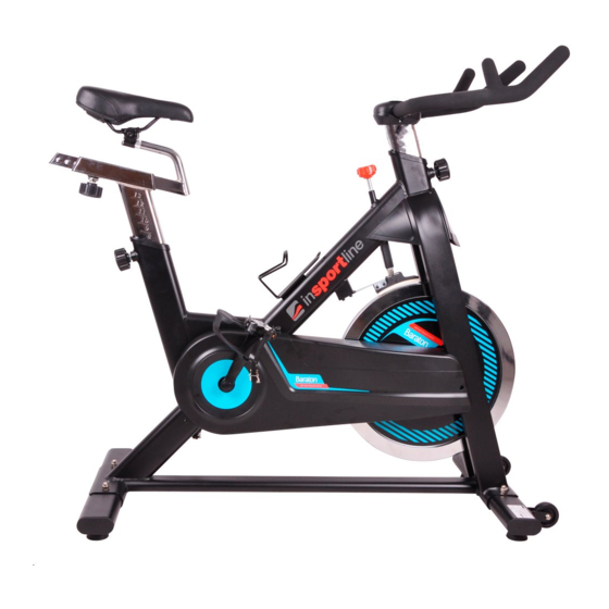
- Page 1 USER MANUAL – EN IN 9361 Spinning Bike inSPORTline Baraton...
-
Page 2: Table Of Contents
CONTENTS IMPORTANT SAFETY INFORMATION......................3 EXPLODED VIEW (A) ............................4 EXPLODED VIEW (B) ............................5 PARTS LIST ................................6 ASSEMBLING INSTRUCTIONS ......................... 8 TERMS AND CONDITIONS OF WARRANTY, WARRANTY CLAIMS ............10... -
Page 3: Important Safety Information
IMPORTANT SAFETY INFORMATION Please keep this manual in a safe place for reference. 1. It is important to read this entire manual before assembling and using the equipment. Safe and efficient use can only be achieved if the equipment is assembled, maintained and used properly. It is your responsibility to ensure that all users of the equipment are informed of all warnings and precautions. -
Page 4: Exploded View (A)
EXPLODED VIEW (A) -
Page 5: Exploded View (B)
EXPLODED VIEW (B) -
Page 6: Parts List
PARTS LIST NAME SPECIFICATION Main frame Seat post 30*70*1.5T*438L ■30*30*2.0T*320L Seat sliding post Handlebar post 30*70*1.5T*260L ●φ25*2T Handlebar Front stabilizer 40*80*1.5T*500L Rear stabilizer 40*80*1.5T*500L Adjusting knob M16*1.5 Suit 38*38*1.5T* INNER Sleeve 30*30 Bushing Suit 30*30*1.5T tube Saddle φ65.13*16 gear Small sprocket wheel φ42*5.0 Locking ring ф26*ф20.2*6T... - Page 7 Flat washer Outer cover Bolt M5*15 Brake blockbuster 34.5*23.5*2.0 Brake spacer 34*24*3 Brake bracket Felt wool 108*28*6 Screw M5*30 Nylon nut Bottle holder Screw M5*15L M12*P1.25 ф35*ф12.5*2.0 Washer φ20*φ12.2*22L Short step tube φ15*146*M12*P1.25 Flywheel axis Bearing 6001RS φ450*35W Flywheel φ20*φ12.2*25L Long step tube Bolt M6*50...
-
Page 8: Assembling Instructions
TOOLS SPANNER: ASSEMBLING INSTRUCTIONS STEP 1: Attach the rear stabilizer (pt. 7) to the main frame (pt. 1) using two sets of domed nuts (pt. 28), washers (pt. 16) and bolts (pt. 69) and tighten. STEP 2: Attach the front stabilizer (pt. 6) to the main frame (pt. 1) using two sets of domed nuts (pt. - Page 9 STEP 4: Slacken the adjusting knob (pt. 8) and pull back and locate the handlebar post (pt. 4) in the housing on the main frame (pt. 1). Align the correct holes at the desired height until the “stop” mark and then tighten the adjusting knob (pt.
-
Page 10: Terms And Conditions Of Warranty, Warranty Claims
STEP 8: Fix the seat (pt. 11) to the seat sliding post (pt. 3) as shown, and tighten the bolts around the screws under the seat. You will have to loosen the knurled section of the adjustment knob (pt. 8) and pull the knob back before sliding the sliding seat post (pt. - Page 11 Improper maintenance, improper placement, damages caused by low or high temperature, water, inappropriate pressure, shocks, intentional changes in design or construction etc. Warranty Claim Procedure The Buyer is obliged to check the Goods delivered by the Seller immediately after taking the responsibility for the Goods and its damages, i.e.
- Page 12 Date of Sale: Stamp and Signature of Seller:...
Need help?
Do you have a question about the IN 9361 Baraton and is the answer not in the manual?
Questions and answers