Table of Contents
Advertisement
Quick Links
Advertisement
Table of Contents

Related Manuals for Supermicro X10SRG-F


Summary of Contents for Supermicro X10SRG-F
- Page 1 X10SRG-F USER’S MANUAL Revision 1.0c...
- Page 2 This product, including software and docu- mentation, is the property of Supermicro and/or its licensors, and is supplied only under a license. Any use or reproduction of this product is not allowed, except as expressly permitted by the terms of said license.
-
Page 3: About This Motherboard
It provides information for the installation and use of the X10SRG-F motherboard. About This Motherboard X10SRG-F Motherboard supports a single Intel ® E5-2600/1600 Series Processor (LGA 2011 socket). With the Intel ® C612 chipset built in, the X10SRG- F motherboard offers exceptional system performance and storage capability. -
Page 4: Conventions Used In The Manual
X10SRG-F Motherboard User’s Manual Conventions Used in the Manual Special attention should be given to the following symbols for proper installation and to prevent damage done to the components or injury to yourself: Warning: Critical information to prevent damage to the components or data loss. -
Page 5: Contacting Supermicro
Super Micro Computer, Inc. 980 Rock Ave. San Jose, CA 95131 U.S.A. Tel: +1 (408) 503-8000 Fax: +1 (408) 503-8008 Email: marketing@supermicro.com (General Information) support@supermicro.com (Technical Support) Web Site: www.supermicro.com Europe Address: Super Micro Computer B.V. Het Sterrenbeeld 28, 5215 ML... -
Page 6: Table Of Contents
X10SRG-F Motherboard User’s Manual Table of Contents Preface Chapter 1 Introduction Overview ......................1-1 Checklist ......................1-1 Motherboard Features ..................1-7 Chipset Overview ..................1-10 Intel C612 Chipset Features ................. 1-10 Special Features ....................1-11 Recovery from AC Power Loss ..............1-11 PC Health Monitoring ..................1-11... - Page 7 Table of Contents Motherboard I/O Backpanel ................2-14 Universal Serial Bus (USB) ..............2-15 Ethernet Ports (LAN1/LAN2) ..............2-16 IPMI Port (IPMI) ..................2-16 Serial Ports ....................2-16 VGA Connector (VGA) ................2-17 Unit Identifier Switch (UID) ............... 2-17 Front Control Panel ..................2-18 Front Control Panel Pin Definitions...............
- Page 8 X10SRG-F Motherboard User’s Manual BIOS Recovery (JBR1) ................2-33 C Bus for VRM ..................2-33 Onboard Indicators ..................2-34 LAN Port LEDs ..................2-34 IPMI Heartbeat LED (LEDM1)..............2-34 Unit Identification LED (LE1) ..............2-35 Onboard Power LED (LE2) ..............2-35 SATA Connections ..................
- Page 9 Table of Contents Quiet Boot ....................4-4 AddOn ROM Display Mode ................ 4-4 Bootup Num-Lock ..................4-5 Wait For 'F1' If Error ................... 4-5 INT19 (Interrupt 19) Trap Response ............4-5 Re-try Boot ....................4-5 Power Configuration ..................4-5 DeepSx Power Policies ................4-5 GP27 Wake From DeepSx .................
- Page 10 X10SRG-F Motherboard User’s Manual EHCI Hand-Off ..................4-16 Port 60/64 Emulation ................4-16 USB 3.0 Support ..................4-16 EHCI1 ....................... 4-16 EHCI2 ....................... 4-16 XHCI Pre-Boot Driver ................4-16 SATA Configuration ..................4-16 SATA Controller ..................4-16 Configure SATA as ................... 4-17 ...
- Page 11 Table of Contents PXE Boot Wait Time ................. 4-23 Media Detect Time ................... 4-24 Serial Port 1 Configuration ..............4-24 Serial Port 1 ..................... 4-24 Device Settings ..................4-24 Change Port 1 Settings ................4-24 Serial Port 2 Configuration ..............4-24 Serial Port 2 .....................
- Page 12 X10SRG-F Motherboard User’s Manual UEFI SATA RAID ..................4-35 Event Logs ....................4-36 Change SMBIOS Event Log Settings ............4-36 Enabling/Disabling Options ..............4-36 SMBIOS Event Log .................. 4-36 Runtime Error Logging Support ............... 4-36 Memory Corrected Error Enabling (Available when the item above-Runtime Error Logging Support is set to Enable) ..........
- Page 13 Table of Contents Boot Option File Path ................4-43 Delete Boot Option ................4-43 Hard Disk Drive BBS Priorities ............. 4-43 Network Drive BBS Priorities ..............4-44 USB Key Drive BBS Priorities............... 4-44 UEFI USB Key Drive BBS Priorities ............. 4-44 ...
- Page 14 X10SRG-F Motherboard User’s Manual Notes...
-
Page 15: Chapter 1 Introduction
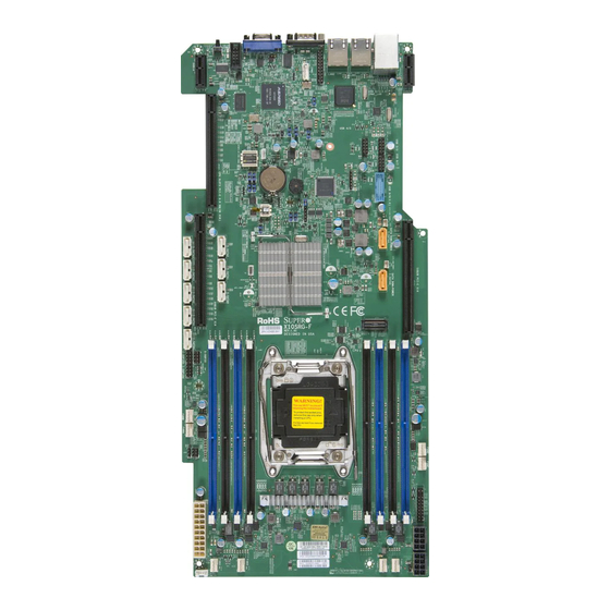
Checklist Congratulations on purchasing your computer motherboard from an acknowledged leader in the industry. Supermicro boards are designed with the utmost attention to detail to provide you with the highest standards in quality and performance. Please check that the following items have all been included with your motherboard. - Page 16 X10SRG-F Motherboard User’s Manual X10SRG-F Motherboard Image Note: All graphics shown in this manual were based upon the latest PCB Revision available at the time of publishing of the manual. The motherboard you've received may or may not look exactly the same as the graphics...
- Page 17 Chapter 1: Introduction X10SRG-F Motherboard Layout COM1 JUIDB1 UID-SW COM2 LAN2 LAN1 USB 0/1(3.0) SXB1A IPMI_LAN SXB2A i350 LEDM1 JPL1 JBRSET1 JPG1 USB 4/5 JSTBY1 USB 6/7 USB 8/9(3.0) Intel C610 JBT1 JITP1 X10SRG-F REV:1.01 DESIGNED IN USA LGA2011-3 JVR1...
- Page 18 X10SRG-F Motherboard User’s Manual X10SRG-F Motherboard Quick Reference JIPMB1 LAN2 USB0/1 VGA1 COM1 LAN1 IPMI LAN COM1 JUIDB1 SXB2A UID-SW COM2 SXB1A COM2 LAN2 LAN1 USB 0/1(3.0) SXB1A IPMI_LAN JTPM1 SXB2A LEDM1 i350 LEDM1 JPL1 JPL1 JBRSET1 JPB1 JOH1 JPG1...
- Page 19 S-SATA0~S-SATA3 SATA 3.0 Connectors via PCH (6Gb/s) SLOT3 Slot for Supemicro riser card P/N RSC-R1UG-UR Internal Speaker/Buzzer SXB1A, SXB1B Slot for Supermicro riser card P/N RSC-R1UG-E16-UP, RSC-R1UG-2E8G-UP SXB2A, SXB2B Slot for Supermicro riser card P/N RSC-R1UG-E16R-UP, RSC-R1UG-2E8GR-UP I-SGPIO1, I-SGPIO2, Serial Link General Purpose I/O Headers (5V Gen1/Gen...
- Page 20 X10SRG-F Motherboard User’s Manual X10SRG-F Motherboard Jumpers Jumper Description Default JBR1 BIOS Recovery Pins 1-2 (Normal) JBRSET1 FIQ Request Pins 1-2 (Normal) JBT1 CMOS Clear See Chapter 2 JI2C1/JI2C2 SMB to PCI Slots Pins 1-2 (Enabled) JPB1 BMC Enable Pins 1-2 (Enabled)
-
Page 21: Motherboard Features
Chapter 1: Introduction Motherboard Features Single Intel ® E5-2600/1600 Series Processor (LGA 2011 Socket R3) Note: Both E5-2600v4 and E5-1600v4 re- quire Revision 2.0 BIOS (or higher). Memory Eight (8) DIMM slots support up to 256GB RDIMM or 512 LRDIMM of DDR4 ECC memory at 2400 MHz (max.). DIMM sizes RDIMM 2GB, 4GB, 8GB, 16GB, 32GB, 64GB... - Page 22 X10SRG-F Motherboard User’s Manual BIOS 128 Mb SPI AMI BIOS SM Flash BIOS ® Plug & Play, DMI 2.3, ACPI 1.0/2.0/3.0, USB Keyboard and SMBIOS 2.5 Power Configuration ACPI/ACPM Power Management CPU Fan Auto-off in Sleep Mode Power-on mode for AC power recovery PC Health Monitoring CPU &...
-
Page 23: System Block Diagram
Chapter 1: Introduction X10SRG-F Motherboard Block Diagram VR12.5 #0-8 #0-4 5 PHASE #0-7 #0-3 145W #0-6 #0-2 #0-5 #0-1 Skt-R3 LGA2011-3 DMI2 PCI-E X8 Gen3 PCIe3.0 x8 SLOT3 (x8 in x16) PCI-E X16 Gen3 SLOT2 PCIe3.0 x16 PCI-E X16 Gen3 SLOT1 PCIe3.0 x16... -
Page 24: Chipset Overview
X10SRG-F Motherboard User’s Manual Chipset Overview The Intel ® C612 series is a single chip solution that is designed for dedicated servers and workstations. It supports high-speed SATA and advanced require- ments for Intel ® Xeon platforms. Intel C612 Chipset Features •... -
Page 25: Special Features
Chapter 1: Introduction Special Features Recovery from AC Power Loss Basic I/O System (BIOS) provides a setting for you to determine how the system will respond when AC power is lost and then restored to the system. You can choose for the system to remain powered off (in which case you must press the power switch to turn it back on), or for it to automatically return to a power-on state. -
Page 26: System Resource Alert
X10SRG-F Motherboard User’s Manual System Resource Alert This feature is available when the system is used with SuperDoctor ® 5 in the Windows ® OS environment or used with SuperDoctor II in Linux. SuperDoctor is used to notify the user of certain system events. For example, you can also configure SuperDoctor to provide you with warnings when the system temperature, CPU temperatures, voltages and fan speeds go beyond predefined thresholds. - Page 27 Chapter 1: Introduction strongly recommended that you use a high quality power supply that meets ower sup- ply Specifications 2.02 or above. It must also be SSI compliant. (For more information, please refer to the web site at http://www.ssiforum.org/). Additionally, in areas where noisy power transmission is present, you may choose to install a line filter to shield the computer from noise.
- Page 28 X10SRG-F Motherboard User’s Manual Notes 1-14...
-
Page 29: Chapter 2 Installation
Chapter 2: Installation Chapter 2 Installation Static-Sensitive Devices Electrostatic-Discharge (ESD) can damage electronic com ponents. To avoid dam- aging your system board, it is important to handle it very carefully. The following measures are generally sufficient to protect your equipment from ESD. Precautions •... -
Page 30: Motherboard Installation
X10SRG-F Motherboard User’s Manual Motherboard Installation All motherboards have standard mounting holes to fit different types of chassis. Make sure that the locations of all the mounting holes for both motherboard and chassis match. Although a chassis may have both plastic and metal mounting fas- teners, metal ones are highly recommended because they ground the motherboard to the chassis. -
Page 31: Installing The Motherboard
Chapter 2: Installation Installing the Motherboard 1. Install the I/O shield into the chassis. 2. Locate the mounting holes on the motherboard. 3. Locate the matching mounting holes on the chassis. Align the mounting holes on the motherboard against the mounting holes on the chassis. 4. -
Page 32: Processor And Heatsink Installation
CPU socket cap is in place and none of the socket pins are bent; otherwise, contact your retailer immediately. • Refer to the Supermicro website for updates on CPU support. Opening the LGA2011 Socket 1. There are two load levers on the LGA2011 socket. To open the socket cover, first press and release the load lever labeled 'Open 1st'. - Page 33 Chapter 2: Installation 2. Press the second load lever labeled 'Close 1st' to release the load plate which covers the CPU socket from its locking position. Press down on Load Lever 'Close 1st' Pull lever away from the socket 3. With the 'Close 1st' lever fully retracted, gently push down on the 'Open 1st' lever to open the load plate.
-
Page 34: Installing The Lga2011 Processor
X10SRG-F Motherboard User’s Manual Installing the LGA2011 Processor 1. With the LGA 2011 socket open, remove the 'WARNING' plastic cap using your fingers. Socket Keys CPU Keys 2. Use your thumb and index finger to hold the CPU on its edges. Align the CPU keys (semi-circle cutouts) against the socket keys. - Page 35 Chapter 2: Installation 3. Once it is aligned, carefully lower the CPU straight down into the socket. (Do not drop the CPU on the socket. Do not move the CPU horizontally or verti- cally. 4. Do not rub the CPU against the surface or against any pins of the socket to avoid damaging the CPU or the socket.) 5.
-
Page 36: Installing A Passive Cpu Heatsink
X10SRG-F Motherboard User’s Manual Installing a Passive CPU Heatsink 1. Do not apply any thermal grease to the heatsink or the CPU die -- the re- quired amount has already been applied. 2. Place the heatsink on top of the CPU so that the four mounting holes are aligned with those on the Motherboard's and the Heatsink Bracket under- neath. -
Page 37: Removing The Heatsink
Chapter 2: Installation Removing the Heatsink Warning: We do not recommend that the CPU or the heatsink be removed. However, if you do need to uninstall the heatsink, please follow the instructions below to prevent damage to the CPU or the CPU socket. 1. -
Page 38: Installing Ddr4 Memory
Exercise extreme care when installing or removing DIMM JBRSET1 JPG1 modules to prevent any possible damage. USB 4/5 JSTBY1 USB 6/7 Note: Check the Supermicro website for recommended memory modules. USB 8/9(3.0) DIMM Installation Intel C610 JBT1 1. Insert the desired number of DIMMs JITP1... -
Page 39: Memory Support
Chapter 2: Installation Memory Support The X10SRG-F motherboard supports up to 256GB RDIMM or 512 LRDIMM of DDR4 ECC memory at 2400 MHz (max.) in eight (8) memory slots. Please refer to the illustration below and the table on the next page:... - Page 40 X10SRG-F Motherboard User’s Manual Memory Population Guidelines When installing memory modules, the DIMM slots should be populated in the follow- ing order: DIMMA1, DIMMB1, DIMMC1, DIMMD1 then DIMMA2, DIMMB2, DIMMC2, DIMMD2. • Always use DDR4 DIMM modules of the same size, type and speed.
- Page 41 Chapter 2: Installation Populating RDIMM/LRDIMM DDR4 Memory Modules for the E5- 2600v3-based Motherboard Speed (MT/s); Voltage (V); Slot Per Channel (SPC) and DIMM Per Channel (DPC) DIMM Capacity Ranks Per (GB) DIMM and Type 1 Slot Per Data 2 Slots Per Channel Channel Width 1DPC...
-
Page 42: Connectors/Io Ports
X10SRG-F Motherboard User’s Manual Connectors/IO Ports The I/O ports are color coded in conformance with the industry standards. See the figure below for the colors and locations of the various I/O ports. Motherboard I/O Backpanel COM1 JUIDB1 UID-SW COM2 LAN2 LAN1 USB 0/1(3.0) -
Page 43: Universal Serial Bus (Usb)
Chapter 2: Installation Universal Serial Bus (USB) Front Panel USB (2.0) Header Pin Definitions Two (2) Universal Serial Bus 3.0 ports Pin # Definition Pin # Definition are located on the I/O back panel. There are also six (6) USB 2.0 ports USB_PN2 USB_PN3 and two (2) USB 3.0 ports on the... -
Page 44: Ethernet Ports (Lan1/Lan2)
X10SRG-F Motherboard User’s Manual Ethernet Ports (LAN1/LAN2) LAN Ports Pin Definition Two Ethernet ports (LAN1/LAN2) are Pin# Definition Pin# Definition located next to the USB ports on the TD0- SGND I/O backpanel. These ports provide TD0+ P3V3SB networking connectivity with speeds... -
Page 45: Vga Connector (Vga)
Chapter 2: Installation VGA Connector (VGA) VGA Pin Definitions A Video (VGA/CRT) connector is Pin# Definition Pin# Definition located next to COM Port1 on the I/O Ground backpanel. This connector is used to Green provide video and CRT display. Blue MS1: SDA (DDC Data) HSYNC Unit Identifier Switch (UID) -
Page 46: Front Control Panel
JPL1 cated on a control panel at the front of the chassis. These connectors are designed specifically for use with Supermicro server chassis. See the figure below for the JBRSET1 descriptions of the various control panel buttons and LED indicators. Refer to the JPG1 following section for descriptions and pin definitions. -
Page 47: Front Control Panel Pin Definitions
Chapter 2: Installation Front Control Panel Pin Definitions Power LED Power LED Pin Definitions (JF1) Status Power LED Pin# Definition State Definition The Power LED connection is located System Off on pins 15 and 16 of JF1. Refer to the Ground System Running table on the right for pin definitions. -
Page 48: Nic1/Nic2 (Lan1/Lan2)
X10SRG-F Motherboard User’s Manual NIC1/NIC2 (LAN1/LAN2) LAN1/LAN2 LED NIC LED Pin Definitions (JF1) Status The NIC (Network Interface Control- Pin# Definition State Definition ler) LED connection for LAN port 1 9/11 No Activity is located on pins 11 and 12 of JF1,... -
Page 49: Nmi Button
Chapter 2: Installation NMI Button NMI Button Pin Definitions (JF1) The non-maskable interrupt button Pin# Definition header is located on pins 19 and 20 Control of JF1. Refer to the table on the right Ground for pin definitions. Reset Button The Reset Button connection is lo- Reset Button cated on pins 3 and 4 of JF1. -
Page 50: Connecting Cables & Optional Devices
COM1 X10SRG-F Motherboard User’s Manual JUIDB1 UID-SW COM2 LAN2 LAN1 Connecting Cables & Optional Devices USB 0/1(3.0) SXB1A IPMI_LAN SXB2A i350 LEDM1 JPL1 This section provides brief descriptions and pin-out definitions for onboard headers and connectors. Be sure to use the correct cable for each header or connector. -
Page 51: Fan Headers (Fan1~4, Fana~D)
Chapter 2: Installation COM1 JUIDB1 UID-SW COM2 Fan Headers (FAN1~4, FANA~D) Fan Header LAN2 LAN1 Pin Definitions USB 0/1(3.0) The X10SRG-F series has eight (8) SXB1A IPMI_LAN Pin# Definition SXB2A fan headers (Fan 1~Fan 4 and Fan i350 LEDM1 JPL1 Ground (Black) A~Fan D). -
Page 52: Legacy Wake-On-Lan Header (Jstby1)
X10SRG-F Motherboard User’s Manual Legacy Wake-On-LAN Header Wake-On-LAN (JSTBY1) (JSTBY1) Pin Definitions The onboard LANs (LAN1 and LAN2) Pin# Definition do not need WOL header to sup- +5V Standby port its Wake-On-LAN function. We Ground preserved the legacy WOL header... -
Page 53: Power Supply I2C (Jpi2C1)
LEDM1 JPL1 C. JSD2 DOM Power JBRSET1 JPG1 USB 4/5 JSTBY1 USB 6/7 USB 8/9(3.0) Intel C610 JBT1 JITP1 X10SRG-F REV:1.01 DESIGNED IN USA LGA2011-3 JVR1 BIOS JPW2 LICENSE BAR CODE JPW3 IPMI CODE MAC CODE JPI2C1 X NMI... -
Page 54: I-Sgpio1/I-Sgpio2/S-Sgpio
X10SRG-F Motherboard User’s Manual I-SGPIO1/I-SGPIO2/S-SGPIO Serial Link General-Purpose Headers (SGPIO) Three (3) T-SGPIO (Serial-Link Gen- Pin Definitions eral Purpose Input/Output) headers Pin# Definition Pin# Definition are located next to the I-SATA Ports on the motherboard. These headers Ground DATA Out... -
Page 55: Overheat/Fan Fail Led (Joh1 )
Chapter 2: Installation Overheat/Fan Fail LED (JOH1 OH/Fan Fail LED (JOH1) Pin Definitions The JOH1 header is used to connect Pin# Definition an LED to provide warnings of chas- 3.3V sis overheat. This LED will also blink OH Active to indicate a fan failure. Refer to the table on right for pin definitions. -
Page 56: Internal Buzzer (Sp1)
X10SRG-F Motherboard User’s Manual Internal Buzzer (SP1) Internal Buzzer Pin Definition The Internal Buzzer (SP1) can be used Pin# Definitions to provide audible indications for various Pin 1 Pos. (+) Beep In beep codes. See the table on the right for Pin 2 Neg. -
Page 57: Jumper Settings
Chapter 2: Installation Jumper Settings Explanation of Jumpers To modify the operation of the mother- board, jumpers can be used to choose between optional settings. Jumpers create shorts between two pins to change the function of the connector. Pin 1 is identified with a square solder pad on the printed circuit board. -
Page 58: Clear Cmos (Jbt1)
X10SRG-F Motherboard User’s Manual Clear CMOS (JBT1) JBT1 is used to clear CMOS. Instead of pins, this "jumper" consists of contact pads to prevent accidental clearing of CMOS. To clear CMOS, use a metal object such as a small screwdriver to touch both pads at the same time to short the connection. -
Page 59: Watch Dog Reset (Jwd1)
A. Watch Dog Reset B. VGA Enable COM1 JUIDB1 UID-SW COM2 LAN2 LAN1 USB 0/1(3.0) SXB1A IPMI_LAN SXB2A i350 LEDM1 JPL1 JBRSET1 JPG1 USB 4/5 JSTBY1 USB 6/7 USB 8/9(3.0) Intel C610 JBT1 JITP1 X10SRG-F REV:1.01 2-31 DESIGNED IN USA... -
Page 60: Bmc Enable/Disable (Jpb1)
X10SRG-F Motherboard User’s Manual BMC Enable/Disable (JPB1) BMC IPMI Enable/Disable (JPB1) Jumper Settings JPB1 is used to enable or disable Setting Definition the BMC (Baseboard Management Pins 1-2 Enabled (Default) Control) chip and the onboard IPMI Pins 2-3 Disabled port. This jumper is used together with the IPMI settings in the BIOS. -
Page 61: Bios Recovery (Jbr1)
A. BIOS Recovery B. JVRM1 C. JVRM2 COM1 JUIDB1 UID-SW COM2 LAN2 LAN1 USB 0/1(3.0) SXB1A IPMI_LAN SXB2A i350 LEDM1 JPL1 JBRSET1 JPG1 USB 4/5 JSTBY1 USB 6/7 USB 8/9(3.0) Intel C610 JBT1 JITP1 X10SRG-F REV:1.01 DESIGNED IN USA 2-33... -
Page 62: Onboard Indicators
X10SRG-F Motherboard User’s Manual Onboard Indicators LAN Port LEDs Link LEDs (Green/Amber/Off) LED Color Definition The LAN ports are located on the I/O No Connection or 10 Mbps backpanel of the motherboard. Each Green 100 Mbps Ethernet LAN port has two LEDs. -
Page 63: Unit Identification Led (Le1)
LED location. B. Onboard Power LED COM1 JUIDB1 UID-SW COM2 LAN2 LAN1 USB 0/1(3.0) SXB1A IPMI_LAN SXB2A i350 LEDM1 JPL1 JBRSET1 JPG1 USB 4/5 JSTBY1 USB 6/7 USB 8/9(3.0) Intel C610 JBT1 JITP1 X10SRG-F REV:1.01 DESIGNED IN USA 2-35 LGA2011-3... -
Page 64: Sata Connections
X10SRG-F Motherboard User’s Manual SATA Connections SATA/SAS Connections SATA/SAS Connectors Pin Definitions Ten SATA 3.0 connectors (I-SATA 0-5) and (S- Pin# Signal SATA 0-3) are located on the board. I-SATA 0-5 Ground are supported by the AHCI controller and are SATA_TXP compatible with RAID 0, 1, 5, 10. -
Page 65: Chapter 3 Troubleshooting
Chapter 3: Troubleshooting Chapter 3 Troubleshooting Troubleshooting Procedures Use the following procedures to troubleshoot your system. If you have followed all of the procedures below and still need assistance, refer to the ‘Technical Support Procedures’ and/or ‘Returning Merchandise for Service’ section(s) in this chapter. Always disconnect the AC power cord before adding, changing or installing any hardware components. -
Page 66: No Video
1. Make sure that the DIMM modules are properly installed and fully seated in the slots. 2. You should be using memory recommended by Supermicro (see Section 2-3). Also, it is recommended that you use the memory modules of the same type and speed for all DIMMs in the system. -
Page 67: Technical Support Procedures
Before contacting Technical Support, please make sure that you have followed all the steps listed below. Also, Note that as a motherboard manufacturer, Supermicro does not sell directly to end users, so it is best to first check with your distributor or reseller for troubleshooting services. -
Page 68: Frequently Asked Questions
Note: Always use the file named “ami.bat” to update the BIOS, and insert a space between "ami.bat" and the filename. The BIOS-ROM-filename will bear the motherboard name (i.e., X10SRG-F) and build version as the extension. For example, "X10SRG-F1.218". When completed, your system will automatically reboot. - Page 69 Chapter 3: Troubleshooting Question: What is the heatsink part number for my X10SRG-F Series motherboard? Answer: For the 1U passive heatsink, use SNK-P0047PS. Question: Why can't I recover the BIOS even when I’ve followed the instructions in the user’s manual for the motherboard? Answer: Please disable the IPMI jumper and try it again.
-
Page 70: Battery Removal And Installation
X10SRG-F Motherboard User’s Manual Battery Removal and Installation Battery Removal To remove the onboard battery, follow the steps below: 1. Power off your system and unplug your power cable. 2. Locate the onboard battery as shown below. 3. Using a tool such as a pen or a small screwdriver, push the battery lock out- wards to unlock it. -
Page 71: Returning Merchandise For Service
Returned Merchandise Authorization (RMA) number. For faster service, you may also obtain RMA authorizations online (http://www.supermicro. com/RmaForm/). When you return the motherboard to the manufacturer, the RMA number should be prominently displayed on the outside of the shipping carton, and mailed prepaid or hand-carried. - Page 72 X10SRG-F Motherboard User’s Manual Notes...
-
Page 73: Chapter 4 Bios
When an option is selected in the left frame, it is highlighted in white. Often a text message will accompany it. Note: the AMI BIOS has default text messages built in. Supermicro retains the option to include, omit, or change any of these text messages. -
Page 74: How To Start The Setup Utility
Flashing the wrong BIOS can cause irreparable damage to the system. In no event shall Supermicro be liable for direct, indirect, special, incidental, or consequential dam- ages arising from a BIOS update. If you have to update the BIOS, do not shut down or reset the system while the BIOS is updating. -
Page 75: System Date/System Time
Note: The time is in the 24-hour format. For example, 5:30 P.M. appears as 17:30:00. The date's default value is 01/01/2014 after RTC reset. Supermicro X10SRG-F BIOS Version This item displays the version of the BIOS ROM used in the system. -
Page 76: Advanced Setup Configurations
X10SRG-F Motherboard User’s Manual Advanced Setup Configurations Use the arrow keys to select Advanced setup and press <Enter> to access the submenu items: Warning: Take Caution when changing the Advanced settings. An incorrect value, a very high DRAM frequency or an incorrect BIOS timing setting may cause the system to malfunction. -
Page 77: Bootup Num-Lock
Chapter 4: AMI BIOS Bootup Num-Lock Use this feature to set the Power-on state for the Numlock key. The options are Off and On. Wait For 'F1' If Error Select Enabled to force the system to wait until the 'F1' key is pressed if an error occurs. -
Page 78: Watch Dog Function
X10SRG-F Motherboard User’s Manual Watch Dog Function Select Enabled to allow the Watch Dog timer to reboot the system when it is inac- tive for more than 5 minutes. The options are Enabled and Disabled. Power Button Function This feature controls how the system shuts down when the power button is pressed. -
Page 79: Clock Spread Spectrum
Chapter 4: AMI BIOS • L3 Cache RAM • CPU1 Version • CPU2 Version Clock Spread Spectrum Select Enable for Clock Spectrum support, which will allow the BIOS to monitor and attempt to reduce the level of Electromagnetic Interference caused by the components whenever needed. -
Page 80: Dcu Streamer Prefetcher (Available When Supported By The Cpu)
X10SRG-F Motherboard User’s Manual Note: If there is any change to this setting, you will need to power off and reboot the system for the change to take effect. Please refer to Intel’s web site for detailed information. DCU Streamer Prefetcher (Available when supported by the CPU) -
Page 81: Advanced Power Management Configuration
Chapter 4: AMI BIOS Advanced Power Management Configuration Power Technology Select Energy Efficient to support power-saving mode. Select Custom to custom- ize system power settings. Select Disabled to disable power-saving settings. The options are Disable, Energy Efficient, and Custom. Config TDP Select Enable to allow the user to configure the Thermal Design Power (TDP) settings for the system. - Page 82 X10SRG-F Motherboard User’s Manual Package C State limit Use this item to set the limit on the C-State package register. The options are C0/1 state, C2 state, C6 (non-Retention) state, and C6 (Retention) state. CPU C3 Report Select Enable to allow the BIOS to report the CPU C3 State (ACPI C2) to the operating system.
-
Page 83: Chipset Configuration
Chapter 4: AMI BIOS Chipset Configuration Warning: Setting the wrong values in the following sections may cause the system to malfunction. North Bridge This feature allows the user to configure the settings for the Intel North Bridge. IIO Configuration EV DFX (Device Function On-Hide) Feature When this feature is set to Enable, the EV_DFX Lock Bits that are located on a processor will always remain clear during electric tuning. -
Page 84: Intel Vt For Directed I/O (Vt-D)
X10SRG-F Motherboard User’s Manual IOAT Configuration Enable I/OAT Select Enable to enable Intel I/OAT (I/O Acceleration Technology), which signifi- cantly reduces CPU overhead by leveraging CPU architectural improvements and freeing the system resource for other tasks. The options are Enable and Disable. -
Page 85: Memory Configuration
Chapter 4: AMI BIOS COD Enable (Available when the OS and the CPU support this feature) Select Enabled for Cluster-On-Die support to enhance system performance in cloud computing. The options are Enabled and Disabled. Isoc Mode Select Enabled for Isochronous support to meet QoS (Quality of Service) require- ments. -
Page 86: Dimm Information
X10SRG-F Motherboard User’s Manual DIMM Information This item displays the status of a DIMM module specified. • DIMMA1 • DIMMA2 • DIMMB1 • DIMMB2 • DIMMC1 • DIMMC2 • DIMMD1 • DIMMD2 Memory RAS (Reliability_Availability_Serviceability) Configuration Use this submenu to configure the following Memory RAS settings. -
Page 87: South Bridge
Chapter 4: AMI BIOS Patrol Scrub Patrol Scrubbing is a process that allows the CPU to correct correctable memory errors detected in a memory module and send the correction to the requestor (the original source). When this item is set to Enable, the IO hub will read and write back one cache line every 16K cycles if there is no delay caused by internal processing. -
Page 88: Ehci Hand-Off
X10SRG-F Motherboard User’s Manual EHCI Hand-Off This item is for operating systems that do not support Enhanced Host Controller Interface (EHCI) hand-off. When this item is enabled, EHCI ownership change will be claimed by the EHCI driver. The settings are Enabled and Disabled. -
Page 89: Configure Sata As
Chapter 4: AMI BIOS Configure SATA as Select IDE to configure a SATA drive specified by the user as an IDE drive. Select AHCI to configure a SATA drive specified by the user as an AHCI drive. Select RAID to configure a SATA drive specified by the user as a RAID drive. The options are IDE, AHCI, and RAID. - Page 90 X10SRG-F Motherboard User’s Manual SATA Port 1 SATA Device Type Use this item to specify if the SATA port specified by the user should be con- nected to a Solid State drive or a Hard Disk Drive. The options are Hard Disk Drive and Solid State Drive.
-
Page 91: Ssata Configuration
Chapter 4: AMI BIOS sSATA Configuration When this submenu is selected, the AMI BIOS automatically detects the presence of the SATA devices that are supported by the SCU controller and displays the following items: sSATA Controller This item enables or disables the onboard SATA controller supported by the Intel SCU chip. -
Page 92: Server Me (Management Engine) Configuration
X10SRG-F Motherboard User’s Manual sSATA Port 0 sSATA Device Type Use this item to specify if the sSATA port specified by the user should be con- nected to a Solid State drive or a Hard Disk Drive. The options are Hard Disk Drive and Solid State Drive. -
Page 93: Pcie/Pci/Pnp Configuration
Chapter 4: AMI BIOS • ME Firmware Status #1 • ME Firmware Status #2 • Current State • Error Code PCIe/PCI/PnP Configuration The following PCI information will be displayed: • PCI Bus Driver Version • PCI Devices Common Settings: PCI Latency Timer Use this feature to set the latency timer for each PCI device installed on a PCI bus. -
Page 94: Sr-Iov Support (Available If The System Supports Single-Root Virtualization)
X10SRG-F Motherboard User’s Manual SR-IOV Support (Available if the system supports Single-Root Virtualization) Select Enabled for Single-Root IO Virtualization support. The options are Enabled and Disabled. Maximum Payload Select Auto for the system BIOS to automatically set the maximum payload value for a PCI-E device to enhance system performance. -
Page 95: Onboard Lan Option Rom Type
Chapter 4: AMI BIOS Onboard LAN Option ROM Type Use this item to select the Onboard LAN Option ROM type. The options are Legacy and EFI. Onboard LAN1 Option ROM Use this option to select the type of device installed in LAN Port1 used for system boot. -
Page 96: Media Detect Time
X10SRG-F Motherboard User’s Manual Media Detect Time Use this feature to select the wait time in seconds to detect LAN media. The de- fault is 0. Super IO Configuration Super IO Chip AST2400 Serial Port 1 Configuration Serial Port 1 Select Enabled to enable the onboard serial port specified by the user. -
Page 97: Change Port 2 Settings
Chapter 4: AMI BIOS Change Port 2 Settings This feature specifies the base I/O port address and the Interrupt Request address of Serial Port 1or Serial Port 2. Select Auto for the BIOS to automatically assign the base I/O and IRQ address to a serial port specified. The options for Serial Port 2 are Auto, (IO=3F8h;... - Page 98 X10SRG-F Motherboard User’s Manual Data Bits Use this feature to set the data transmission size for Console Redirection. The options are 7 (Bits) and 8 (Bits). Parity A parity bit can be sent along with regular data bits to detect data transmission errors.
-
Page 99: Sol/Com2 Console Redirection Settings
Chapter 4: AMI BIOS Putty KeyPad This feature selects Function Keys and KeyPad settings for Putty, which is a terminal emulator designed for the Windows OS. The options are VT100, LINUX, XTERMR6, SCO, ESCN, and VT400. Redirection After BIOS Post Use this feature to enable or disable legacy Console Redirection after BIOS POST. - Page 100 X10SRG-F Motherboard User’s Manual Parity A parity bit can be sent along with regular data bits to detect data transmission errors. Select Even if the parity bit is set to 0, and the number of 1's in data bits is even. Select Odd if the parity bit is set to 0, and the number of 1's in data bits is odd.
-
Page 101: Serial Port For Out-Of-Band Management/Windows Emergency Management Services (Ems)
Chapter 4: AMI BIOS Redirection After BIOS Post Use this feature to enable or disable legacy Console Redirection after BIOS POST. When set to Bootloader, legacy Console Redirection is disabled before booting the OS. When set to Always Enable, legacy Console Redirection remains enabled when booting the OS. - Page 102 X10SRG-F Motherboard User’s Manual Flow Control Use this item to set the flow control for Console Redirection to prevent data loss caused by buffer overflow. Send a "Stop" signal to stop sending data when the receiving buffer is full. Send a "Start" signal to start sending data when the receiving buffer is empty.
-
Page 103: Acpi Settings
Chapter 4: AMI BIOS ACPI Settings Use this feature to configure Advanced Configuration and Power Interface (ACPI) power management settings for your system. WHEA Support Select Enabled to support the Windows Hardware Error Architecture (WHEA) plat- form and provide a common infrastructure for the system to handle hardware errors within the Windows OS environment to reduce system crashes and to enhance system recovery and health monitoring. -
Page 104: Trusted Computing (Available When A Tpm Device Is Installed And Detected By The Bios)
X10SRG-F Motherboard User’s Manual Trusted Computing (Available when a TPM device is installed and detected by the BIOS) Configuration Security Device Support If this feature and the TPM jumper on the motherboard are both set to Enabled, onboard security devices will be enabled for TPM support to enhance data integrity and network security. - Page 105 Chapter 4: AMI BIOS Intel TXT (LT-SX) Configuration This feature displays the following TXT configuration setting. TXT (LT-SX) Support: This item indicates if the Intel TXT support is enabled or disabled. The default setting is Disabled. Intel TXT (LT-SX) Dependencies This feature displays the features that need to be enabled for the Intel Trusted Execution Technology to work properly in the system.
-
Page 106: Intel® I350 Gigabit Network Connections
X10SRG-F Motherboard User’s Manual Intel® I350 Gigabit Network Connections These items display the following information on the Intel I350 LAN connections. NIC Configuration Link Speed Use this feature to change the link speed and duplex for the current port. The op- tions are AutoNeg, 10Mbps Half, 10Mbps Full, 100Mbps Half, and 100Mbps full. -
Page 107: Intel Rste Sata Controller
Chapter 4: AMI BIOS Intel RSTe SATA Controller When this submenu is selected, the AMI BIOS automatically detects the presence of the SATA devices that are supported by the Intel PCH chip and displays the following items: Note: This item is exposed if the PCH controller is a C220 series controller, and the Launch Storage OpROM Policy item is set to UEFI only and the SATA Mode Selection is set to RAID with RSTe 3.7. -
Page 108: Event Logs
X10SRG-F Motherboard User’s Manual Event Logs Use this feature to configure Event Log settings. Change SMBIOS Event Log Settings This feature allows the user to configure SMBIOS Event settings. Enabling/Disabling Options SMBIOS Event Log Select Enabled to enable SMBIOS (System Management BIOS) Event Logging during system boot. -
Page 109: Erasing Settings
Chapter 4: AMI BIOS Erasing Settings Erase Event Log Select Enabled to erase all error events in the SMBIOS (System Management BIOS) log before an event logging is initialized at bootup. The options are No and Yes. When Log is Full Select Erase Immediately to immediately erase all errors in the SMBIOS event log when the event log is full. -
Page 110: Ipmi
X10SRG-F Motherboard User’s Manual IPMI Use this feature to configure Intelligent Platform Management Interface (IPMI) settings. IPMI Firmware Revision This item indicates the IPMI firmware revision used in your system. IPMI Status This item indicates the status of the IPMI firmware installed in your system. -
Page 111: When Sel Is Full
Chapter 4: AMI BIOS When SEL is Full This feature allows the user to determine what the BIOS should do when the sys- tem event log is full. Select Erase Immediately to erase all events in the log when the system event log is full. The options are Do Nothing and Erase Immediately. Note: After making changes on a setting, be sure to reboot the system for the changes to take effect. - Page 112 X10SRG-F Motherboard User’s Manual Gateway IP Address This item displays the Gateway IP address for this computer. This should be in decimal and in dotted quad form (i.e., 192.168.10.253). 4-40...
-
Page 113: Security Settings
Chapter 4: AMI BIOS Security Settings This menu allows the user to configure the following security settings for the system. Password Check Select Setup for the system to check for a password at Setup. Select Always for the system to check for a password at bootup or upon entering the BIOS Setup utility. The options are Setup and Always. -
Page 114: Boot Settings
X10SRG-F Motherboard User’s Manual Boot Settings Use this feature to configure Boot Settings: Setup Prompt Timeout Use this item to indicate the length of time (the number of seconds) for the BIOS to wait before rebooting the system when the setup activation key is pressed. Enter the value of 65535 (0xFFFF) for the BIOS to wait indefinitely. -
Page 115: Add New Boot Option
Chapter 4: AMI BIOS • Dual Boot Order #8 • Dual Boot Order #9 • Dual Boot Order #10 • Dual Boot Order #11 • Dual Boot Order #12 • Dual Boot Order #13 • Dual Boot Order #14 • Dual Boot Order #15 Add New Boot Option This feature allows the user to add a new boot option to system boot priority features. -
Page 116: Network Drive Bbs Priorities
X10SRG-F Motherboard User’s Manual Network Drive BBS Priorities • Legacy Boot Order #1 - This feature sets the system boot order of detected devices. The options are [the list of detected boot device(s)] and Disabled. USB Key Drive BBS Priorities •... -
Page 117: Save & Exit
Chapter 4: AMI BIOS Save & Exit Select the Save & Exit tab from the BIOS setup screen to configure the settings below. Discard Changes and Exit Select this option to quit the BIOS setup without making any permanent changes to the system configuration, and reboot the computer. -
Page 118: Save Options
X10SRG-F Motherboard User’s Manual Save Options Save Changes When you have completed the system configuration changes, select this option to save all changes made. This will not reset (reboot) the system. Discard Changes Select this option and press <Enter> to discard all the changes and return to the AMI BIOS Utility Program. -
Page 119: Appendix A Bios Error Beep Codes
Appendix A: POST Error Beep Codes Appendix A BIOS Error Beep Codes During the POST (Power-On Self-Test) routines, which are performed each time the system is powered on, errors may occur. Non-fatal errors are those which, in most cases, allow the system to continue with bootup. - Page 120 X10SRG-F Motherboard User’s Manual Notes...
-
Page 121: Appendix B Software Installation Instructions
Appendix B Software Installation Instructions B-1 Installing Software Programs The Supermicro ftp site contains drivers and utilities for your system at ftp://ftp. supermicro.com. Some of these must be installed, such as the chipset driver. After accessing the ftp site, go into the CDR_Images directory and locate the ISO file for your motherboard. -
Page 122: B-2 Installing Superdoctor5
X10SRG-F Motherboard User’s Manual B-2 Installing SuperDoctor5 The Supermicro SuperDoctor® 5 is a hardware monitoring program that functions in a command-line or web-based interface in Windows and Linux operating systems. The program monitors system health information such as CPU temperature, system voltages, system power consumption, fan speed, and provides alerts via email or Simple Network Management Protocol (SNMP). -
Page 123: Appendix C Uefi Bios Recovery Instructions
Flashing the wrong BIOS can cause irreparable damage to the system. In no event shall Supermicro be liable for direct, indirect, special, incidental, or consequential damages arising from a BIOS update. If you need to update the BIOS, do not shut down or reset the system while the BIOS is updating to avoid possible boot failure. - Page 124 Root "\" Directory of a USB device or a writeable CD/DVD. Note: If you cannot locate the "Super.ROM" file in your driver disk, visit our website at www.supermicro.com to download the BIOS image into a USB flash device and rename it "Super.ROM" for BIOS recovery use.
- Page 125 Appendix C: UEFI BIOS Recovery 4. After locating the new BIOS binary image, the system will enter the BIOS Recovery menu as shown below. Note: At this point, you may decide if you want to start with BIOS recovery. If you decide to proceed with BIOS recovery, follow the procedures below. 5.
- Page 126 X10SRG-F Motherboard User’s Manual 6. After the process of BIOS recovery is completed, press any key to reboot the system. 7. Using a different system, extract the BIOS package into a bootable USB flash drive. 8. When a DOS prompt appears, enter FLASH.BAT BIOSname.### at the prompt.
-
Page 127: Appendix D Dual Boot Block On Grantley Platforms
Dual Boot Block on Grantley Platforms Overview On X10 Grantley platforms, Supermicro introduces the Dual Boot Block feature that revives the system from an inert state if the primary boot block in the ROM chip is damaged. A boot block carries critical codes to boot the system with minimum hardware requirements for the BIOS recovery flash. -
Page 128: D-1 Ipmi Gui Browser
X10SRG-F Motherboard User’s Manual D-1 IPMI GUI Browser To perform perform the Dual Boot Block through the IPMI GUI browser, follow the instructions below: 1. After the IPMI GUI browser log-in, click on the Miscellaneous tab, then BIOS Resilience, then the Resile button. - Page 129 Appendix D: Dual Boot Block 3. Click on the Remote Control tab, then Console Redirection, then the Launch Console button to open the Java iKVM Viewer. 4. In the Java iKVM Browser, click on the Virtual Media tab, then Virtual Stor- age to open the Virtual Media Loader.
- Page 130 X10SRG-F Motherboard User’s Manual 5. In the Virtual Media loader, click on the Device1 tab, then Logical Drive Type drop-down menu, then select the USB flash drive with Super.ROM. Click Plug In, then OK. 6. Click on the Remote Control tab, then Power Control, then check the Power On Server button.
- Page 131 Appendix D: Dual Boot Block 7. After the system powers on, the secondary boot block starts to initialize the essential hardware components and locates Super.ROM in the USB flash drive, which was mounted earlier. If Super.ROM is found, the on-duty boot block boots to it and finishes the rest of the POST processes.
- Page 132 X10SRG-F Motherboard User’s Manual 9. A message box will appear to indicate the BIOS recovery flash process is complete. Press ENTER to finish. The system will do a power cycle to deacti- vate the dual boot block feature and produce a normal BIOS POST.
-
Page 133: D-2 Ipmi Command Sets
Appendix D: Dual Boot Block D-2 IPMI Command Sets To perform perform the Dual Boot Block through the IPMI Command Sets, follow the instructions below: 1. After the IPMI GUI browser log-in, click on the Remote Control tab, then Console Redirection, then the Launch Console button to open Java iKVM Viewer. - Page 134 X10SRG-F Motherboard User’s Manual 3. Enable BIOS Resilience mode in remote IPMI and confirm. • To enable, type the following command in the command prompt: ipmi raw 30 70 C2 D5 00 00 • To confirm, type the following command in the command prompt: impi raw 30 70 C3 D5 4.
-
Page 135: User Approach
Appendix D: Dual Boot Block 5. Power on the remote system for BIOS recovery flash. • To power on, type: ipmi power up After the system powers on, the secondary boot block initializes the essential hardware components and locates Super.ROM in the USB flash drive, which are the same as Steps 7-9 in Section D-1. - Page 136 X10SRG-F Motherboard User’s Manual Notes D-10...
- Page 137 (Disclaimer Continued) The products sold by Supermicro are not intended for and will not be used in life support systems, medical equipment, nuclear facilities or systems, aircraft, aircraft devices, aircraft/emergency com- munication devices or other critical systems whose failure to perform be reasonably expected to result in significant injury or loss of life or catastrophic property damage.
Need help?
Do you have a question about the X10SRG-F and is the answer not in the manual?
Questions and answers