Table of Contents
Advertisement
Quick Links
Advertisement
Table of Contents

Related Manuals for Supermicro X10SRD-F


Summary of Contents for Supermicro X10SRD-F
- Page 1 X10SRD-F USER’S MANUAL Revision 1.0a...
- Page 2 This product, including software and docu- mentation, is the property of Supermicro and/or its licensors, and is supplied only under a license. Any use or reproduction of this product is not allowed, except as expressly permitted by the terms of said license.
-
Page 3: About This Motherboard
MicroCloud nodes. This board offers features such as six SATA ports, support for up to 512GB of DDR4 ECC 3DS LRDIMM, SATA DOM, a Micro LP PCI-E 3.0 x8 slot, and a compact size makes the X10SRD-F ideal for multi-node server platforms. Please refer to our website (http://www.supermicro.com/products/) for processor and memory support updates. -
Page 4: Conventions Used In The Manual
X10SRD-F Motherboard User’s Manual Conventions Used in the Manual: Special attention should be given to the following symbols for proper installation and to prevent damage done to the components or injury to yourself: Important: Important information given to ensure proper system installa- tion or to relay safety precautions. -
Page 5: Contacting Supermicro
Super Micro Computer, Inc. 980 Rock Ave. San Jose, CA 95131 U.S.A. Tel: +1 (408) 503-8000 Fax: +1 (408) 503-8008 Email: marketing@supermicro.com (General Information) support@supermicro.com (Technical Support) Website: www.supermicro.com Europe Address: Super Micro Computer B.V. Het Sterrenbeeld 28, 5215 ML... -
Page 6: Table Of Contents
Table of Contents Preface Chapter 1 Introduction Overview ......................1-1 Checklist ......................1-1 X10SRD-F Quick Reference ................1-4 Motherboard Features ..................1-6 Chipset Overview ................... 1-9 Intel ® C612 Chipset Features ................ 1-9 Special Features ................... 1-10 Recovery from AC Power Loss ..............1-10 PC Health Monitoring .................. - Page 7 Table of Contents Memory Population Guidelines ..............2-16 Connectors and I/O Ports ................2-17 KVM Port ....................2-18 IPMI Port ....................2-18 Power Button & LED ................2-18 UID Button ....................2-18 TPM Header ..................... 2-19 Connecting Cables ..................2-20 Universal Serial Bus (USB) ..............
- Page 8 X10SRD-F Motherboard User’s Manual Chapter 4 BIOS Introduction ...................... 4-1 Main Setup ...................... 4-2 Advanced Setup Configurations..............4-4 Event Logs ....................4-25 IPMI Settings ....................4-27 Security ......................4-30 Boot ....................... 4-33 Save & Exit ....................4-35 Appendix A BIOS Error Beep Codes BIOS Error Beep Codes .................A-1...
-
Page 9: Chapter 1 Introduction
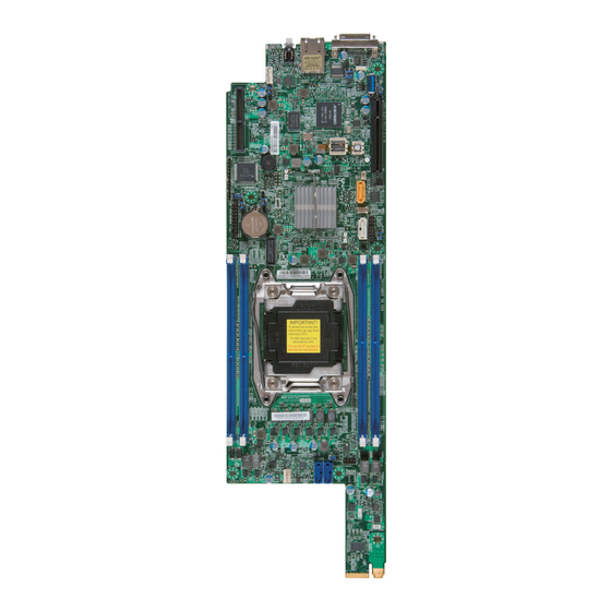
Checklist Congratulations on purchasing your computer motherboard from an acknowledged leader in the industry. Supermicro boards are designed with the utmost attention to detail to provide you with the highest standards in quality and performance. Please check that the following items have all been included with your motherboard. - Page 10 X10SRD-F Motherboard User’s Manual X10SRD-F Motherboard Image Note: All graphics shown in this manual were based upon the latest PCB Revision available at the time of publishing of the manual. The moth- erboard you've received may or may not look exactly the same as the...
-
Page 11: Motherboard Layout
Chapter 1: Introduction Motherboard Layout USB0/1 JUIDB1 JSTBY1 JIPMB1 IPMI_LAN JPG1 JUSB2 USB1(3.0) JPB1 LEDM1 X10SRD-F REV: 1.00 DESIGNED IN USA JSD1 JPF1 JPF2 JBR1 JVRM2 JVRM1 I-SATA5 JWD1 JBT1 I-SATA4 JPME2 JTPM1 S-SGPIO1 FAN1 S-SATA/SAS0 S-SATA/SAS1 Important Notes to the User •... -
Page 12: X10Srd-F Quick Reference
X10SRD-F Motherboard User’s Manual X10SRD-F Quick Reference (not drawn to scale) JUIDB1 JKVM1 IPMI LAN USB0/1 LED2 LED1 USB0/1 JUIDB1 JIPMB1 JSTBY1 JSTBY1 JIPMB1 JPB1 JUSB2 - USB1 IPMI_LAN JI2C1 JPG1 JUSB2 JPG1 USB1(3.0) JI2C2 JPCIE1 JPB1 LEDM1 MICRO LP... -
Page 13: Connectors Description
Chapter 1: Introduction Connectors Description Onboard Battery LGA 2011 Socket for a single Intel ® Xeon™ E5-1600/E5-2600 (v3/v4) series FAN1 System Fan Header IPMI_LAN IPMI Dedicated LAN Port I-SATA4, I-SATA5 SATA 3.0 Ports supported by Intel ® HDD BP Selection JIPMB1 System Management Bus Header for the IPMI Slot JPCIE1... -
Page 14: Motherboard Features
X10SRD-F Motherboard User’s Manual Motherboard Features Intel ® Xeon™ E5-1600/E5-2600 (v3/v4) series (LGA 2011 socket) Note: E5-1600/E5-2600 (v4) requires Revi- sion 2.0 BIOS (or higher). Memory Supports up to 512GB ECC 3DS LRDIMM, 256GB ECC LRDIMM, and 128GB ECC RDIMM at 2400 MHz (max.) memory in four (4) DIMM slots. - Page 15 Chapter 1: Introduction PC Health Monitoring CPU Monitoring Onboard voltage monitors for CPU core, +3.3V, +5V, +12V, +3.3V Stdby, VBAT, Memory and Chipset Tachometer Monitoring CPU Thermal Trip support Thermal Monitor 2 (TM2) support System Management PECI (Platform Environment Configuration Interface) 2.0 support System resource alert via SuperDoctor ®...
- Page 16 X10SRD-F Motherboard User’s Manual X10SRD-F Motherboard Block Diagram CPU0 PROCESSOR Socket 00 QPI0 JPCIE1 QPI1 PCIE 3.0 x16 SATA GEN 3 USB 3.0 PCI-E x1 HEADER R,G,B KVM CONNECTOR DDR 3 RMII AST2400 IPMI LAN FLASH RTL8211E System Block Diagram Note: This is a general block diagram and may not exactly represent the features on your motherboard.
-
Page 17: Chipset Overview
Direct Media Interface (DMI) for chip-to-chip true isochronous communication, providing up to 5 Gb/s of software-transparent data transfer rate on each read/write direction. In addition, the X10SRD-F also features a TCO timer which allows the system to recover from a software/hardware lock and perform tasks, including Function Disable and Intruder Detect. -
Page 18: Special Features
X10SRD-F Motherboard User’s Manual Special Features Recovery from AC Power Loss Basic I/O System (BIOS) provides a setting for you to determine how the system will respond when AC power is lost and then restored to the system. You can choose for the system to remain powered off (in which case you must press the power switch to turn it back on), or for it to automatically return to a power-on state. -
Page 19: System Resource Alert
Chapter 1: Introduction System Resource Alert This feature is available when the system is used with SuperDoctor ® 5 in the Windows OS environment or used with SuperDoctor II in Linux. SuperDoctor is used to notify the user of certain system events. For example, you can also configure SuperDoctor to provide you with warnings when the system temperature, CPU temperatures, voltages and fan speeds go beyond predefined thresholds. - Page 20 X10SRD-F Motherboard User’s Manual Notes 1-12...
-
Page 21: Chapter 2 Installation
The following statements are industry-standard warnings, provided to warn the user of situations which have the potential for bodily injury. Should you have questions or experience difficulty, contact Supermicro's Technical Support department for assis- tance. Only certified technicians should attempt to install or configure components. - Page 22 X10SRD-F Motherboard User's Manual Attention Danger d'explosion si la pile n'est pas remplacée correctement. Ne la remplacer que par une pile de type semblable ou équivalent, recommandée par le fabricant. Jeter les piles usagées conformément aux instructions du fabricant. ¡Advertencia! Existe peligro de explosión si la batería se reemplaza de manera incorrecta.
-
Page 23: Product Disposal
Chapter 2: Installation Product Disposal Warning! Ultimate disposal of this product should be handled according to all national laws and regulations. 製品の廃棄 この製品を廃棄処分する場合、 国の関係する全ての法律 ・ 条例に従い処理する必要が あります。 警告 本产品的废弃处理应根据所有国家的法律和规章进行。 警告 本產品的廢棄處理應根據所有國家的法律和規章進行。 Warnung Die Entsorgung dieses Produkts sollte gemäß allen Bestimmungen und Gesetzen des Landes erfolgen. -
Page 24: Static-Sensitive Devices
X10SRD-F Motherboard User's Manual Static-Sensitive Devices Electrostatic-Discharge (ESD) can damage electronic com ponents. To prevent dam- age to your system board, it is important to handle it very carefully. The following measures are generally sufficient to protect your equipment from ESD. -
Page 25: Motherboard Installation
Pan head screws (7 pieces) (Only if needed) Location of Mounting Holes There are eight (7) mounting holes on the X10SRD-F motherboard. These holes correspond to screw holes in a matching motherboard tray that slides into a blade- type chassis. -
Page 26: Installation Instructions
X10SRD-F Motherboard User's Manual Installation Instructions 1. Locate the mounting holes on the motherboard. Refer to the layout on the previous page for mounting hole locations. 2. Locate the matching mounting holes on the motherboard mounting tray. Install standoffs needed. Align the mounting holes on the motherboard against the mounting holes on the motherboard tray. -
Page 27: Processor And Heatsink Installation
The LGA2011 Socket Currently, there are two kinds of LGA2011 socket mounted on Supermicro moth- erboards, a 'regular' and a 'narrow' sized socket. Though they may look slightly different from one another, the labeling, operation of the hardware, mounting of the CPU are similar on both types. -
Page 28: Opening The Lga2011 Socket
X10SRD-F Motherboard User's Manual Opening the LGA2011 Socket The instructions on the following pages will show the 'regular' type socket. However, they also apply to the 'narrow' type as well. The drawings are provided for illustra- tion purposes only. 1. Before opening the LGA2011 socket, remove the black 'IMPORTANT!' plas- tic protective cap using your fingers and save it for future use. - Page 29 Chapter 2: Installation 3. Press the second load lever labeled 'Close 1st' to release the load plate which covers the CPU socket from its locking position. Press down on Load Lever 'Close 1st' Pull lever away from the socket 4. With the 'Close 1st' lever fully retracted, gently push down on the 'Open 1st' lever to open the load plate.
-
Page 30: Installing The Lga2011 Processor
X10SRD-F Motherboard User's Manual Installing the LGA2011 Processor 1. Use your thumb and index finger to hold the CPU on its edges. Align the CPU keys (semi-circle cutouts) against the socket keys. Socket Keys CPU Keys 2. Once it is aligned, carefully lower the CPU straight down into the socket. (Do not drop the CPU on the socket. - Page 31 Chapter 2: Installation 3. Do not rub the CPU against the surface or against any pins of the socket to avoid damaging the CPU or the socket.) 4. With the CPU inside the socket, inspect the four corners of the CPU to make sure that the CPU is properly installed.
-
Page 32: Installing A Passive Cpu Heatsink
X10SRD-F Motherboard User's Manual Installing a Passive CPU Heatsink 1. Do not apply any thermal grease to the heatsink or the CPU die -- the re- quired amount has already been applied. 2. Place the heatsink on top of the CPU so that the four mounting holes are aligned with those on the Motherboard's and the Heatsink Bracket under- neath. -
Page 33: Removing The Heatsink
Chapter 2: Installation Removing the Heatsink Note: We do not recommend that the CPU or the heatsink be removed. However, if you do need to uninstall the heatsink, please follow the instruc- tions below to uninstall the heatsink to prevent damage done to the CPU or the CPU socket. -
Page 34: System Memory
The X10SRD-F supports up to 512GB ECC 3DS LRDIMM, 256GB ECC LRDIMM, and 128GB ECC RDIMM at 2400 MHz (max.) in four DIMM slots. Check the Supermicro website for a list of memory modules that have been validated for the X10SRD-F motherboard. -
Page 35: Installing And Removing Dimms
Chapter 2: Installation Installing and Removing DIMMs 1. Position the DIMM module's bottom key so that it aligns with the receptive point on the slot. Notches 2. Push a Lock/Release tab Release to the Release position. Make sure that the side notches of the DIMM module aligns with the Lock/Release tab of the... -
Page 36: Memory Population Guidelines
X10SRD-F Motherboard User's Manual Memory Population Guidelines When installing memory modules, the DIMM slots should be populated in the following order: DIMMA1, DIMMB1, DIMMC1 and DIMMD1. • Always use DDR4 DIMM modules of the same size, type and speed. •... -
Page 37: Connectors And I/O Ports
I/O ports. I/O Port Location USB0/1 JUIDB1 JSTBY1 JIPMB1 IPMI_LAN JPG1 JUSB2 USB1(3.0) JPB1 LEDM1 X10SRD-F REV: 1.00 DESIGNED IN USA JSD1 JPF1 JPF2 JBR1 JVRM2 JVRM1 I-SATA5 JWD1 JBT1... -
Page 38: Kvm Port
X10SRD-F Motherboard User's Manual KVM Port The KVM port supports two USB, VGA and UART interface.Please attach a compatible KVM connector/switch to this port. IPMI Port A dedicated IPMI LAN port is located next to the KVM port to provide dedi- cated network connection for IPMI 2.0. -
Page 39: Tpm Header
RSV0 RSV1 SB3V SERIRQ CLKRUN LPCPD RSV2 USB0/1 JUIDB1 JSTBY1 JIPMB1 IPMI_LAN JPG1 JUSB2 USB1(3.0) JPB1 LEDM1 A. TPM Header X10SRD-F REV: 1.00 DESIGNED IN USA JSD1 JPF1 JPF2 JBR1 JVRM2 JVRM1 JWD1 I-SATA5 JBT1 I-SATA4 JPME2 JTPM1 S-SGPIO1 FAN1... -
Page 40: Connecting Cables
X10SRD-F Motherboard User's Manual Connecting Cables This section provides brief descriptions and pin-out definitions for onboard power connectors. Be sure to use the correct cable for each header or connector. Universal Serial Bus (USB) USB Header Pin Definitions One USB 3.0 header (USB1) is located... -
Page 41: Serial Link General Purpose I/O Headers
Refer to the board layout below for the location of the headers. A. S-SGPIO1 USB0/1 JUIDB1 JSTBY1 B. S-SGPIO2 JIPMB1 IPMI_LAN JPG1 JUSB2 USB1(3.0) JPB1 LEDM1 X10SRD-F REV: 1.00 DESIGNED IN USA JSD1 JPF1 JPF2 JBR1 JVRM2 JVRM1 I-SATA5 JWD1 JBT1 I-SATA4... -
Page 42: Internal Buzzer
X10SRD-F Motherboard User's Manual Internal Buzzer Internal Buzzer Pin Definitions The Internal Buzzer, located at SP1, can be Pin# Definitions used to provide audible alarms for various beep Pin 1 Pos. (+) Beep In codes. See the table on the right for pin defini- Pin 2 Neg. -
Page 43: Fan Header
Thermal Management via the IPMI 2.0 interface. See the table on the right for pin definitions. A. Fan Header USB0/1 JUIDB1 JSTBY1 JIPMB1 IPMI_LAN JPG1 JUSB2 USB1(3.0) JPB1 LEDM1 X10SRD-F REV: 1.00 DESIGNED IN USA JSD1 JPF1 JPF2 JBR1 JVRM2 JVRM1 JWD1 I-SATA5 JBT1... -
Page 44: Jumper Settings
X10SRD-F Motherboard User's Manual Jumper Settings Explanation of Jumpers To modify the operation of the motherboard, jumpers can be used to choose between optional settings. Jumpers create shorts between two pins to change the function of the connector. Pin 1 is identified with a square solder pad on the printed circuit board. -
Page 45: Cmos Clear
AC power cord, and then short JBT1 to clear CMOS. A. CMOS Clear USB0/1 JUIDB1 JSTBY1 JIPMB1 IPMI_LAN JPG1 JUSB2 USB1(3.0) JPB1 LEDM1 X10SRD-F REV: 1.00 DESIGNED IN USA JSD1 JPF1 JPF2 JBR1 JVRM2 JVRM1 JWD1 I-SATA5 JBT1... -
Page 46: Vga Enable
X10SRD-F Motherboard User's Manual VGA Enable VGA Enable/Disable Jumper Settings (JPG1) JPG1 allows the user to enable the onboard Pin# Definition VGA connector (through the KVM). Close Pins Enabled (Default) 1-2 to use this function. The default setting is Disabled Enabled. -
Page 47: Manufacturing Mode
USB0/1 JUIDB1 JSTBY1 JIPMB1 IPMI_LAN JPG1 JUSB2 A. ME Manufacturing Mode USB1(3.0) JPB1 B. BIOS Recovery LEDM1 X10SRD-F REV: 1.00 DESIGNED IN USA JSD1 JPF1 JPF2 JBR1 JVRM2 JVRM1 JWD1 I-SATA5 JBT1... -
Page 48: Smb (I 2 C) Bus To Pci Slots
X10SRD-F Motherboard User's Manual SMB (I C) Bus to PCI Slots C to PCI Slots Jumper Settings Jumpers JI C1 and JI C2 allow you to con- Pin# Definition nect the System Management Bus (SMB) to Enabled PCI-E and PCI slots. The default setting is Disabled (Default) set to Disabled. -
Page 49: I 2 C Bus For Vrm
A. JVRM1 B. JVRM2 USB0/1 JUIDB1 JSTBY1 C. JPF1 JIPMB1 IPMI_LAN JPG1 JUSB2 D. JPF2 USB1(3.0) JPB1 LEDM1 X10SRD-F REV: 1.00 DESIGNED IN USA JSD1 JPF1 JPF2 JBR1 JVRM2 JVRM1 JWD1 I-SATA5 JBT1 I-SATA4 JPME2... -
Page 50: Onboard Indicators
X10SRD-F Motherboard User's Manual Onboard Indicators LAN Link/Speed LED Indicator LED Color Definition IPMI Dedicated LAN Port No Connection or 10 Mbps Green (On) 100 Mbps An IPMI Dedicated LAN port installed on the I/O back panel. The yellow LED on... -
Page 51: Unit Id Led
LED Color Definition Red (On) USB0/1 JUIDB1 A. Unit ID LED JSTBY1 JIPMB1 IPMI_LAN B. OVT Indicator JPG1 JUSB2 USB1(3.0) JPB1 LEDM1 X10SRD-F REV: 1.00 DESIGNED IN USA JSD1 JPF1 JPF2 JBR1 JVRM2 JVRM1 JWD1 I-SATA5 JBT1 I-SATA4 JPME2 JTPM1... -
Page 52: Bmc Heartbeat Led
X10SRD-F Motherboard User's Manual BMC Heartbeat LED BMC Heartbeat LED States A BMC Heartbeat LED is located at LEDM1 Color/State Definition on the motherboard. When LEDM1 is blink- Green: BMC: Normal Blinking ing, BMC functions normally. See the table on the right for more information. -
Page 53: 2-10 Serial Ata Connections
A. I-SATA4 B. I-SATA5 USB0/1 JUIDB1 C. SAS0 JSTBY1 JIPMB1 IPMI_LAN D. SAS1 JPG1 JUSB2 USB1(3.0) JPB1 LEDM1 X10SRD-F REV: 1.00 DESIGNED IN USA JSD1 JPF1 JPF2 JBR1 JVRM2 JVRM1 JWD1 I-SATA5 JBT1 I-SATA4 JPME2... - Page 54 X10SRD-F Motherboard User's Manual Notes 2-34...
-
Page 55: Chapter 3 Troubleshooting
Chapter 3: Troubleshooting Chapter 3 Troubleshooting Troubleshooting Procedures Use the following procedures to troubleshoot your system. If you have followed all of the procedures below and still need assistance, refer to the ‘Technical Support Procedures’ and/or ‘Returning Merchandise for Service’ section(s) in this chapter. Always disconnect the AC power cord before adding, changing or installing any hardware components. -
Page 56: Memory Errors
1. Make sure that the DIMM modules are properly installed and fully seated in the slots. 2. You should be using memory recommended by Supermicro (see Section 2-4). Also, it is recommended that you use the memory modules of the same type and speed for all DIMMs in the system. -
Page 57: Technical Support Procedures
Before contacting Technical Support, please make sure that you have followed all the steps listed below. Also, Note that as a motherboard manufacturer, Supermicro does not sell directly to end users, so it is best to first check with your distributor or reseller for troubleshooting services. -
Page 58: Frequently Asked Questions
Answer: It is recommended that you do not upgrade your BIOS if you are not experiencing any problems with your system. Updated BIOS files are located on our website at http://www.supermicro.com/support/bios/. Please check our BIOS warning message and the information on how to update your BIOS on our web site. - Page 59 Chapter 3: Troubleshooting Question: What is the heatsink part number for my X10SRD-F Series motherboard? Answer: For the 1U passive heatsink, ask for SNK-P0047PS. Question: Why can't I recover the BIOS even when I’ve followed the instructions in the user’s manual for the motherboard? Answer: Please disable the IPMI jumper and try it again.
-
Page 60: Battery Removal And Installation
X10SRD-F Motherboard User’s Manual Battery Removal and Installation Battery Removal To remove the onboard battery, follow the steps below: 1. Power off your system and unplug your power cable. 2. Locate the onboard battery as shown below. 3. Using a tool such as a pen or a small screwdriver, push the battery lock out- wards to unlock it. -
Page 61: Returning Merchandise For Service
You can obtain service by calling your vendor for a Returned Merchandise Authorization (RMA) number. For faster service, you may also obtain RMA authorizations online (http://www.supermicro. com/RmaForm/). When you return the motherboard to the manufacturer, the RMA number should be prominently displayed on the outside of the shipping carton, and mailed prepaid or hand-carried. - Page 62 X10SRD-F Motherboard User’s Manual Notes...
-
Page 63: Chapter 4 Bios
BIOS Introduction This chapter describes the AMI BIOS Setup Utility for the X10SRD-F Motherboard. The AMI ROM BIOS is stored in a Flash EEPROM and can be easily updated. This chapter describes the basic navigation of the AMI BIOS Setup Utility setup screens. -
Page 64: Main Setup
Flashing the wrong BIOS can cause irreparable damage to the system. In no event shall Supermicro be liable for direct, indirect, special, incidental, or consequential dam- ages arising from a BIOS update. If you have to update the BIOS, do not shut down or reset the system while the BIOS is updating. - Page 65 Day MM/DD/YY format. The time is entered in HH:MM:SS format. (Note: The time is in the 24-hour format. For example, 5:30 P.M. appears as 17:30:00.) Supermicro X10SRD-F BIOS Version: This item displays the version of the BIOS used in the system.
-
Page 66: Advanced Setup Configurations
X10SRD-F Motherboard User’s Manual Advanced Setup Configurations Use the arrow keys to select Boot Setup and hit <Enter> to access the submenu items: Warning: Take Caution when changing the Advanced settings. An incorrect value, a very high DRAM frequency or incorrect DRAM timing may cause system to become unstable. -
Page 67: Power Configuration
Chapter 4: AMI BIOS Wait For 'F1' If Error This forces the system to wait until the 'F1' key is pressed if an error occurs. The options are Disabled and Enabled. Interrupt 19 Capture Interrupt 19 is the software interrupt that handles the boot disk function. When this item is set to Enabled, the ROM BIOS of the host adaptors will "capture"... -
Page 68: Cpu Configuration
X10SRD-F Motherboard User’s Manual CPU Configuration The following CPU information will be displayed: • Processor Socket • Processor ID • Processor Frequency • Processor Max Ratio • Processor Min Ratio • Microcode Revision • L1 Cache RAM • L2 Cache RAM •... - Page 69 Chapter 4: AMI BIOS PPIN Control Select Unlock/Enable to use the Protected-Processor Inventory Number (PPIN) in the system. The options are Unlock/Enable and Unlock/Disable. Hardware Prefetcher (Available when supported by the CPU) If set to Enabled, the hardware prefetcher will prefetch streams of data and instruc- tions from the main memory to the L2 cache to improve CPU performance.
-
Page 70: Advanced Power Management Configuration
X10SRD-F Motherboard User’s Manual Advanced Power Management Configuration Power Technology Select Energy Efficient to support power-saving mode. Select Custom to custom- ize system power settings. Select Disabled to disable power-saving settings. The options are Disable, Energy Efficient, and Custom. *If the item above is set to "Custom," CPU P State/C State/T State will display:... -
Page 71: Chipset Configuration
Chapter 4: AMI BIOS CPU C State Control Package C State Limit Use this item to set the limit on the C-State package register. The options are C0/1 state, C2 state, C6 (non-Retention) state, and C6 (Retention) state. CPU C3 Report Select Enable to allow the BIOS to report the CPU C3 State (ACPI C2) to the operating system. - Page 72 X10SRD-F Motherboard User’s Manual IIO1 Configuration CPU1 MICRO-LP PCI-E 3.0 X8 SLOT Link Speed Use this item to configure the link speed of a PCI-E port specified by the user. The options are Gen 1 (Generation 1) (2.5 GT/s), Gen 2 (Generation 2) (5 GT/s) and Gen 3 (Generation 3) (8 GT/s).
-
Page 73: Memory Configuration
Chapter 4: AMI BIOS QPI (Quick Path Interconnect) Configuration QPI Status The following information will display: • Number of CPU • Number of IIO COD Enable (Available when the OS and the CPU support this feature) Select Enabled for Cluster-On-Die support to enhance system performance in cloud computing. -
Page 74: Dimm Information
X10SRD-F Motherboard User’s Manual DRAM RAPL (Running Average Power Limit) Baseline Use this feature to set the run-time power-limit baseline for DRAM modules. The options are Disable, DRAM RAPL Mode 0, and DRAM RAPL Mode 1. Set Throttling Mode Throttling improves reliability and reduces power consumption in the proces- sor via automatic voltage control during processor idle states. -
Page 75: South Bridge Configuration
Chapter 4: AMI BIOS Memory Rank Sparing This item indicates if memory rank sparing is supported by the motherboard. Memory rank sparing enhances system memory performance. The options are Enabled and Disabled. Patrol Scrub Patrol Scrubbing is a process that allows the CPU to correct correctable memory errors detected in a memory module and send the correction to the requestor (the original source). -
Page 76: Sata Configuration
X10SRD-F Motherboard User’s Manual XHCI Hand-Off This is a work-around solution for operating systems that do not support XHCI (Extensible Host Controller Interface) hand-off. The XHCI ownership change should be claimed by the XHCI driver. The settings are Enabled and Disabled. - Page 77 Chapter 4: AMI BIOS Configure SATA as Select IDE to configure a SATA drive specified by the user as an IDE drive. Select AHCI to configure a SATA drive specified by the user as an AHCI drive. Select RAID to configure a SATA drive specified by the user as a RAID drive. The options are IDE, AHCI, and RAID.
- Page 78 X10SRD-F Motherboard User’s Manual *If the item above "Configure SATA as" is set to IDE, the following items will display: Serial ATA Port 0~ Port 5 This item indicates that a SATA port specified by the user is not installed or not present.
- Page 79 Chapter 4: AMI BIOS Port 0 ~ Port 5 Spin Up Device On an edge detect from 0 to 1, set this item to allow the PCH to start a COMRESET initialization to the device. The options are Enabled and Disabled. Port 0 ~ Port 5 SATA Device Type Use this item to specify if the SATA port specified by the user should be connected to a Solid State drive or a Hard Disk Drive.
- Page 80 X10SRD-F Motherboard User’s Manual Above 4G Decoding (Available if the system supports 64-bit PCI decoding) Select Enabled to decode a PCI device that supports 64-bit in the space above 4G Address. The options are Enabled and Disabled. SR-IOV Support (Available if the system supports Single-Root Virtualization) Select Enabled for Single-Root IO Virtualization support.
-
Page 81: Super Io Configuration
Chapter 4: AMI BIOS VGA Priority Use this item to select the graphics device to be used as the primary video display at bootup. The options are Onboard and Offboard. Network Stack Select Enabled to enable PXE (Preboot Execution Environment) or UEFI (Unified Extensible Firmware Interface) for network stack support. -
Page 82: Serial Port Console Redirection
X10SRD-F Motherboard User’s Manual Serial Port Console Redirection COM 1 Console Redirection Select Enabled to enable COM Port 1 for Console Redirection, which will allow a client machine to be connected to a host machine at a remote site for networking. - Page 83 Chapter 4: AMI BIOS Flow Control Use this item to set the flow control for Console Redirection to prevent data loss caused by buffer overflow. Send a "Stop" signal to stop sending data when the receiving buffer is full. Send a "Start" signal to start sending data when the receiving buffer is empty.
- Page 84 X10SRD-F Motherboard User’s Manual SOL/COM2 Console Redirection Settings Use this feature to specify how the host computer will exchange data with the client computer, which is the remote computer used by the user. Terminal Type Use this feature to select the target terminal emulation type for Console Redirec- tion.
- Page 85 Chapter 4: AMI BIOS VT-UTF8 Combo Key Support Select Enabled to enable VT-UTF8 Combination Key support for ANSI/VT100 terminals. The options are Enabled and Disabled. Recorder Mode Select Enabled to capture the data displayed on a terminal and send it as text messages to a remote server.
-
Page 86: Acpi Settings
X10SRD-F Motherboard User’s Manual Out-of-Band Management Port The feature selects a serial port in a client server to be used by the Microsoft Windows Emergency Management Services (EMS) to communicate with a re- mote host server. The options are COM1 and COM2/SOL. -
Page 87: Event Logs
Chapter 4: AMI BIOS Event Logs Use this feature to configure Event Log settings. Change SMBIOS Event Log Settings SMBIOS Event Log Change this item to enable or disable all features of the Smbios Event Logging during boot. The options are Enabled and Disabled. Runtime Error Logging Support Change this item to enable or disable runtime error logging. -
Page 88: View Smbios Event Log
X10SRD-F Motherboard User’s Manual When Log is Full Select Erase Immediately to immediately erase all errors in the SMBIOS event log when the event log is full. Select Do Nothing for the system to do nothing when the SMBIOS event log is full. The options are Do Nothing and Erase Immediately. -
Page 89: Ipmi Settings
Chapter 4: AMI BIOS IPMI Settings Use this feature to configure the Intelligent Platform Management Interface(IPMI) settings. IPMI Firmware Revision This item indicates the IPMI firmware revision used in your system. IPMI Status This item indicates the status of the IPMI firmware installed in your system. System Event Log ... -
Page 90: Bmc Network Configuration
X10SRD-F Motherboard User’s Manual Erasing Settings Erase SEL Select Yes, On next reset to erase all system event logs upon next system reboot. Select Yes, On every reset to erase all system event logs upon each system reboot. Select No to keep all system event logs after each system reboot. The options are No, Yes, On next reset, and Yes, On every reset. - Page 91 Chapter 4: AMI BIOS Subnet Mask Subnet masks tell the network which subnet this machine belongs to. The value of each three-digit number separated by dots should not exceed 255. Station MAC Address MAC addresses are 6 two-digit hexadecimal numbers (Base 16, 0 ~ 9, A, B, C, D, E, F) separated by dots (i.e., 00.30.48.D0.D4.60).
-
Page 92: Security
X10SRD-F Motherboard User’s Manual Security This menu allows the user to configure the following security settings for the system. Password Check Select Setup for the system to check for a password at Setup. Select Always for the system to check for a password at bootup or upon entering the BIOS Setup utility. - Page 93 Chapter 4: AMI BIOS Secure Boot Mode Use this item to select the secure boot mode. The options are Standard and Custom. CSM Support Select Enabled to support the EFI Compatibility Support Module (CSM), which provides compatibility support for traditional legacy BIOS for system boot. The op- tions are Enabled and Disabled.
- Page 94 X10SRD-F Motherboard User’s Manual Authorized Signatures This feature allows the user to configure the settings of the authorized signatures. Set New DB Select Yes to load the DB from the manufacturer's defaults. Select No to load the DBT from a file. The options are Yes and No.
-
Page 95: Boot
Chapter 4: AMI BIOS Boot Use this feature to configure Boot Settings: Boot Configuration Setup Prompt Timeout Use this item to indicate the length of time (the number of seconds) for the BIOS to wait before rebooting the system when the setup activation key is pressed. Enter the value of 65535 (0xFFFF) for the BIOS to wait indefinitely. - Page 96 X10SRD-F Motherboard User’s Manual • Dual Boot Order #5 • Dual Boot Order #6 • Dual Boot Order #7 • Dual Boot Order #8 • Dual Boot Order #9 • Dual Boot Order #10 • Dual Boot Order #11 •...
-
Page 97: Save & Exit
Chapter 4: AMI BIOS Save & Exit Select the Exit tab from the BIOS Setup Utility screen to enter the Exit BIOS Setup screen. Discard Changes and Exit Select this option to quit the BIOS Setup without making any permanent changes to the system configuration, and reboot the computer. - Page 98 X10SRD-F Motherboard User’s Manual Restore Optimized Defaults To set this feature, select Restore Defaults from the Exit menu and press <Enter>. These are factory settings designed for maximum system stability, but not for maximum performance. Save As User Defaults To set this feature, select Save as User Defaults from the Exit menu and press <En- ter>.
-
Page 99: Appendix A Bios Error Beep Codes
Appendix A: POST Error Beep Codes Appendix A BIOS Error Beep Codes During the POST (Power-On Self-Test) routines, which are performed each time the system is powered on, errors may occur. Non-fatal errors are those which, in most cases, allow the system to continue with bootup. - Page 100 X10SRD-F Motherboard User’s Manual Notes...
-
Page 101: Appendix B Software Installation Instructions
To install these software programs and drivers, click the icons to the right of these items. (Note: These utility programs are available for download at http:// www.supermicro.com) Driver/Tool Installation Display Screen Note: Click the icons showing a hand writing on the paper to view the readme files for each item. -
Page 102: Installing Superdoctor ® 5
X10SRD-F Motherboard User’s Manual B-2 Installing SuperDoctor ® The Supermicro SuperDoctor ® 5 is a hardware monitoring program that functions in a command-line or web-based interface in Windows and Linux operating systems. The program monitors system health information such as CPU temperature, system voltages, system power consumption, fan speed, and provides alerts via email or Simple Network Management Protocol (SNMP). -
Page 103: Appendix C Uefi Bios Recovery Instructions
Flashing the wrong BIOS can cause irreparable damage to the system. In no event shall Supermicro be liable for direct, indirect, special, incidental, or consequential damages arising from a BIOS update. If you need to update the BIOS, do not shut down or reset the system while the BIOS is updating to avoid possible boot failure. - Page 104 "\" directory of a USB device or a writeable CD/DVD. Note: If you cannot locate the "Super.ROM" file in your driver disk, visit our website at www.supermicro.com to download the BIOS image into a USB flash device and rename it "Super.ROM" for BIOS recovery use.
- Page 105 Appendix C: UEFI BIOS Recovery 4. After locating the new BIOS binary image, the system will enter the BIOS recovery menu as shown below. Note: At this point, you may decide if you want to start with BIOS recovery. If you decide to proceed with BIOS recovery, follow the procedures below. 5.
- Page 106 X10SRD-F Motherboard User’s Manual 6. After the process of BIOS recovery is completed, press any key to reboot the system. 7. Using a different system, extract the BIOS package into a bootable USB flash drive. 8. When a DOS prompt appears, enter FLASH.BAT BIOSname.### at the prompt.
- Page 107 (Disclaimer Continued) The products sold by Supermicro are not intended for and will not be used in life support systems, medical equipment, nuclear facilities or systems, aircraft, aircraft devices, aircraft/emergency com- munication devices or other critical systems whose failure to perform be reasonably expected to result in significant injury or loss of life or catastrophic property damage.
Need help?
Do you have a question about the X10SRD-F and is the answer not in the manual?
Questions and answers