Table of Contents
Advertisement
Quick Links
S
C
UPERMICR
R
• Website: www.supermicro.com
• General Information: marketing@supermicro.com
X10srL-f
• Technical Support: support@supermicro.com
Q
r
g
r
. 1.0a
uICk
eferenCe
uIde
ev
• Phone: +1 (408) 503-8000, Fax: +1 (408) 503-8008
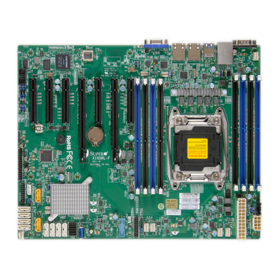
Motherboard Layout and Features
1
9
UID LED - LE1
123
JPL2:LAN2
1
1-2:ENABLE
1 0
BMC
2-3:DISABLE
LEDM1
JPL2
1
1
1
1
1
1
1
5 3
5 2
5 1
5 0
4 9
4 8
4 7
1
1 1
1
1
1 3
1 2
1
1
1 5
1 4
SP1
BT1
1
1
5 4
5 5
1
USB4/5
1 6
1
USB6/7
1 7
1
5 6
USB8/9
JBT1
1
JP3
1 8
1
1 9
JIPMB1
IPMI
X10SRL-F
1
5 7
Rev:
1.01
1
2 0
DESIGNED IN USA
Intel PCH
PWR
ON
RST
PWR
1
I-SATA5
1
FAIL
2 1
JSD2
5 8
OH
FF
NIC
I-SATA9
NIC
1
1
HDD
JSD1
5 9
JSTBY1
PWR
LED
I-SATA8
5V STBY
NMI
T-SGPIO3
1
1
2 2
T-SGPIO2
JOH1
JL1
T-SGPIO1
1
3 0
USB10(3.0)
LE2
JF1
USB11(3.0)
1
2 3
FANA
I-SATA3
I-SATA2
I-SATA1
I-SATA0
1
1
1
1
1
1
1
2 4
2 7
2 9
3 3
2 2
2 8
3 1
1
1
2 5
3 2
1
2 6
= mounting hole
CPU Installation
Heatsink Installation
Screw#4
Socket Keys
Screw#1
CPU Keys
CPU Pin1
Motherboard
Note: Graphics shown in this quick reference guide are for illustration only. Your components may or may not look exactly the same as drawings shown in this
I
ontaCt
nformatIon
1
2
1
1
1
7
1
1
1
1
1
6
5
4
3
8
UID - SW
VGA
COM1
1
4 3
USB2/3(3.0)
USB0/1
FAN5
LAN2
LAN1
IPMI_LAN
1
JPL1:LAN1
4 6
1-2:ENABLE
LAN
2-3:DISABLE
CTRL
1
JPL1
4 4
JVR1
LAN
1
4 5
CTRL
CPU
BAR CODE
IPMI CODE
JPI2C1
BIOS LICENSE
1
JWD1
4 2
2
MAC CODE
1
4 1
JD1:
1-3:
PWR LED
4-7:
SPEAKER
JD1
1
4 0
FAN4
FAN3
1
3 2
FAN2
FAN1
1
1
1
1
1
3 6
3 7
3 8
3 9
3 5
1
3 4
Note: Item numbers are in counterclockwise order.
Front Panel Control (JF1)
Screw#2
20
19
Ground
NMI
X
X
P3V3
Power LED
UID SW
HDD LED
P3V3_STB
NIC1 LED
Screw#3
P3V3_STB
NIC2 LED
UID LED
OH/Fan Fail LED
P3V3
PWR Fail LED
Mounting
Reset
Reset Button
Ground
Holes
Power Button
Ground
PWR
2
1
guide.
f
,
or your system to work ProPerly
/
/
'
drIvers
Images
user
s manual from the lInks below
• Manuals: http://www.supermicro.com/support/manuals
• Drivers & Utilities: ftp://ftp.supermicro.com/CDR_Images/CDR-X10-UP/
• Safety: http://www.supermicro.com/about/policies/safety_information.cfm
Jumpers, Connectors and LED Indicators
Jumpers
Jumper
Item #
Description
JBR1
57
BIOS Recovery
Pins 1-2 (Normal)
JBT1
56
CMOS Clear
Short: Clear CMOS, Open: Normal
JI
C1/JI
C2
13, 12
SMB to PCI-E Slots
Pins 2-3 (Disabled)
2
2
JPB1
14
BMC Enable/Disable
Pins 1-2 (Enabled)
JPG1
15
VGA Enable
Pins 1-2 (Enabled)
JPL1/JPL2
45, 46
LAN1/LAN2 Enable
Pins 1-2 (Enabled)
JPME2
21
Manufacture Mode Select
Pins 1-2 (Normal)
JWD1
41
Watch Dog Enable
Pins 1-2 (Reset)
Connectors
Connector
Item #
Description
Battery (BT1)
55
Onboard Battery
COM1/COM2
1, 11
COM1 (Port)/COM2 (Header)
Fan1 - Fan5, FanA
38,37,36,35,43,23
System/CPU Fan Headers
J24
39
24-pin Main ATX Power Connector
JD1
34
PWR LED/Speaker (Pins 1-3: Power LED, Pins 4-7:
Speaker)
JF1
33
Front Panel Control Header
JIPMB1
19
4-pin External BMC I
C Header (for an IPMI Card)
2
JL1
29
Chassis Intrusion Header
JOH1
28
Overheat/Fan Fail Indicator
JPI
C1
42
Power SMB (System Management Bus)
2
JPWR1
40
8-pin Secondary Power Connector
JSD1/JSD2
59, 58
SATA DOM (Device_On_Module) Power Connector
JSTBY1
32
Standby Power Header
JTPM1
20
Trusted Platform Module/Port 80 Connector
JVR1
44
PWM SMB Programming (for debugging only)
LAN1/LAN2
5, 6
Gigabit (RJ45) Ports (LAN1/2)
IPMI_LAN
3
IPMI_Dedicated LAN
I-SATA 0-9
22
(Intel PCH) Serial ATA (SATA 3.0) Ports 0-9 (6Gb/sec)
(PCH) Slot 1
53
PCI-Express 2.0 (x4 in x8 Slot)
(CPU) Slots 2-7
52, 51, 50
Six (6) PCI-Express 3.0 slots: 2 (x8 in x16), 2 (x8), 1 (x8//
x4), 1 (x0//x4)
49, 48, 47
SP1
54
Internal Speaker/Buzzer
T-SGPIO 1/2/3
26, 25, 24
Serial_Link General Purpose I/O Headers (5V Gen1/Gen2)
UID SW
8
Unit Indentifier Switch
USB 0/1
2
Backpanel USB 2.0 Ports 0/1
USB 2/3
4
Backpanel USB 3.0 Ports 2/3
USB 4/5, 6/7, 8/9
16, 17, 18
Front Panel Accessible USB 2.0 Headers 4/5, 6/7, 8/9
USB 10, 11 (3.0)
27, 31
Front Panel Accessible USB 3.0 Ports 10, 11
VGA
7
Backpanel VGA Port
LED Indicators
LED
Item #
Description
State/Color
LE1
9
UID LED
Blue: On
LE2
30
Onbaord PWR LED
Green: On
LEDM1
10
BMC Heartbeat LED
Green: Blinking
Note: Refer to Chapter 1 of the User Manual for detailed information on jumpers, connectors,
and LED indicators.
P
Please download aPProPrIate
aCkage
:
• One (1) Supermicro Motherboard
• Ten (10) SATA Cables
Memory Support
The X10SRL-F supports eight ECC DDR4 RDIMM/LRDIMM at 2400 MHz
Default
(max.) memory (1 DPC) up to 256GB RDIMM or 512GB LRDIMM. Populat-
ing these DIMM modules with a pair of memory modules of the same type
and same size will result in interleaved memory, which will improve memory
performance.
Populating RDIMM/LRDIMM DDR4
Memory Modules for the E5-2600v3-
based Motherboard
Speed (MT/s); Voltage
(V);
Slot Per Channel (SPC)
and DIMM Per Channel
DIMM Capacity
(DPC)
Ranks Per
DIMM and
(GB)
Type
1 Slot Per
Data
2 Slots Per Channel
Channel
Width
1DPC
1DPC
4Gb
8Gb
1.2V
1.2V
RDIMM
SRx4
8GB
16GB
2133
2133
RDIMM
SRx8
4GB
8GB
2133
2133
RDIMM
DRx8
8GB
16GB
2133
2133
2133
2133
RDIMM
DRx4
16GB
32GB
LRDIMM
QRx4
32GB
64GB
2133
2133
LRDIMM
8Rx4
64GB
128GB
2133
2133
†
3DS
DIMM Memory Installation
Insert the desired number of DIMMs into the memory slots, starting with
DIMMA1 (Channel A, Slot 1).
Receptive Point
Release Tabs
Back Panel I/O Connectors
B
E
Status
Unit Identified
A
C
F
System Power On
D
BMC Normal
Note: Refer to Chapter 2 of the User Manual for detailed information on memory support and CPU/
motherboard installation instructions.
C
ontents
Populating RDIMM/LRDIMM DDR4
Memory Modules for the E5-2600v4-
based Motherboard
Speed (MT/s); Voltage (V);
Slot Per Channel (SPC) and DIMM Per
Channel (DPC)
Ranks Per
DIMM Capacity
1 Slot Per
DIMM and
(GB)
2 Slots Per Channel
Type
Channel
Data
Width
1DPC
1DPC
2DPC
4Gb
8Gb
1.2V
1.2V
1.2V
2DPC
RDIMM
SRx4
8GB
16GB
2400
2400
2133
1.2V
RDIMM
SRx8
4GB
8GB
2400
2400
2133
1866
RDIMM
DRx8
8GB
16GB
2400
2400
2133
1866
RDIMM
DRx4
16GB
32GB
2400
2400
2133
1866
2400
2400
2400
LRDIMM
QRx4
32GB
64GB
1866
LRDIMM
8Rx4
64GB
128GB
2400
2400
2400
3DS
2133
2133
Notches
Press both notches
straight down into
the memory slot.
Backplane I/O Panel
A. COM1
F. USB Port 4 (3.0)
B. IPMI LAN
G. LAN1
C. USB Port 0 (2.0)
H. LAN2
D. USB Port 1 (2.0)
I. VGA Port
E. USB Port 3 (3.0)
J. UID Switch
G
H
I
J
Advertisement
Table of Contents


Need help?
Do you have a question about the X10SRL-F and is the answer not in the manual?
Questions and answers