Table of Contents
Advertisement
Quick Links
Advertisement
Table of Contents

Related Manuals for Supermicro X10SDV


Summary of Contents for Supermicro X10SDV
- Page 1 X10SDV Flex ATX Series USER’S MANUAL 1.0a...
- Page 2 This product, including software and docu- mentation, is the property of Supermicro and/or its licensors, and is supplied only under a license. Any use or reproduction of this product is not allowed, except as expressly permitted by the terms of said license.
-
Page 3: About This Motherboard
10 Gigabit Ethernet SFP+ ports, up to 6 Gigabit Intel Ethernet ports, USB 3.0 and a thermal design up to 65 watts. The X10SDV Flex ATX Series motherboard provides software consistency from the data center to the storage and network edge with the same instruction set as the robust Xeon processor. -
Page 4: Conventions Used In The Manual
X10SDV Flex ATX Series Motherboard User’s Manual Conventions Used in the Manual: Special attention should be given to the following symbols for proper installation and to prevent damage done to the components or injury to yourself: Warning: Critical information to prevent damage to the components or injury to your- self. -
Page 5: Contacting Supermicro
Super Micro Computer, Inc. 980 Rock Ave. San Jose, CA 95131 U.S.A. Tel: +1 (408) 503-8000 Fax: +1 (408) 503-8008 Email: marketing@supermicro.com (General Information) support@supermicro.com (Technical Support) Web Site: www.supermicro.com Europe Address: Super Micro Computer B.V. Het Sterrenbeeld 28, 5215 ML... -
Page 6: Table Of Contents
X10SDV Flex ATX Series Motherboard User’s Manual Table of Contents Preface Chapter 1 Introduction Overview ......................1-1 Processor Overview ..................1-15 Special Features ................... 1-16 PC Health Monitoring ..................1-16 ACPI Features ....................1-17 Power Supply ....................1-17 Chapter 2 Installation Standardized Warning Statements .............. - Page 7 Table of Contents NIC1/NIC2 (LAN1/LAN2) ................2-16 Overheat (OH)/Fan Fail/PWR Fail/UID LED ..........2-17 Reset Button ................... 2-17 Power Fail LED ..................2-18 Connecting Cables ..................2-19 ATX PWR, DC PWR and HDD PWR Connectors (JPW1, JPV1, JPH1) 2-19 Fan Headers (FAN1 ~ FAN4, FANA, FANB)..........2-20 Chassis Intrusion ..................
- Page 8 X10SDV Flex ATX Series Motherboard User’s Manual 10G LAN Activity LED ................2-37 10G LAN Link Status LED ............... 2-37 SAS Hearbeat LED .................. 2-38 SATA Connections ..................2-39 SATA Ports ....................2-39 SAS Ports (7TP8F/7TP4F only) ............... 2-39 M.2 Socket ....................2-40 Mini PCI-E Slot ..................
-
Page 9: Chapter 1 Introduction
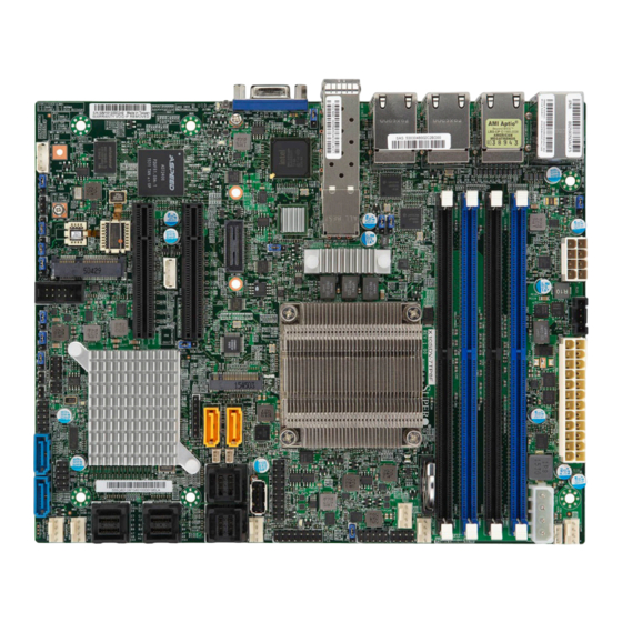
Checklist Congratulations on purchasing your computer motherboard from an acknowledged leader in the industry. Supermicro boards are designed with the utmost attention to detail to provide you with the highest standards in quality and performance. Please check that the following items have all been included with your motherboard. - Page 10 X10SDV Flex ATX Series Motherboard User’s Manual X10SDV-7TP8F Motherboard Image Note: All graphics shown in this manual were based upon the latest PCB Revision available at the time of publishing of the manual. The motherboard you have re- ceived may or may not look exactly the same as the graphics shown in this manual.
- Page 11 Chapter 1: Introduction X10SDV-7TP4F Motherboard Image X10SDV-4C-7TP4F Motherboard Image X10SDV-2C-7TP4F Motherboard Image Note: All graphics shown in this manual were based upon the latest PCB Revision available at the time of publishing of the manual. The motherboard you have re-...
- Page 12 X10SDV Flex ATX Series Motherboard User’s Manual X10SDV-TP8F Motherboard Image X10SDV-2C-TP8F Motherboard Image Note: All graphics shown in this manual were based upon the latest PCB Revision available at the time of publishing of the manual. The motherboard you have re-...
- Page 13 Chapter 1: Introduction X10SDV-2C-TP4F Motherboard Image Note: All graphics shown in this manual were based upon the latest PCB Revision available at the time of publishing of the manual. The motherboard you have re- ceived may or may not look exactly the same as the graphics shown in this manual.
- Page 14 X10SDV Flex ATX Series Motherboard User’s Manual X10SDV-4C+-TP4F Motherboard Image Note: All graphics shown in this manual were based upon the latest PCB Revision available at the time of publishing of the manual. The motherboard you have re- ceived may or may not look exactly the same as the graphics shown in this manual.
- Page 15 Chapter 1: Introduction X10SDV Flex ATX Series Motherboard Layout LED7 JI2C1/JI2C2: JBR1 PRESS FIT 1-2:ENABLE 1-2:NORMAL BAR CODE 2-3:DISABLE 2-3:BIOS RECOVERY JPG1: 1-2:ENABLE 2-3:DISABLE JPS1:SAS 1-2:ENABLE JPL3: 2-3:DISABLE LAN3/4/5/6 M2_SRW3 1-2:ENABLE JWD1:WATCH DOG 2-3:DISABLE 1-2:RST 2-3:NMI JL1: CHASSIS INTRUSION JOH1-OH...
- Page 16 X10SDV Flex ATX Series Motherboard User’s Manual X10SDV Flex ATX Series Motherboard Quick Reference LAN7/8 JPL3 LAN5/6 LED8 IPMI LAN LAN3/4 LEDM1 LED7 USB0/1 MP-SRW1 LAN1/2 MP-SRW2 LED7 JI2C1/JI2C2: JBR1 1-2:ENABLE PRESS FIT 1-2:NORMAL BAR CODE 2-3:DISABLE 2-3:BIOS RECOVERY JPG1:...
- Page 17 Chapter 1: Introduction X10SDV Flex ATX Series Motherboard Model Variation Tables X10SDV Flex ATX Series Motherboard Model Variation Table Model X10SDV- X10SDV- X10SDV-4C- X10SDV-2C- 7TP8F 7TP4F 7TP4F 7TP4F Processor Name Xeon D-1587 Xeon D-1537 Xeon D-1518 Pentium D1508 # of Cores...
- Page 18 X10SDV Flex ATX Series Motherboard User’s Manual Jumpers Jumper Description Default JBR1 BIOS Recovery Pins 1-2 (Normal) JBT1 CMOS Clear Open: Normal, Short: Clear CMOS C1/JI SMB to PCI-Exp. Slots Pins 2-3 (Disabled) JPB1 BMC Enable (Debug use only) Pins 1-2 (Enabled)
- Page 19 Chapter 1: Introduction JOH1 Overheat LED Header JPH1 4-pin Power Connector for HDD use (To provide power from the motherboard to onboard HDD devices.) Power Supply SMBus I C Header JPV1 12V 8-pin DC Power Connector (To provide alternative power for special enclosure when the 24-pin ATX power is not in use.) JPW1 24-pin ATX Power Connector...
-
Page 20: Motherboard Features
X10SDV Flex ATX Series Motherboard User’s Manual Motherboard Features Intel Xeon/Pentium D-1500 Family Processor (BGA) Memory Supports up to 128GB DDR4 ECC RDIMM or 64GB DDR4 ECC/Non-ECC UDIMM with a max data rate of 2133MHz in four (4) slots DIMM sizes... - Page 21 Chapter 1: Introduction BIOS 128 Mb AMI BIOS ® SPI EEPROM BIOS Plug and Play, ACPI 5.0, SMBIOS 2.8, BIOS Rescue Hot-Key, RTC Wakeup, Dual-Boot Block Power Configuration ACPI/ACPM Power Management (S0, S4 and S5 only) Wake-On LAN Power Button Override Power-on mode for AC power recovery PC Health Monitoring Onboard Voltage Monitoring...
-
Page 22: System Block Diagram
X10SDV Flex ATX Series Motherboard User’s Manual X10SDV Flex ATX Series Block Diagram DDR4 1600/1866/2133 PCIE 3.0 x8 JPCIE1 PCIE 3.0 x8 PCIE 3.0 x8 JPCIE2 PCIE 3.0 x8 MINI-SAS HD PROCESSOR PCIE 3.0 x4 SAS2 LSI SAS2116 PCIE 3.0 x4 M.2 CONN... -
Page 23: Processor Overview
Chapter 1: Introduction Processor Overview The Intel ® Xeon D-1500 Series processor is a low-powered 64-bit SoC (System-on- a-Chip) processor that is optimized to deliver high performance, energy efficiency, and enhances the total cost of ownership solutions. The low-power consumption of the processor makes it suitable for microservers that can effectively take on hyperscale workloads, intelligent edge network or ultra-dense embedded devices. -
Page 24: Special Features
Environmental Temperature Control The X10SDV Flex ATX Series motherboard comes with a passive or active heatsink built in. Please follow the instructions given in your system design guide or your system user manual to provide adequate airflow to your system. The onboard Base- Board Management Controller (BMC) monitors CPU, memory and motherboard environment temperatures for fan control and PC health management. -
Page 25: Acpi Features
Windows ® 7, Windows 8, and Windows 2008 operating systems. The X10SDV series motherboards support S0, S4 and S5 only. Power Supply As with all computer products, a stable power source is necessary for proper and reliable operation. - Page 26 X10SDV Flex ATX Series Motherboard User’s Manual Notes 1-18...
-
Page 27: Chapter 2 Installation
The following statements are industry-standard warnings, provided to warn the user of situations which have the potential for bodily injury. Should you have questions or experience difficulty, contact Supermicro's Technical Support department for assis- tance. Only certified technicians should attempt to install or configure components. - Page 28 X10SDV Flex ATX Series Motherboard User’s Manual Attention Danger d'explosion si la pile n'est pas remplacée correctement. Ne la remplacer que par une pile de type semblable ou équivalent, recommandée par le fabricant. Jeter les piles usagées conformément aux instructions du fabricant.
-
Page 29: Product Disposal
Chapter 2: Installation Product Disposal Warning! Ultimate disposal of this product should be handled according to all national laws and regulations. 製品の廃棄 この製品を廃棄処分する場合、 国の関係する全ての法律 ・ 条例に従い処理する必要が あり ます。 警告 本产品的废弃处理应根据所有国家的法律和规章进行。 警告 本產品的廢棄處理應根據所有國家的法律和規章進行。 Warnung Die Entsorgung dieses Produkts sollte gemäß allen Bestimmungen und Gesetzen des Landes erfolgen. -
Page 30: Static-Sensitive Devices
X10SDV Flex ATX Series Motherboard User’s Manual القىانين واللىائح الىطنية جميع وفقا ل ينبغي التعامل معه هذا المنتج من التخلص النهائي عند 경고! 이 제품은 해당 국가의 관련 법규 및 규정에 따라 폐기되어야 합니다. Waarschuwing De uiteindelijke verwijdering van dit product dient te geschieden in overeenstemming met alle nationale wetten en reglementen. -
Page 31: Motherboard Installation
Chapter 2: Installation Motherboard Installation All motherboards have standard mounting holes to fit different types of chassis. Make sure that the locations of all the mounting holes for both motherboard and chassis match. Although a chassis may have both plastic and metal mounting fas- teners, metal ones are highly recommended because they ground the motherboard to the chassis. -
Page 32: Installing The Motherboard
X10SDV Flex ATX Series Motherboard User’s Manual Installing the Motherboard 1. Install the I/O shield into the back of the chassis. 2. Locate the mounting holes on the motherboard. See the previous page. 3. Locate the matching mounting holes on the chassis. Align the mounting holes on the motherboard against the mounting holes on the chassis. -
Page 33: Memory Support
Chapter 2: Installation Memory Support The X10SDV Flex ATX Series motherboard supports up to 128GB of DDR4 ECC RDIMM or 64GB of DDR4 ECC/Non-ECC UDIMM with speeds up to 2133MHz in four memory slots. Populating these DIMM slots with memory modules of the same type and size will result in interleaved memory, which will improve memory performance. -
Page 34: Memory Installation Guidelines
X10SDV Flex ATX Series Motherboard User’s Manual Memory Installation Guidelines When installing memory modules, the DIMM slots should be populated in the following order: DIMMA1, DIMMB1, then DIMMA2, DIMMB2. • Always use DDR4 DIMM modules of the same size, type and speed. Mixing memory modules of different types and speeds is not allowed. -
Page 35: Connectors/Io Ports
Chapter 2: Installation Connectors/IO Ports The I/O ports are color coded in conformance with the industry standards. See the figure below for the colors and locations of the various I/O ports. Back panel I/O Panel LED7 JI2C1/JI2C2: JBR1 1-2:ENABLE 1-2:NORMAL PRESS FIT BAR CODE 2-3:DISABLE... -
Page 36: Serial Port
X10SDV Flex ATX Series Motherboard User’s Manual Serial Port COM Port 1 Pin Definitions A COM port is on the motherboard to Pin # Definition Pin # Definition provide a front accessible serial con- nection. See the table on the right for pin definitions. -
Page 37: Gigabit Ethernet Lan Ports
Chapter 2: Installation Gigabit Ethernet LAN Ports LAN Port Pin Definitions Up to six Gigabit Ethernet ports (LAN1 Pin # Definition Pin # Definition ~ LAN6, LAN3 ~ LAN6 on 7TP8F/TP8F SGND only) and an IPMI LAN port are located TD0+ Act LED on the I/O back panel to provide net-... -
Page 38: Universal Serial Bus (Usb)
X10SDV Flex ATX Series Motherboard User’s Manual Universal Serial Bus (USB) Two USB 3.0 ports (USB0/1) are located on the I/O back plane. Two USB 2.0 head- ers (USB3/4 and USB5/6) and one USB Type-A header are on the motherboard to provide front panel access. -
Page 39: Unit Identifier Switch
Note: UID can also be triggered via IPMI on the motherboard. For more information on IPMI, please refer to the IPMI User's Guide posted on our website at http://www.supermicro. com. A. UID Switch B. Rear UID LED LED7... -
Page 40: Front Control Panel
These connectors are designed spe- cifically for use with Supermicro chassis. See the figure below for the descriptions of the front control panel buttons and LED indicators. Refer to the following section for descriptions and pin definitions. -
Page 41: Front Control Panel Pin Definitions
Chapter 2: Installation Front Control Panel Pin Definitions Power LED Power LED Pin Definitions (JF1) The Power LED connection is located Pin# Definition on pins 15 and 16 of JF1. Refer to the 3.3V table on the right for pin definitions. PWR LED Power Button Power Button... -
Page 42: Hdd Led
X10SDV Flex ATX Series Motherboard User’s Manual HDD LED HDD LED Pin Definitions (JF1) The HDD LED connection is located Pin# Definition on pins 13 and 14 of JF1. Attach a 3.3V Standby cable here to indicate the status of... -
Page 43: Overheat (Oh)/Fan Fail/Pwr Fail/Uid Led
Chapter 2: Installation Overheat (OH)/Fan Fail/PWR Fail/ OH/Fan Fail/PWR Fail/Blue UID LED UID LED Pin Definitions (JF1) Pin# Definition Connect an LED cable to pins 7 and Blue UID LED 8 of Front Control Panel to use the OH/Fan Fail/Power Fail Cathode Overheat/Fan Fail/Power Fail and UID LED connections. -
Page 44: Power Fail Led
X10SDV Flex ATX Series Motherboard User’s Manual Power Fail LED Power Fail Pin Definitions (JF1) The Power Fail LED connection is lo- Pin# Definition cated on pins 5 and 6. Refer to the table 3.3V on the right for pin definitions. -
Page 45: Connecting Cables
Chapter 2: Installation Connecting Cables This section provides brief descriptions and pin-out definitions for onboard headers and connectors. Be sure to use the correct cable for each header or connector. ATX PWR, DC PWR and HDD PWR ATX Power 24-pin Connector Connectors (JPW1, JPV1, JPH1) Pin Definitions (JPW1) Pin#... -
Page 46: Fan Headers (Fan1 ~ Fan4, Fana, Fanb)
X10SDV Flex ATX Series Motherboard User’s Manual Fan Headers (FAN1 ~ FAN4, FANA, FANB) Fan Header Pin Definitions This motherboard has six 4-pin fan headers. Pin# Definition Although pins 1-3 of the fan headers are back- Ground (Black) ward compatible with the traditional 3-pin fans,... -
Page 47: 4-Pin External I
Chapter 2: Installation 4-pin External I C BMC Header External I C Header Pin Definitions A System Management Bus header Pin# Definition for IPMI 2.0 is located at JIPMB1. Data Connect the appropriate cable here Ground to use the IPMI I C connection on Clock your system. -
Page 48: Tpm Header/Port 80 Header
X10SDV Flex ATX Series Motherboard User’s Manual TPM Header/Port 80 Header TPM/Port 80 Header Pin Definitions A Trusted Platform Module/Port 80 Pin # Definition Pin # Definition header, located at JTPM1, provides LCLK Trusted Platform (TPM) support and LFRAME# <(KEY)>... -
Page 49: Speaker
Chapter 2: Installation Speaker Speaker Connector Pin Definitions On the JD1 header, pins 1-3 are used Pin# Definition for the Power LED and pins 4-7 are Power LED used for the speaker. See the table on Speaker the right for pin definitions. Standby Power Standby Power Pin Definitions... -
Page 50: Serial Link I/O Header
X10SDV Flex ATX Series Motherboard User’s Manual Serial Link I/O Header Serial Link I/O Header Pin Definitions The Serial Link General Purpose In- Pin# Definition Definition put/Output (SGPIO) header is used to communicate with the enclosure man- Ground DATA Out agement chip in the system. -
Page 51: Nvme I 2 C Header
Chapter 2: Installation NVMe I C Header Connector JNVI C is a management header for the Supermicro AOC NVMe PCI-E peripheral cards. Please connect the I C cable to this connector. Power SMB (I C) Header Standby Power Pin Definitions... -
Page 52: General Purpose I/O Header
X10SDV Flex ATX Series Motherboard User’s Manual General Purpose I/O Header GPIO Header Pin Definitions The JGP1 header is a general purpose Pin# Definition Definition I/O on a pin header. See the table on P3V3 the right for pin definitions. Refer to the board layout below for the location of the header. -
Page 53: Jumper Settings
Chapter 2: Installation Jumper Settings Explanation of Jumpers To modify the operation of the mother- board, jumpers can be used to choose between optional settings. Jumpers create shorts between two pins to change the function of the connector. Pin 1 is identified with a square solder pad on the printed circuit board. -
Page 54: Cmos Clear
X10SDV Flex ATX Series Motherboard User’s Manual CMOS Clear JBT1 is used to clear CMOS. Instead of pins, this "jumper" consists of contact pads to prevent accidental clearing of CMOS. To clear CMOS, use a metal object such as a small screwdriver to touch both pads at the same time to short the connec- tion. -
Page 55: Watch Dog Timer Enable
Chapter 2: Installation Watch Dog Timer Enable Watch Dog Jumper Settings Watch Dog (JWD1) is a system monitor that Pin# Definition can be used to enter LAN bypass default set- Reset (Default) tings, reset the system or enter NMI when the Timer expires. -
Page 56: Management Engine (Me) Recovery
X10SDV Flex ATX Series Motherboard User’s Manual Management Engine (ME) Recovery ME Recovery Jumper Settings Use JPME1 to select ME Firmware Re- Pin# Definition covery mode, which will limit resource Normal (Default) allocation for essential system operation ME Recovery only in order to maintain normal power operation and management. -
Page 57: Bios Recovery
Chapter 2: Installation BIOS Recovery BIOS Recovery Jumper Settings Close pins 2 and 3 of jumper JBR1 for Pin# Definition BIOS recovery. The default setting is on Normal pins 1 and 2 for normal operation. See BIOS Recovery the table on the right for jumper settings. BMC Enabled BMC Enabled JPB1 allows you to enable the BMC... -
Page 58: Gbe Lan Ports Enable/Disable
LAN ports 1 and 2, respectively. Enabled (Default) Use JPL3 to enable or disable LAN ports 3, Disabled 4, 5, and 6. JPL3 is available on X10SDV- 7TP8F/TP8F only. See the table on the right for jumper settings. The default setting is enabled. -
Page 59: Sas Port Enable/Disable
Chapter 2: Installation SAS Port Enable/Disable SAS Port Enable/Disable Jumper Settings Use JPS1 to enable the onboard SAS ports. Pin# Definition See the table on the right for jumper settings. Enabled Disabled A. SAS Port Enable LED7 JI2C1/JI2C2: JBR1 1-2:ENABLE 1-2:NORMAL PRESS FIT BAR CODE... -
Page 60: Onboard Indicators
X10SDV Flex ATX Series Motherboard User’s Manual Onboard Indicators Overheat/PWR Fail/Fan Fail LAN LEDs LED Settings The Ethernet ports have two LEDs. On Color Status Definition each port, one LED indicates activity No Connection when flashing while the other LED may be... -
Page 61: Onboard Power Led
Chapter 2: Installation Onboard Power LED Onboard PWR LED Indicator LED Settings An onboard Power LED is located at Color Definition LED3 on the motherboard. When this System Off (PWR cable LED is on, the system is on. Be sure to not connected) turn off the system and unplug the power Green... -
Page 62: Unit Identification Led
X10SDV Flex ATX Series Motherboard User’s Manual Unit Identification LED UID LED Status A rear UID LED indicator (LED7) is located Color/State Status next to the Unit Identifier (UID) switch on the Blue: On Unit Identified I/O back panel. The front panel UID LED is located at pin 7 of the Front Control Panel at JF1. -
Page 63: 10G Lan Activity Led
Chapter 2: Installation 10G LAN Activity LED 10G LAN Activity LED Indicator The 10G LAN Activity LED for LAN7 is Color/State Definition located at LEDT2, and the 10G LAN LED LEDT2 LAN7 Active Activity LED for LAN8 is located at LEDT4. Green: Blinking When the LEDs are blinking, LAN7/LAN8 LEDT4... -
Page 64: Sas Hearbeat Led
X10SDV Flex ATX Series Motherboard User’s Manual SAS Hearbeat LED SAS Hearbeat LED Indicator A SAS heartbeat LED is located at LEDS1. Color Definition When LEDS1 flashes, it indicates activity Green: SAS Active on a SAS port. See the table on the right Blinking for more information. -
Page 65: Sata Connections
SATA Ports This motherboard has six SATA 3.0 ports. I-SATA0 and I-SATA1 have built-in power pins to support Supermicro's SATA DOM (Disk On Module) solutions. I-SATA4 is via the JMD1 M.2 connector, I-SATA5 is via the JMP1 Mini PCI-E slot. -
Page 66: M.2 Socket
The X10SDV series deploys an M key only dedicated for SSD devices with the ultimate performance capability in a PCI Express 3.0 X4 interface for native PCIe SSD support. The X10SDV M.2 is mux with the I-SATA4 port for legacy SATA SSD devices. -
Page 67: Chapter 3 Troubleshooting
Chapter 3: Troubleshooting Chapter 3 Troubleshooting Troubleshooting Procedures Use the following procedures to troubleshoot your system. If you have followed all of the procedures below and still need assistance, refer to the ‘Technical Support Procedures’ and/or ‘Returning Merchandise for Service’ section(s) in this chapter. Always disconnect the AC power cord before adding, changing or installing any hardware components. -
Page 68: Memory Errors
2. You should be using either DDR4 ECC RDIMM or ECC/Non-ECC UDIMM up to 2133MHz memory recommended by Supermicro. Also, it is required that you use the memory modules of the same type and speed for all DIMMs in the system. -
Page 69: Technical Support Procedures
Before contacting Technical Support, please make sure that you have followed all the steps listed below. Also, Note that as a motherboard manufacturer, Supermicro does not sell directly to end users, so it is best to first check with your distributor or reseller for troubleshooting services. -
Page 70: Frequently Asked Questions
Frequently Asked Questions Question: What type of memory does my motherboard support? Answer: The X10SDV Flex ATX Series motherboard supports up to 128GB of DDR4 ECC RDIMM or 64GB of DDR4 ECC/Non-ECC UDIMM memory of speeds up to 2133MHz. See Section 2-4 for details on installing memory. -
Page 71: Battery Removal And Installation
Chapter 3: Troubleshooting Battery Removal and Installation Battery Removal To remove the onboard battery, follow the steps below: 1. Power off your system and unplug your power cable. 2. Locate the onboard battery as shown below. 3. Using a tool such as a pen or a small screwdriver, push the battery lock out- wards to unlock it. -
Page 72: Returning Merchandise For Service
You can obtain service by calling your vendor for a Returned Merchandise Authorization (RMA) number. For faster service, you may also obtain RMA authorizations online (http://www.supermicro. com/RmaForm/). When you return the motherboard to the manufacturer, the RMA number should be prominently displayed on the outside of the shipping carton, and mailed prepaid or hand-carried. -
Page 73: Chapter 4 Bios
When an option is selected in the left frame, it is highlighted in white. Often a text message will accompany it. (Note: the AMI BIOS has default text messages built in. Supermicro retains the option to include, omit, or change any of these text messages.) The AMI BIOS setup utility uses a key-based navigation system called "hot keys". -
Page 74: How To Start The Setup Utility
Flashing the wrong BIOS can cause irreparable damage to the system. In no event shall Supermicro be liable for direct, indirect, special, incidental, or consequential dam- ages arising from a BIOS update. If you have to update the BIOS, do not shut down or reset the system while the BIOS is updating. - Page 75 Day MM/DD/YY format. The time is entered in HH:MM:SS format. Note: The time is in the 24-hour format. For example, 5:30 P.M. appears as 17:30:00. The following BIOS items will also be displayed: Supermicro X10SDV-7TP8F Version Build Date Memory Information Total Memory This displays the total size of memory available in the system.
-
Page 76: Advanced Setup Configurations
X10SDV Flex ATX Series Motherboard User’s Manual Advanced Setup Configurations Use the arrow keys to select Boot Setup and press <Enter> to access the submenu items. Warning: Take caution when changing the Advanced settings. An incorrect value, a very high DRAM frequency, or an incorrect DRAM timing setting may make the system unstable. -
Page 77: Power Configuration
Chapter 4: AMI BIOS Wait For 'F1' If Error Use this feature to force the system to wait until the 'F1' key is pressed if an error occurs. The options are Disabled and Enabled. INT19 (Interrupt 19) Trap Response Interrupt 19 is the software interrupt that handles the boot disk function. When this item is set to Immediate, the ROM BIOS of the host adaptors will "capture"... -
Page 78: Cpu Configuration
X10SDV Flex ATX Series Motherboard User’s Manual CPU Configuration The following CPU information will be displayed: • Processor ID • Processor Frequency • Processor Max Ratio • Processor Min Ratio • Microcode Revision • L1 Cache RAM • L2 Cache RAM •... - Page 79 Chapter 4: AMI BIOS Execute Disable Bit (Available if supported by the OS & the CPU) Select Enabled to enable the Execute-Disable Bit which will allow the processor to designate areas in the system memory where an application code can execute and where it cannot, thus preventing a worm or a virus from flooding illegal codes to overwhelm the processor or damage the system during an attack.
-
Page 80: Advanced Power Management Configuration
X10SDV Flex ATX Series Motherboard User’s Manual Note: If a change is made to this setting, you will need to reboot the system for the change to take effect. Refer to Intel’s website for detailed information. Advanced Power Management Configuration This section is used to configure the following CPU Power Management settings. - Page 81 Chapter 4: AMI BIOS CPU HWPM State Control Enable CPU HWPM Select Enable for better CPU energy performance. The options are Disable, HWPM NATIVE MODE, and HWPM OOB MODE. Enable CPU Autonomous Cstate Use this feature to enable CPU Autonomous C State, which converts HALT instructions to Mwait.
- Page 82 X10SDV Flex ATX Series Motherboard User’s Manual CPU T State Control ACPI (Advanced Configuration Power Interface) T-States Select Enable to support CPU throttling by the operating system to reduce power consumption. The options are Disable and Enable. CPU Advanced PM Turning ...
-
Page 83: Chipset Configuration
Chapter 4: AMI BIOS Energy Efficient Turbo Use this feature to enable energy efficient turbo mode. The options are En- able and Disable. DRAM RAPL Configuration Override BW_LIMIT_TF This feature allows the user to turn off the "Override BW_LIMIT_TF (Time Frame)"... - Page 84 X10SDV Flex ATX Series Motherboard User’s Manual CPU SLOT 6 PCI-E 3.0 X8 This item configures the link speed of the PCI-E port specified by the user. The options are Gen 1 (Generation 1) (2.5 GT/s), Gen 2 (Generation 2) (5 GT/s), and Gen 3 (Generation 3) (8 GT/s).
-
Page 85: Memory Configuration
Chapter 4: AMI BIOS Memory Configuration Enforce POR Select Enable to enforce POR restrictions on DDR4 frequency and voltage programming. The options are Enabled and Disabled. Memory Frequency Use this feature to set the maximum memory frequency for onboard memory modules. -
Page 86: South Bridge
X10SDV Flex ATX Series Motherboard User’s Manual Memory RAS (Reliability_Availability_Serviceability) Configuration Use this submenu to configure the following Memory RAS settings. Patrol Scrub Patrol Scrubbing is a process that allows the CPU to correct correctable memory errors detected on a memory module and send the correction to the requestor (the original source). -
Page 87: Sata Configuration
Chapter 4: AMI BIOS XHCI Hand-Off This is a work-around solution for operating systems that do not support XHCI (Ex- tensible Host Controller Interface) hand-off. The XHCI ownership change should be claimed by the XHCI driver. The settings are Enabled and Disabled. EHCI Hand-Off This item is for the Operating Systems that do not support Enhanced Host Controller Interface (EHCI) hand-off. - Page 88 X10SDV Flex ATX Series Motherboard User’s Manual *If the item "Configure SATA as" is set to AHCI, the following items will display: SATA Frozen Use this item to enable the HDD Security Frozen Mode. The options are Disabled and Enabled.
- Page 89 Chapter 4: AMI BIOS *If the item "Configure SATA as" is set to IDE, the following items will display: SATA Frozen Use this item to enable the HDD Security Frozen Mode. The options are Dis- abled and Enabled. Port 0 ~ Port 5 SATA Device Type (Available when a SATA port is detected) Use this item to specify if the SATA port specified by the user should be con- nected to a Solid State drive or a Hard Disk Drive.
- Page 90 X10SDV Flex ATX Series Motherboard User’s Manual PCI PERR/SERR Support Select Enabled to allow a PCI device to generate a PERR/SERR number for a PCI Bus Signal Error Event. The options are Enabled and Disabled. Above 4G Decoding (Available if the system supports 64-bit PCI decoding) Select Enabled to decode a PCI device that supports 64-bit in the space above 4G Address.
- Page 91 Chapter 4: AMI BIOS PCI-E 2.0 X1 OPROM Use this feature to select which firmware type to be loaded for the add-on card in this slot. The options are Disabled, Legacy, and EFI. Onboard SAS Option ROM Use this feature to select which firmware to be loaded for the onboard SAS Option ROM.
-
Page 92: Super Io Configuration
X10SDV Flex ATX Series Motherboard User’s Manual PXE boot wait time Use this option to specify the wait time to press the ESC key to abort the PXE boot. Press "+" or "-" on your keyboard to change the value. The default setting is 0. -
Page 93: Com1 Console Redirection Settings
Chapter 4: AMI BIOS COM1 Console Redirection Settings This feature allows the user to specify how the host computer will exchange data with the client computer, which is the remote computer used by the user. Terminal Type This feature allows the user to select the target terminal emulation type for Console Redirection. - Page 94 X10SDV Flex ATX Series Motherboard User’s Manual VT-UTF8 Combo Key Support Select Enabled to enable VT-UTF8 Combination Key support for ANSI/VT100 ter- minals. The options are Disabled and Enabled. Recorder Mode Select Enabled to capture the data displayed on a terminal and send it as text mes- sages to a remote server.
- Page 95 Chapter 4: AMI BIOS Terminal Type Use this feature to select the target terminal emulation type for Console Redirec- tion. Select VT100 to use the ASCII Character set. Select VT100+ to add color and function key support. Select ANSI to use the Extended ASCII Character Set. Select VT-UTF8 to use UTF8 encoding to map Unicode characters into one or more bytes.
- Page 96 X10SDV Flex ATX Series Motherboard User’s Manual Recorder Mode Select Enabled to capture the data displayed on a terminal and send it as text mes- sages to a remote server. The options are Disabled and Enabled. Resolution 100x31 Select Enabled for extended-terminal resolution support. The options are Disabled and Enabled.
-
Page 97: Acpi Settings
Chapter 4: AMI BIOS Terminal Type Use this feature to select the target terminal emulation type for Console Redirec- tion. Select VT100 to use the ASCII character set. Select VT100+ to add color and function key support. Select ANSI to use the extended ASCII character set. Select VT-UTF8 to use UTF8 encoding to map Unicode characters into one or more bytes. -
Page 98: Trusted Computing
X10SDV Flex ATX Series Motherboard User’s Manual High Precision Event Timer Select Enabled to activate the High Performance Event Timer (HPET) that produces periodic interrupts at a much higher frequency than a Real-time Clock (RTC) does in synchronizing multimedia streams, providing smooth playback and reducing the de- pendency on other timestamp calculation devices, such as an x86 RDTSC Instruc- tion embedded in the CPU. - Page 99 Chapter 4: AMI BIOS TXT Support Intel TXT (Trusted Execution Technology) helps protect against software-based at- tacks and ensures protection, confidentiality and integrity of data stored or created on the system. Use this feature to enable or disable TXT Support. The options are Disabled and Enabled.
-
Page 100: Event Logs
X10SDV Flex ATX Series Motherboard User’s Manual Event Logs Use this feature to configure Event Log settings. Change SMBIOS Event Log Settings Enabling/Disabling Options SMBIOS Event Log Change this item to enable or disable all features of the SMBIOS Event Logging during system boot. -
Page 101: View Smbios Event Log
Chapter 4: AMI BIOS PCI-Ex (PCI-Express) Error Enable Select Yes for the BIOS to correct errors occurred in the PCI-E slots. The options are Yes and No. Erasing Settings Erase Event Log If No is selected, data stored in the event log will not be erased. Select Yes, Next Reset, data in the event log will be erased upon next system reboot. -
Page 102: Ipmi
X10SDV Flex ATX Series Motherboard User’s Manual IPMI Use this feature to configure Intelligent Platform Management Interface (IPMI) settings. BMC Firmware Revision This item indicates the IPMI firmware revision used in your system. IPMI STATUS (Baseboard Management Controller) This item indicates the status of the IPMI firmware installed in your system. -
Page 103: Bmc Network Configuration
Chapter 4: AMI BIOS When SEL is Full This feature allows the user to decide what the BIOS should do when the system event log is full. Select Erase Immediately to erase all events in the log when the system event log is full. The options are Do Nothing and Erase Immediately. Note: After making changes on a setting, be sure to reboot the system for the changes to take effect. - Page 104 When Disabled, the system powers on quickly by removing BIOS support for extended IPMI features. The Disable option is for applications that require faster power on time wthout using Supermicro Update Manager (SUM) or extended IPMI features. The BMC network configuration in the BIOS setup is also invalid when IPMI Function Support is disabled.
-
Page 105: Security Settings
Chapter 4: AMI BIOS Security Settings This menu allows the user to configure the following security settings for the system. Password Check Select Setup for the system to check for a password at Setup. Select Always for the system to check for a password at bootup or upon entering the BIOS Setup utility. The options are Setup and Always. - Page 106 X10SDV Flex ATX Series Motherboard User’s Manual Secure Boot Use this item to enable secure boot. The options are Disabled and Enabled. Secure Boot Mode Use this item to select the secure boot mode. The options are Standard and Custom.
- Page 107 Chapter 4: AMI BIOS Authorized Signatures Set New Key Select Yes to load the database from the manufacturer's defaults. Select No to load the DB from a file. The options are Yes and No. Append Key Select Yes to add the database from the manufacturer's defaults to the existing DB. Select No to load the DB from a file.
-
Page 108: Boot Settings
X10SDV Flex ATX Series Motherboard User’s Manual Boot Settings Use this feature to configure Boot Settings: Boot Mode Select Use this item to select the type of device that the system is going to boot from. The options are Legacy, UEFI, and Dual. The default setting is Dual. - Page 109 Chapter 4: AMI BIOS • Dual Boot Order #9 • Dual Boot Order #10 • Dual Boot Order #11 • Dual Boot Order #12 • Dual Boot Order #13 • Dual Boot Order #14 • Dual Boot Order #15 Delete Boot Option Use this feature to remove a pre-defined boot device from which the system will boot during startup.
-
Page 110: Save & Exit
X10SDV Flex ATX Series Motherboard User’s Manual Save & Exit Select the Exit tab from the BIOS setup utility screen to enter the Exit BIOS Setup screen. Discard Changes and Exit Select this option to quit the BIOS Setup without making any permanent changes to the system configuration, and reboot the computer. - Page 111 Chapter 4: AMI BIOS Restore Defaults To set this feature, select Restore Defaults from the Save & Exit menu and press <Enter>. These are factory settings designed for maximum system stability, but not for maximum performance. Save As User Defaults To set this feature, select Save as User Defaults from the Exit menu and press <En- ter>.
- Page 112 X10SDV Flex ATX Series Motherboard User’s Manual Notes 4-40...
-
Page 113: Appendix A Bios Error Beep Codes
Appendix A: POST Error Beep Codes Appendix A BIOS Error Beep Codes During the POST (Power-On Self-Test) routines, which are performed each time the system is powered on, errors may occur. Non-fatal errors are those which, in most cases, allow the system to continue with bootup. - Page 114 X10SDV Flex ATX Series Motherboard User’s Manual Notes...
-
Page 115: Appendix B Software Installation Instructions
Software Installation Instructions B-1 Installing Software Programs The Supermicro ftp site contains drivers and utilities for your system at ftp://ftp. supermicro.com. Some of these must be installed, such as the chipset driver. After accessing the ftp site, go into the CDR_Images directory and locate the ISO file for your motherboard. -
Page 116: B-2 Installing Superdoctor5
X10SDV Flex ATX Series Motherboard User’s Manual B-2 Installing SuperDoctor5 The Supermicro SuperDoctor ® 5 is a hardware monitoring program that functions in a command-line or web-based interface in Windows and Linux operating systems. The program monitors system health information such as CPU temperature, system voltages, system power consumption, fan speed, and provides alerts via email or Simple Network Management Protocol (SNMP). -
Page 117: Appendix C Uefi Bios Recovery Instructions
Flashing the wrong BIOS can cause irreparable damage to the system. In no event shall Supermicro be liable for direct, indirect, special, incidental, or consequential damages arising from a BIOS update. If you need to update the BIOS, do not shut down or reset the system while the BIOS is updating to avoid possible boot failure. - Page 118 Root "\" Directory of a USB device or a writeable CD/DVD. Note: If you cannot locate the "Super.ROM" file in your driver disk, visit our website at www.supermicro.com to download the BIOS image into a USB flash device and rename it "Super ROM" for BIOS recovery use.
- Page 119 Appendix C: UEFI BIOS Recovery 6. After the process of BIOS Recovery is complete, press any key to reboot the system. 7. Using a different system, extract the BIOS package into a bootable USB flash drive. 8. When a DOS prompt appears, enter AMI.BAT BIOSname.### at the prompt. Note: Do not interrupt this process until BIOS flashing is completed.
- Page 120 X10SDV Flex ATX Series Motherboard User’s Manual 9. After seeing the message that BIOS update is completed, unplug the AC pow- er cable from the power supply to clear CMOS, and then plug the AC power cable in the power supply again to power on the system.
-
Page 121: Appendix D Dual Boot Block
Appendix D: Dual Boot Block Appendix D Dual Boot Block D-1 Introduction This motherboard supports the Dual Boot Block feature, which is the last-ditch mechanism to recover the BIOS boot block. This section provides an introduction to the feature. BIOS Boot Block A BIOS boot block is the minimum BIOS loader required to enable necessary hardware components for the BIOS crisis recovery flash that will update the main BIOS block. -
Page 122: D-2 Steps To Reboot The System By Using Jumper Jbr1
X10SDV Flex ATX Series Motherboard User’s Manual D-2 Steps to Reboot the System by Using Jumper JBR1 1. Power down the system. 2. Close pins 2-3 on Jumper JBR1, and power on the system. 3. Follow the BIOS recovery SOP listed in the previous chapter (Appendix C). - Page 123 (Disclaimer Continued) The products sold by Supermicro are not intended for and will not be used in life support systems, medical equipment, nuclear facilities or systems, aircraft, aircraft devices, aircraft/emergency com- munication devices or other critical systems whose failure to perform be reasonably expected to result in significant injury or loss of life or catastrophic property damage.
Need help?
Do you have a question about the X10SDV and is the answer not in the manual?
Questions and answers