Advertisement
Quick Links
Advertisement

Related Manuals for Supermicro X10SAE


Summary of Contents for Supermicro X10SAE
- Page 1 X10SAE USER’S MANUAL Revision 1.1b...
- Page 2 This product, including software and docu- mentation, is the property of Supermicro and/or its licensors, and is supplied only under a license. Any use or reproduction of this product is not allowed, except as expressly permitted by the terms of said license.
- Page 3 X10SAE supports a single Intel® Xeon E3-1200V3 series processor or a 4th Generation Intel® Core™ i7/i5/i3 DT processor in an LGA 1150 (H3) socket. With the Intel® C226 Express chipset built in, the X10SAE motherboard supports Intel® Active Management Technology (iAMT), offering great system enhancement to the vPro/AMT workstation platform.
- Page 4 X10SAE User’s Manual Conventions Used in the Manual: Special attention should be given to the following symbols for proper installation and to prevent damage done to the components or injury to yourself: Warning: Critical information to prevent damage to the components or injury to your- self.
- Page 5 Super Micro Computer, Inc. 980 Rock Ave. San Jose, CA 95131 U.S.A. Tel: +1 (408) 503-8000 Fax: +1 (408) 503-8008 Email: marketing@supermicro.com (General Information) support@supermicro.com (Technical Support) Web Site: www.supermicro.com Europe Address: Super Micro Computer B.V. Het Sterrenbeeld 28, 5215 ML...
- Page 6 X10SAE User’s Manual Table of Contents Preface Chapter 1 Introduction Overview ......................1-1 Chipset Overview ................... 1-9 Special Features ................... 1-10 PC Health Monitoring ..................1-10 ACPI Features ....................1-11 Power Supply ....................1-11 Super I/O ....................... 1-12 Chapter 2 Installation Standardized Warning Statements ..............2-1 Static-Sensitive Devices ..................
- Page 7 Table of Contents Power LED ....................2-22 HDD LED ....................2-22 NIC1/NIC2 (LAN1/LAN2) ................2-23 Overheat (OH)/Fan Fail ................2-23 Reset Button ................... 2-24 Power Button ................... 2-24 Connecting Cables ..................2-25 ATX Main PWR & CPU PWR Connectors (JPW1 & JPW2) ....2-25 Fan Headers (Fan 1 ~ Fan 5) ..............
- Page 8 X10SAE User’s Manual Chapter 3 Troubleshooting Troubleshooting Procedures ................3-1 Technical Support Procedures ................ 3-3 Frequently Asked Questions ................3-4 Battery Removal and Installation ..............3-5 Returning Merchandise for Service..............3-6 Chapter 4 BIOS Introduction ...................... 4-1 Main Setup ...................... 4-2 Advanced Setup Configurations..............
- Page 9 Checklist Congratulations on purchasing your computer motherboard from an acknowledged leader in the industry. Supermicro boards are designed with the utmost attention to detail to provide you with the highest standards in quality and performance. Please check that the following items have all been included with your motherboard.
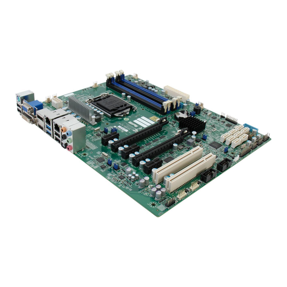
- Page 10 X10SAE User’s Manual X10SAE Motherboard Image Note: All graphics shown in this manual were based upon the latest PCB Revision available at the time of publishing of the manual. The motherboard you've received may or may not look exactly the same as the graphics shown in this manual.
- Page 11 Chapter 1: Introduction X10SAE Motherboard Layout USB 2/3 USB10/11(3.0) JPAC1 JPL2 HDMI/DP VGA/DVI HD AUDIO USB 0/1 JSPDIF_OUT LAN2 LAN1 JHD_AC1 JPW2 JPL1 JI2C1 JI2C2 X10SAE Rev. 1.01 BAR CODE MAC CODE 1394 CODE BIOS LICENSE Always populate blue sockets first;...
- Page 12 X10SAE User’s Manual X10SAE Quick Reference USB 10/11 USB 2/3 USB 0/1 JPL2 JPAC1 HDMI/DP HD AUDIO JSPDIF_OUT KB/MOUSE LAN 1 LAN 2 JHD_AC1 COM4 JPW2 JPL1 JI2C1 JI2C2 X10SAE Rev. 1.01 LV33 JPME2 Battery DIMMA1 DIMMA2 JBT1 DIMMB1 BIOS...
- Page 13 USB 4/5, USB 6/7, USB 8/9 Front Panel Accessible USB 2.0 Headers 4/5, 6/7, 8/9 USB 3.0 12/13, 14/15 Front Panel Accessible USB 3.0 Headers 12/13, 14/15 VGA/DVI Backpanel VGA/DVI (Digital Video Interface) Port X10SAE LED Indicators Description Color/State Status LED1 Onboard Standby PWR LED...
- Page 14 X10SAE User’s Manual Motherboard Features Single Intel® Xeon E3-1200V3 series processor or 4th Generation Intel® Core™ i7/i5/i3 DT processor in an LGA1150 socket Memory Four (4) SDRAM slots support up to 32 GB of DDR3 Unbuffered ECC/Non-ECC 1600/1333/1066 MHz memory...
- Page 15 Chapter 1: Introduction Audio One (1) High Definition Multimedia Interface (HDMI)/DP on the back panel, One (1) High Definition Audio 7.1 channel connector sup- ported by Realtek ALC1150 on the back panel One (1) Front Panel Audio Header One (1) SPDIF_Out on the rear side of the chassis Super I/O Nuvoton NCT6776D BIOS...
- Page 16 X10SAE User’s Manual X10SAE Block Diagram PCIe3.0_x16 PCIe x16 SLOT #6 8.0GT/s VRD12.5 SVID PCIe3.0_x8 VRM 12.5 8.0GT/s INTEL LGA1150 ASMedia Switch PCIe3.0_x8 PCIe3.0_x8 ASM1480 8.0GT/s 8.0GT/s (Socket-H3) DDR3 (CHA) DIMM1A (Blue) Display Port DIMM1B (Black) 1600/1333/1066MHz PCIe x8 SLOT #4...
- Page 17 Chapter 1: Introduction Chipset Overview The X10SAE supports a single Intel® Xeon E3-1200V3 series processor or a 4th Generation Intel® Core i7/i5/i3 DT processor in the LGA 1150 Socket. Built upon the functionality and the capability of the C226 Express chipset, the motherboard provides substantial enhancement to system performance and storage capability for high performance platforms in a sleek package.
- Page 18 X10SAE User’s Manual Special Features Recovery from AC Power Loss Basic I/O System (BIOS) provides a setting for you to determine how the system will respond when AC power is lost and then restored to the system. You can choose for the system to remain powered off, (in which case you must press the power switch to turn it back on), or for it to automatically return to a power-on state.
- Page 19 Chapter 1: Introduction ACPI Features ACPI stands for Advanced Configuration and Power Interface. The ACPI specifica- tion defines a flexible and abstract hardware interface that provides a standard way to integrate power management features throughout a PC system, including its hardware, operating system and application software. This enables the system to automatically turn on and off peripherals such as CD-ROMs, network cards, hard disk drives and printers.
- Page 20 X10SAE User’s Manual It is strongly recommended that you use a high quality power supply that meets ATX power supply Specification 2.02 or above. It must also be SSI compliant. (For more information, please refer to the web site at http://www.ssiforum.org/). Additionally, in areas where noisy power transmission is present, you may choose to install a line filter to shield the computer from noise.
Need help?
Do you have a question about the X10SAE and is the answer not in the manual?
Questions and answers