Table of Contents
Advertisement
Quick Links
Advertisement
Table of Contents

Related Manuals for Supermicro X10SDE-DF


Summary of Contents for Supermicro X10SDE-DF
- Page 1 X10SDE-DF USER MANUAL Revision 1.0a...
- Page 2 State of California, USA. The State of California, County of Santa Clara shall be the exclusive venue for the resolution of any such disputes. Supermicro's total liability for all claims will not exceed the price paid for the hardware product.
- Page 3 About This Manual This manual is written for system integrators, IT technicians and knowledgeable end users. It provides information for the installation and use of the X10SDE-DF motherboard. About This Motherboard The Super X10SDE-DF motherboard supports two Intel® Xeon-D processors in two System- on-Chip (SoC).
- Page 4 X10SDE-DF User Manual Contacting Supermicro Headquarters Address: Super Micro Computer, Inc. 980 Rock Ave. San Jose, CA 95131 U.S.A. Tel: +1 (408) 503-8000 Fax: +1 (408) 503-8008 Email: marketing@supermicro.com (General Information) support@supermicro.com (Technical Support) Website: www.supermicro.com Europe Address: Super Micro Computer B.V.
-
Page 5: Table Of Contents
Preface Table of Contents Chapter 1 Introduction 1.1 Checklist ..........................7 Quick Reference .......................10 Quick Reference Table ......................11 Motherboard Features .......................12 1.2 Processor Overview ......................15 Intel Xeon D-1500 Processor Features ................15 1.3 Special Features ........................15 Recovery from AC Power Loss ..................15 1.4 System Health Monitoring ....................16 Onboard Voltage Monitors ....................16 Fan Status Monitor with Firmware Control ...............16... - Page 6 X10SDE-DF User Manual 2.4 Front I/O Ports ........................24 2.5 Switches ..........................26 2.6 Jumper Settings .........................27 How Jumpers Work ......................27 2.7 LED Indicators ........................32 Chapter 3 Troubleshooting 3.1 Troubleshooting Procedures ....................35 Before Power On ......................35 No Power ..........................35 No Video ...........................35 Memory Errors ........................36...
-
Page 7: Chapter 1 Introduction
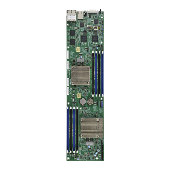
• Product safety info: http://www.supermicro.com/about/policies/safety_information.cfm • If you have any questions, please contact our support team at: support@supermicro.com This manual may be periodically updated without notice. Please check the Supermicro website for possible updates to the manual revision level. - Page 8 X10SDE-DF User Manual Figure 1-1. X10SDE-DF Motherboard Image Note: All graphics shown in this manual were based upon the latest PCB revision available at the time of publication of the manual. The motherboard you received may or may not look exactly the same as the graphics shown in this manual.
- Page 9 Chapter 1: Introduction Figure 1-2. X10SDE-DF Motherboard Layout (not drawn to scale) CPU1 P1-JBT1 P1-JBR1 P2-BT1 P1-JPME1 P1-JPME2 P2-JBR1 P2-JPME1 P2-JPME2 P1-BT1 P2-JBT1 CPU2 P1-JPL1 LEDM2 LEDM1 i350 LAN P2-JPG1 P2-JPL1 P1-JPG1 i350 LAN P1-JPB1 P2-JWD1 P1-JWD1 IPMI_LAN P1 LAN2...
-
Page 10: Quick Reference
X10SDE-DF User Manual Quick Reference P1-DIMMB2 P1-DIMMB1 P1-DIMMA2 P1-DIMMA1 CPU1 P1-JBT1 P1-JBR1 P1-JBT1 P2-BT1 P1-JPME1 P1-JPME2 P1-JBR1 P1-JPME1 P2-BT1 P2-JBR1 P1-JPME2 P2-JBR1 P1-BT1 P2-JPME1 P2-JPME2 P2-JPME1 P1-BT1 P2-JPME2 P2-JBT1 P2-JBT1 P2-DIMMB2 P2-DIMMB1 CPU2 P2-DIMMA2 P2-DIMMA1 P1-JPL1 P1-JPL1 LEDM2 LEDM1 LEDM2... -
Page 11: Quick Reference Table
Chapter 1: Introduction Quick Reference Table Jumper Description Default Setting P1/P2-JBR1 BIOS Recovery Pins 1-2 (Normal) P1/P2-JBT1 CMOS Clear See Chapter 2 P1/P2-JPB1 BMC Enable/Disable Pins 1-2 (Enabled) P1/P2-JPG1 VGA Enable/Disable Pins 1-2 (Enabled) P1/P2-JPL1 LAN1/2 Enable/Disable Pins 1-2 (Enabled) P1/P2-JPME1 ME Recovery Pins 1-2 (Normal) -
Page 12: Motherboard Features
32GB, 16GB, 8GB, and 4GB, up to 128GB for RDIMM memory or up to 64GB for UDIMM memory at 1.2V Note 1: Memory speed support depends on the processors used in the system. Note 2: For the latest CPU/memory updates, please refer to our website at http://www.supermicro.com/products/ motherboard. - Page 13 User's Guide available at http://www.supermicro.com/support/manuals/. Note 3: It is strongly recommended that you change BMC log-in information upon ini- tial system power-on. The manufacture default username is ADMIN and the password is ADMIN. For proper BMC configuration, please refer to http://www.supermicro.com/ products/info/files/IPMI/Best_Practices_BMC_Security.pdf...
- Page 14 X10SDE-DF User Manual Figure 1-3. System Block Diagram CPU1 CPU2 DIMMA2 DIMMA1 DIMMA2 DIMMA1 FLASH 128Mbit FLASH 128Mbit DIMMB2 DIMMB1 DIMMB2 DIMMB1 HDD Backplane SATA GEN3 Pericom SATA GEN3 Pericom 6812 6812 SATA SATA SATA 3.0 SATA 3.0 re-driver re-driver...
-
Page 15: Processor Overview
Chapter 1: Introduction 1.2 Processor Overview The Intel® Xeon D-1500 product family is the third generation, low-powered 64-bit SoC (System-on-a-Chip) processor that is optimized to deliver high performance, energy effiency and enhanced total cost of ownership solutions. The low-power consumption of the processor makes it suitable for dense servers that can effectively take on hyperscale workloads, intelligent edge network or ultra-dense embedded devices. -
Page 16: System Health Monitoring
X10SDE-DF User Manual 1.4 System Health Monitoring Onboard Voltage Monitors The onboard voltage monitor will continuously scan crucial voltage levels. Once a voltage becomes unstable, it will give a warning or send an error message to the screen. Users can adjust the voltage thresholds to define the sensitivity of the voltage monitor. -
Page 17: Power Supply
1.7 Serial Port The X10SDE-DF motherboard supports one serial communication connection via KVM. The UART provides legacy speeds with a baud rate of up to 115.2 Kbps as well as an advanced speed with baud rates of 250 K, 500 K, or 1 Mb/s, which support high-speed serial... -
Page 18: Chapter 2 Installation
X10SDE-DF User Manual Chapter 2 Installation 2.1 Static-Sensitive Devices Electrostatic Discharge (ESD) can damage electronic com ponents. To prevent damage to your motherboard, it is important to handle it very carefully. The following measures are generally sufficient to protect your equipment from ESD. -
Page 19: Motherboard Installation
Chapter 2: Installation 2.2 Motherboard Installation All motherboards have standard mounting holes to fit different types of chassis. Make sure that the locations of all the mounting holes for both the motherboard and the chassis match. Although a chassis may have both plastic and metal mounting fasteners, metal ones are highly recommended because they ground the motherboard to the chassis. -
Page 20: Installing The Motherboard
X10SDE-DF User Manual Installing the Motherboard 1. Locate the mounting holes on the motherboard. See the previous page for the location. 2. Locate the matching mounting holes on the motherboard mounting tray. Install standoffs needed. Align the mounting holes on the mothreboard against the mounting holes on the motherboard tray. -
Page 21: Memory Support And Installation
Memory Support The X10SDE-DF supports DDR4 VLP ECC memory; up to 64GB of unbuffered (UDIMM) memory or up to 128GB of registered (RDIMM) memory in four memory slots per node. Node 1 has slots P1-DIMMA1, P1-DIMMA2, P1-DIMMB1, and P1-DIMMB2. Node 2 has slots P2- DIMMA1, P2-DIMMA2, P2-DIMMB1, and P2-DIMMB2. -
Page 22: Dimm Module Population Sequence
X10SDE-DF User Manual Memory Module Population Max Memory 4GB DRAM 8GB DRAM Possible Technology Technology Single Rank 16GB 32GB UDIMM (4x 4GB DIMMs) (4x 8GB DIMMs) Dual Rank 32GB 64GB UDIMMs (4x 8GB DIMMs) (4x 16GB DIMMs) Speed (MT/s); Voltage (V);... -
Page 23: Dimm Installation
Chapter 2: Installation DIMM Installation 1. Insert DIMM modules in the following order: P1-DIMMA1, P1-DIMMB1, P1- DIMMA2, P1-DIMMB2, then P2-DIMMA1, P2-DIMMB1, P2-DIMMA2, P2-DIMMB2. CPU1 For the system to work properly, please P1-JBT1 use memory modules of the same type P1-JBR1 P1-JPME1 P2-BT1 P1-JPME2... -
Page 24: Front I/O Ports
X10SDE-DF User Manual 2.4 Front I/O Ports See Figure 2-2 below for the locations and descriptions of the various I/O ports on the front of the motherboard. CPU1 P1-JBT1 P1-JBR1 P1-JPME1 P2-BT1 P1-JPME2 P2-JBR1 P2-JPME1 P2-JPME2 P1-BT1 P2-JBT1 CPU2 P1-JPL1... - Page 25 Chapter 2: Installation KVM Connector KVM supports two USB 2.0 ports, KVM, VGA, and COM (UART) connections via dongle on the I/O back panel to provide console redirection support or remote networking interface. LAN Ports Two Gigabit Ethernet ports (LAN1/2) for each node are located on the back panel to provide Internet connection.
-
Page 26: Switches
X10SDE-DF User Manual 2.5 Switches Power Switch/LED Indicator A power switch (SW1) is located next to the KVM connector on the back panel of the motherboard. Use this switch to turn on and off the power supply for both Node 1 and Node 2. -
Page 27: Jumper Settings
Chapter 2: Installation 2.6 Jumper Settings How Jumpers Work To modify the operation of the motherboard, jumpers can be used to choose between optional settings. Jumpers create shorts between two pins to change the function of the connector. Pin 1 is identified with a square solder pad on the printed circuit board. See the diagram below for an example of jumping pins 1 and 2. - Page 28 X10SDE-DF User Manual CMOS Clear P1-JBT1 is used to clear the saved system setup configuration stored in the CMOS chip for Node 1, while P2-JBT1 is used for Node 2. To clear the contents of the CMOS, completely shut down the system, remove the AC power cord connection, and then short P1-JBT1 or P2-JBT1 with a jumper.
- Page 29 Chapter 2: Installation Watch Dog Watch Dog is a system monitor that can reboot the system when a software application hangs. Close pins 1-2 on P1-JWD1 (for Node 1) or P2-JWD1 (for Node 2) to reset the system if an application hangs. Close pins 2-3 of P1-JWD1 or P2-JWD1 to generate a non-maskable interrupt signal for the application that hangs.
- Page 30 X10SDE-DF User Manual BMC Enable/Disable JPB1 is used to enable or disable the BMC (Baseboard Management Control) chip (P1-JPB1 for Node 1, P2-JPB1 for Node 2) and the onboard IPMI connection. This jumper is used together with the IPMI settings in the BIOS. Refer to the table below for jumper settings.
- Page 31 Chapter 2: Installation Management Engine (ME) Recovery Set jumpers P1-JPME1/P2-JPME1 to select ME Firmware Recovery mode for Node 1 (P1- JPME1) or Node 2 (P2-JPME1). ME Recovery limits system resource for essential function use only without putting restrictions on power use. In the single-operation mode, online upgrade will be available via Recovery mode.
-
Page 32: Led Indicators
X10SDE-DF User Manual 2.7 LED Indicators LAN1/2 LEDs The LAN 1/2 ports for Node 1 and Node 2 are located on the I/O back panel. Each Ethernet LAN port has two LEDs. The yellow LED on the right indicates the link. The Activity LED on the left may be green, amber, or off to indicate the speed. - Page 33 Note: UID can also be triggered via the IPMI on the motherboard. For more informa- tion on the IPMI, please refer to the IPMI User's Guide posted on our website at http:// www.supermicro.com UID LED Indicator LED Color...
- Page 34 X10SDE-DF User Manual BMC Heartbeat LEDs Two BMC Heartbeat LEDs are located on the motherboard. When LEDM1 is blinking, the BMC is functioning normally for Node 1. When LEDM2 is blinking, the BMC is functioning normally for Node 2. Refer to the table below for more information.
-
Page 35: Chapter 3 Troubleshooting
Chapter 3: Troubleshooting Chapter 3 Troubleshooting 3.1 Troubleshooting Procedures Use the following procedures to troubleshoot your system. If you have followed all of the procedures below and still need assistance, refer to the ‘Technical Support Procedures’ and/ or ‘Returning Merchandise for Service’ section(s) in this chapter. Always disconnect the AC power cord before adding, changing or installing any non hot-swap hardware components. -
Page 36: Memory Errors
1. Make sure that the DIMM modules are properly installed and fully seated in the slots. 2. You should be using memory recommended by Supermicro (see Section 2-4). Also, it is recommended that you use the memory modules of the same type and speed for all DIMMs in the system. -
Page 37: Technical Support Procedures
Chapter 3: Troubleshooting 3.2 Technical Support Procedures Before contacting Technical Support, please take the following steps. Also, note that as a motherboard manufacturer, we do not sell directly to end-users, so it is best to first check with your distributor or reseller for troubleshooting services. They should know of any possible problem(s) with the specific system configuration that was sold to you. -
Page 38: Frequently Asked Questions
3.3 Frequently Asked Questions Question: What type of memory does my motherboard support? Answer: The X10SDE-DF motherboard supports DDR4 2133MHz VLP ECC memory; up to 64GB of UDIMM memory or up to 128GB of RDIMM memory. See Section 2.4 for details on installing memory. -
Page 39: Battery Removal And Installation
Chapter 3: Troubleshooting 3.4 Battery Removal and Installation Battery Removal To remove the onboard battery, follow the steps below: 1. Power off your system and unplug your power cable. 2. Locate the onboard battery as shown below. 3. Using a tool such as a pen or a small screwdriver, push the battery lock outwards to unlock it. -
Page 40: Returning Merchandise For Service
X10SDE-DF User Manual 3.5 Returning Merchandise for Service A receipt or copy of your invoice marked with the date of purchase is required before any warranty service will be rendered. You can obtain service by calling your vendor for a Returned Merchandise Authorization (RMA) number. -
Page 41: Chapter 4 Bios
BIOS 4.1 Introduction This chapter describes the AMIBIOS™ Setup utility for the X10SDE-DF motherboard. The BIOS is stored on a chip and can be easily upgraded using a flash program. Note: Due to periodic changes to the BIOS, some settings may have been added or deleted and might not yet be recorded in this manual. -
Page 42: Main Setup
X10SDE-DF User's Manual 4.2 Main Setup When you first enter the AMI BIOS setup utility, you will enter the Main setup screen. You can always return to the Main setup screen by selecting the Main tab on the top of the screen. - Page 43 Chapter 4: BIOS Memory Information Total Memory This item displays the total size of memory available in the system. Memory Speed This item displays the memory speed.
-
Page 44: Advanced Setup Configurations
X10SDE-DF User's Manual 4.3 Advanced Setup Configurations Use the arrow keys to select Advanced Setup and press <Enter> to access the submenu items. Warning: Take caution when changing the Advanced settings. An incorrect value, a very high DRAM frequency, or an incorrect DRAM timing setting may make the system unstable. When this occurs, revert to the manufacture default settings. - Page 45 Chapter 4: BIOS Wait For 'F1' If Error Use this feature to force the system to wait until the 'F1' key is pressed if an error occurs. The options are Disabled and Enabled. INT19 (Interrupt 19) Trap Response Interrupt 19 is the software interrupt that handles the boot disk function. When this item is set to Immediate, the ROM BIOS of the host adaptors will "capture"...
- Page 46 X10SDE-DF User's Manual • Processor Frequency • Processor Max Ratio • Processor Min Ratio • Microcode Revision • L1 Cache RAM • L2 Cache RAM • L3 Cache RAM • CPU Version Clock Spread Spectrum If this feature is set to Enabled, the BIOS utility will monitor the level of Electromagnetic Interference caused by the components and will attempt to reduce the interference whenever needed.
- Page 47 Chapter 4: BIOS Hardware Prefetcher (Available when supported by the CPU) If set to Enabled, the hardware prefetcher will prefetch streams of data and instructions from the main memory to the L2 cache to improve CPU performance. The options are Disable and Enable.
- Page 48 X10SDE-DF User's Manual CPU P State Control P State Domain This feature allows the user to indicate the P-State domain for each logical process in the system. All processes indicate the same domain in the same package. The options are ALL and ONE.
- Page 49 Chapter 4: BIOS Package C State Limit This feature allows the user to set the limit on the C State package register. The options are C0/C1 State, C2 State, C6 (Non Retention) State, and C6 (Rentention) state. CPU C3 Report Select Enabled to allow the BIOS to report the CPU C3 State (ACPI C2) to the operating system.
- Page 50 X10SDE-DF User's Manual Power/Performance Switch This feature allows dynamic switching between Power and Performance power efficiency. The options are Disable and Enable. Workload Configuration This feature allows for optimization of workload. Balanced is recommended. The options are Balanced and I/O Sensitive.
- Page 51 Chapter 4: BIOS IIO Configuration EV DFX (Device Function On-Hide) Features When this feature is set to Enable, the EV_DFX Lock Bits that are located on a processor will always remain clear during electric tuning. The options are Disable and Enable. IOAT (Intel IO Acceleration) Configuration ®...
- Page 52 X10SDE-DF User's Manual Memory Frequency Use this feature to set the maximum memory frequency for onboard memory modules. The options are Auto, 1333, 1400, 1600, 1800, 1867, 2000, 2133, 2200, 2400, 2600, 2667, 2800, 2993, 3000, 3200, and Reserved (Do not select Reserved).
- Page 53 Chapter 4: BIOS Patrol Scrub Interval This feature allows you to decide how many hours the system should wait before the next complete patrol scrub is performed. Use the keyboard to enter a value from 0-24. The default setting is 24. Demand Scrub Demand Scrubbing is a process that allows the CPU to correct correctable memory errors found on a memory module.
- Page 54 X10SDE-DF User's Manual EHCI1 Select Enabled to enable EHCI (Enhanced Host Controller Interface) support on USB 2.0 connector #1 (at least one USB 2.0 connector should be enabled for EHCI support). The options are Disabled and Enabled. EHCI2 Select Enabled to enable EHCI (Enhanced Host Controller Interface) support on USB 2.0 connector #2 (at least one USB 2.0 connector should be enabled for EHCI support).
- Page 55 Chapter 4: BIOS P1-SATA0 ~ P1-SATA1 This item displays the information detected on the installed SATA drive on the particular SATA port. • Model number of drive and capacity • Software Preserve Support P1-SATA0 ~ P1-SATA1 Hot Plug Set this item to Enabled for hot-plugging support, which will allow the user to replace a SATA drive without shutting down the system.
- Page 56 X10SDE-DF User's Manual PCI PERR/SERR Support Select Enabled to allow a PCI device to generate a PERR/SERR number for a PCI Bus Signal Error Event. The options are Disabled and Enabled. SR-IOV Support Use this feature to enable or disable Single Root IO Virtualization Support. The options are Disabled and Enabled.
- Page 57 Chapter 4: BIOS Onboard Video Option ROM Use this item to select the Onboard Video Option ROM type. The options are Disabled, Legacy, and EFI. VGA Priority This feature allows the user to select the graphics adapter to be used as the primary boot device.
- Page 58 X10SDE-DF User's Manual Serial Port 1 Change Settings This feature specifies the base I/O port address and the Interrupt Request address of a serial port specified by the user. Select Auto to allow the BIOS to automatically assign the base I/O and IRQ address.
- Page 59 Chapter 4: BIOS Parity A parity bit can be sent along with regular data bits to detect data transmission errors. Select Even if the parity bit is set to 0, and the number of 1's in data bits is even. Select Odd if the parity bit is set to 0, and the number of 1's in data bits is odd.
- Page 60 X10SDE-DF User's Manual SOL Console Redirection Select Enabled to use the SOL port for Console Redirection. The options are Disabled and Enabled. *If the item above set to Enabled, the following items will become available for configuration: SOLConsole Redirection Settings Use this feature to specify how the host computer will exchange data with the client computer, which is the remote computer used by the user.
- Page 61 Chapter 4: BIOS Flow Control Use this feature to set the flow control for Console Redirection to prevent data loss caused by buffer overflow. Send a "Stop" signal to stop sending data when the receiving buffer is full. Send a "Start" signal to start sending data when the receiving buffer is empty. The options are None and Hardware RTS/CTS.
- Page 62 X10SDE-DF User's Manual EMS Console Redirection Settings This feature allows the user to specify how the host computer will exchange data with the client computer, which is the remote computer used by the user. Out-of-Band Mgmt Port The feature selects a serial port in a client server to be used by the Microsoft Windows Emergency Management Services (EMS) to communicate with a remote host server.
- Page 63 Chapter 4: BIOS ACPI Settings WHEA Support Select Enabled to support the Windows Hardware Error Architecture (WHEA) platform and provide a common infrastructure for the system to handle hardware errors within the Windows OS environment to reduce system crashes and to enhance system recovery and health monitoring.
-
Page 64: Event Logs
X10SDE-DF User's Manual 4.4 Event Logs Use this feature to configure Event Log settings. Change SMBIOS Event Log Settings Enabling/Disabling Options SMBIOS Event Log Change this item to enable or disable all features of the SMBIOS Event Logging during system boot. - Page 65 Chapter 4: BIOS PCI-Ex (PCI-Express) Error Enable Select Yes for the BIOS to correct errors occurred in the PCI-E slots. The options are Yes and No. Erasing Settings Erase Event Log If No is selected, data stored in the event log will not be erased. Select Yes, Next Reset, data in the event log will be erased upon next system reboot.
-
Page 66: Ipmi
X10SDE-DF User's Manual 4.5 IPMI Use this feature to configure Intelligent Platform Management Interface (IPMI) settings. BMC Firmware Revision This item indicates the IPMI firmware revision used in your system. IPMI Status (Baseboard Management Controller) This item indicates the status of the IPMI firmware installed in your system. - Page 67 Chapter 4: BIOS When SEL is Full This feature allows the user to decide what the BIOS should do when the system event log is full. Select Erase Immediately to erase all events in the log when the system event log is full.
- Page 68 X10SDE-DF User's Manual Gateway IP Address This item displays the Gateway IP address for this computer. This should be in decimal and in dotted quad form (i.e., 172.31.0.1). VLAN Use this item to enable or disable the IPMI VLAN function. The options are Disable and...
-
Page 69: Security
Chapter 4: BIOS 4.6 Security This menu allows the user to configure the following Security settings for the system. Password Check Select Setup for the system to check for a password at Setup. Select Always for the system to check for a password at bootup or upon entering the BIOS Setup utility. The options are Setup and Always. - Page 70 X10SDE-DF User's Manual Secure Boot Use this item to enable secure boot. The options are Disabled and Enabled. Secure Boot Mode Use this item to select the secure boot mode. The options are Standard and Custom. Key Management This submenu allows the user to configure the following Key Management settings.
- Page 71 Chapter 4: BIOS Append Key Select Yes to add the database from the manufacturer's defaults to the existing DB. Select No to load the DB from a file. The options are Yes and No. Forbiden Signatures Set New Key Select Yes to load the DBX from the manufacturer's defaults.
-
Page 72: Boot
X10SDE-DF User's Manual 4.7 Boot Use this feature to configure Boot Settings: Boot Mode Select Use this item to select the type of device that the system is going to boot from. The options are Legacy, UEFI, and Dual. The default setting is Dual. - Page 73 Chapter 4: BIOS • Legacy/UEFI/Dual Boot Order #8 • Legacy/UEFI/Dual Boot Order #9 • Legacy/UEFI/Dual Boot Order #10 • Legacy/UEFI/Dual Boot Order #11 • Legacy/UEFI/Dual Boot Order #12 • Legacy/UEFI/Dual Boot Order #13 • Legacy/UEFI/Dual Boot Order #14 • Legacy/UEFI/Dual Boot Order #15 ...
-
Page 74: Save & Exit
X10SDE-DF User's Manual 4.8 Save & Exit Select the Exit tab from the BIOS setup utility screen to enter the Exit BIOS Setup screen. Discard Changes and Exit Select this option to quit the BIOS Setup without making any permanent changes to the system configuration and reboot the computer. - Page 75 Chapter 4: BIOS Default Options Restore Optimized Defaults To set this feature, select Restore Optimized Defaults from the Save & Exit menu and press <Enter>. These are factory settings designed for maximum system stability but not for maximum performance. Save As User Defaults To set this feature, select Save as User Defaults from the Exit menu and press <Enter>.
-
Page 76: Appendix A Software Installation
Appendix A Software Installation A.1 Installing Software Programs The Supermicro FTP site contains drivers and utilities for your system at ftp://ftp.supermicro. com. Some of these must be installed, such as the chipset driver. After accessing the FTP site, go into the CDR_Images directory and locate the ISO file for your motherboard. -
Page 77: Superdoctor ® 5
A.2 SuperDoctor ® The Supermicro SuperDoctor 5 is a hardware monitoring program that functions in a command-line or web-based interface in Windows and Linux operating systems. The program monitors system health information, such as CPU temperature, system voltages, system power consumption, and fan speed, and provides alerts via email or the Simple Network Management Protocol (SNMP). -
Page 78: Appendix B Standardized Warning Statements
The following statements are industry standard warnings, provided to warn the user of situations which have the potential for bodily injury. Should you have questions or experience difficulty, contact Supermicro's Technical Support department for assistance. Only certified technicians should attempt to install or configure components. - Page 79 Appendix B: Warning Statements Attention Danger d'explosion si la pile n'est pas remplacée correctement. Ne la remplacer que par une pile de type semblable ou équivalent, recommandée par le fabricant. Jeter les piles usagées conformément aux instructions du fabricant. ¡Advertencia! Existe peligro de explosión si la batería se reemplaza de manera incorrecta.
-
Page 80: Product Disposal
X10SDE-DF User Manual Product Disposal Warning! Ultimate disposal of this product should be handled according to all national laws and regulations. 製品の廃棄 この製品を廃棄処分する場合、 国の関係する全ての法律 ・ 条例に従い処理する必要があります。 警告 本产品的废弃处理应根据所有国家的法律和规章进行。 警告 本產品的廢棄處理應根據所有國家的法律和規章進行。 Warnung Die Entsorgung dieses Produkts sollte gemäß allen Bestimmungen und Gesetzen des Landes erfolgen. -
Page 81: Appendix C Uefi Bios Recovery
Warning: Do not upgrade the BIOS unless your system has a BIOS-related issue. Flashing the wrong BIOS can cause irreparable damage to the system. In no event shall Supermicro be liable for direct, indirect, special, incidental, or consequential damages arising from a BIOS update. - Page 82 Directory of a USB device or a writeable CD/DVD. Note: If you cannot locate the "Super.ROM" file in your driver disk, visit our website at www.supermicro.com to download the BIOS image into a USB flash device and rename it to "Super.ROM" for BIOS recovery use.
- Page 83 Appendix C: UEFI BIOS Recovery 5. When the screen as shown above displays, use the arrow keys to select the item "Proceed with flash update" and press the <Enter> key. You will see the BIOS recovery progress as shown in the screen below. Aptio Setup Utility - Copyright (C) 2011 American Megatrends, Inc.
- Page 84 X10SDE-DF User Manual 9. After seeing the message that BIOS update has completed, unplug the AC power cable from the power supply, clear CMOS, then plug the AC power cable in the power supply again to power on the system.
Need help?
Do you have a question about the X10SDE-DF and is the answer not in the manual?
Questions and answers