Sign In
Upload
Manuals
Brands
Supermicro Manuals
Motherboard
X10SRG-F
Supermicro X10SRG-F Manuals
Manuals and User Guides for Supermicro X10SRG-F. We have
1
Supermicro X10SRG-F manual available for free PDF download: User Manual
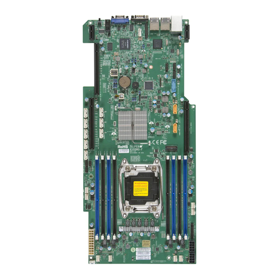
Supermicro X10SRG-F User Manual (137 pages)
Brand:
Supermicro
| Category:
Motherboard
| Size: 13 MB
Table of Contents
About this Motherboard
3
Conventions Used in the Manual
4
Contacting Supermicro
5
Table of Contents
6
Chapter 1 Introduction
15
Overview
15
Checklist
15
Motherboard Features
21
System Block Diagram
23
Chipset Overview
24
Intel C612 Chipset Features
24
Special Features
25
Recovery from AC Power Loss
25
PC Health Monitoring
25
Fan Status Monitor with Firmware Control
25
Environmental Temperature Control
25
System Resource Alert
26
ACPI Features
26
Slow Blinking LED for Suspend-State Indicator
26
Power Supply
26
Chapter 2 Installation
29
Static-Sensitive Devices
29
Precautions
29
Unpacking
29
Motherboard Installation
30
Tools Needed
30
Location of Mounting Holes
30
Installing the Motherboard
31
Processor and Heatsink Installation
32
Opening the LGA2011 Socket
32
Installing the LGA2011 Processor
34
Installing a Passive CPU Heatsink
36
Removing the Heatsink
37
Installing DDR4 Memory
38
DIMM Installation
38
Removing Memory Modules
38
Memory Support
39
Memory Population Guidelines
39
Connectors/Io Ports
42
Motherboard I/O Backpanel
42
Universal Serial Bus (USB)
43
Ethernet Ports (LAN1/LAN2)
44
IPMI Port (IPMI)
44
Serial Ports
44
Unit Identifier Switch (UID)
45
VGA Connector (VGA)
45
Front Control Panel
46
Front Control Panel Pin Definitions
47
Hdd Led
47
Power Fail LED
47
Power LED
47
Nic1/Nic2 (Lan1/Lan2)
48
Overheat (Oh)/Fan Fail/Unit ID LED
48
NMI Button
49
Power Button
49
Reset Button
49
Connecting Cables & Optional Devices
50
Main PWR (JPW1) & GPU PWR Connectors (JPW2, JPW3)
50
Fan Headers (FAN1~4, FANA~D)
51
Chassis Intrusion (JL1)
51
Legacy Wake-On-LAN Header (JSTBY1)
52
System Management Bus (JIPMB1 )
52
Power Supply I2C (JPI2C1)
53
DOM PWR Connector (JSD1/JSD2)
53
I-Sgpio1/I-Sgpio2/S-Sgpio
54
TPM Header (JTPM1)
54
Overheat/Fan Fail LED (JOH1 )
55
Speaker (JD1)
55
Internal Buzzer (SP1)
56
Jumper Settings
57
Explanation of Jumpers
57
LAN Port Enable/Disable (JPL1)
57
Clear CMOS (JBT1)
58
PCI Slot SMB Enable (JI2C1/JI2C2)
58
VGA Enable (JPG1)
59
Watch Dog Reset (JWD1)
59
BMC Enable/Disable (JPB1)
60
Manufacturer Mode Select (JPME2)
60
BIOS Recovery (JBR1)
61
I 2 C Bus for VRM
61
Onboard Indicators
62
LAN Port Leds
62
IPMI Heartbeat LED (LEDM1)
62
Unit Identification LED (LE1)
63
Onboard Power LED (LE2)
63
SATA Connections
64
SATA/SAS Connections
64
Chapter 3 Troubleshooting
65
Troubleshooting Procedures
65
Before Power on
65
No Power
65
No Video
66
Memory Errors
66
When You Lose the System's Setup Configuration
66
Technical Support Procedures
67
Frequently Asked Questions
68
Battery Removal and Installation
70
Battery Removal
70
Proper Battery Disposal
70
Battery Installation
70
Returning Merchandise for Service
71
Chapter 4 BIOS
73
Introduction
73
Starting BIOS Setup Utility
73
How to Change the Configuration Data
73
How to Start the Setup Utility
74
Main Setup
74
The Following Main Menu Items will be Displayed
74
System Date/System Time
75
Supermicro X10SRG-F
75
BIOS Version
75
Build Date
75
Memory Information
75
Total Memory
75
Memory Speed
75
Advanced Setup Configurations
76
Boot Feature
76
Quiet Boot
76
Addon ROM Display Mode
76
Bootup Num-Lock
77
Wait for 'F1' if Error
77
INT19 (Interrupt 19) Trap Response
77
Re-Try Boot
77
Power Configuration
77
Deepsx Power Policies
77
GP27 Wake from Deepsx
77
Watch Dog Function
78
Power Button Function
78
Restore on AC Power Loss
78
CPU Configuration
78
CPU1/CPU2 Configuration
78
Adjacent Cache Line Prefetch (Available When Supported by the CPU)
79
Clock Spread Spectrum
79
Cores Enabled
79
Execute Disable Bit (Available if Supported by the os & the CPU)
79
Hardware Prefetcher (Available When Supported by the CPU)
79
Hyper-Threading (ALL)
79
PPIN Control
79
Aes-Ni
80
DCA Prefetch Delay
80
DCU IP Prefetcher
80
DCU Streamer Prefetcher (Available When Supported by the CPU)
80
Direct Cache Access (DCA)
80
Intel Virtualization Technology
80
X2APIC (Extended Advanced Programmable Interrupt Controller)
80
Advanced Power Management Configuration
81
Chipset Configuration
83
North Bridge
83
IIO Configuration
83
Intel VT for Directed I/O (VT-D)
84
QPI (Quick Path Interconnect) Configuration
84
Memory Configuration
85
DIMM Information
86
South Bridge
87
Legacy USB Support
87
XHCI Hand-Off
87
EHCI Hand-Off
88
Ehci1
88
Ehci2
88
Port 60/64 Emulation
88
SATA Configuration
88
SATA Controller
88
USB 3.0 Support
88
XHCI Pre-Boot Driver
88
Configure SATA as
89
Configure Ssata as
91
Ssata Configuration
91
Ssata Controller
91
Server ME (Management Engine) Configuration
92
Pcie/Pci/Pnp Configuration
93
Above 4G Decoding (Available if the System Supports 64-Bit PCI Decoding)
93
PCI Latency Timer
93
PCI PERR/SERR Support
93
PCI-X Latency Timer
93
PERR# Generation
93
SERR# Generation
93
The Following PCI Information will be Displayed
93
ASPM Support
94
Maximum Payload
94
Maximum Read Request
94
MMIO High Size
94
Mmiohbase
94
RSC-R1UFF-E16 CPU1 SLOT1 PCI-E X16 OPROM
94
RSC-R1UFF-E16 CPU1 SLOT2 PCI-E X16 OPROM
94
SR-IOV Support (Available if the System Supports Single-Root Virtualization)
94
Ipv4 PXE Support
95
Ipv6 PXE Support
95
Load Onboard SAS Option ROM
95
Network Stack
95
Onboard LAN Option ROM Type
95
Onboard LAN1 Option ROM
95
Onboard LAN2 Option ROM
95
Onboard Video Option ROM
95
PXE Boot Wait Time
95
VGA Priority
95
Change Port 1 Settings
96
Device Settings
96
Media Detect Time
96
Serial Port 1
96
Serial Port 1 Configuration
96
Serial Port 2
96
Serial Port 2 Configuration
96
Change Port 2 Settings
97
Serial Port 2 Attribute
97
Serial Port Console Redirection
97
COM1 Console Redirection
97
SOL/COM2 Console Redirection Settings
99
Serial Port for Out-Of-Band Management/Windows Emergency Management Services (EMS)
101
EMS (Emergency Management Services) Console Redirection
101
EMS Console Redirection Settings
101
ACPI Settings
103
Use this Feature to Configure Advanced Configuration and Power Interface (ACPI) Power Management Settings for Your System
103
WHEA Support
103
High Precision Timer
103
NUMA Support (Available When the os Supports this Feature)
103
PCI AER Support
103
Trusted Computing (Available When a TPM Device Is Installed and Detected by the BIOS)
104
Configuration
104
Security Device Support
104
TPM State
104
Pending Operation
104
Current Status Information
104
Intel TXT (LT-SX) Confirguration
104
Intel® I350 Gigabit Network Connections
106
NIC Configuration
106
Blink Leds
106
Port Configuration Information
106
Intel Rste SATA Controller
107
SATA RAID Legacy Oprom
107
Uefi Sata Raid
107
Event Logs
108
Change SMBIOS Event Log Settings
108
Enabling/Disabling Options
108
Memory Correctable Error Threshold
108
Memory Corrected Error Enabling (Available When the Item Above-Runtime Error Logging Support Is Set to Enable)
108
PCI-Ex (PCI-Express) Error Enable
108
Runtime Error Logging Support
108
SMBIOS Event Log
108
Erase Event Log
109
Erasing Settings
109
Log System Boot Event
109
MECI (Multiple Event Count Increment)
109
METW (Multiple Event Count Time Window)
109
SMBIOS Event Log Standard Settings
109
When Log Is Full
109
Ipmi
110
IPMI Firmware Revision
110
IPMI Status
110
System Event Log
110
Enabling/Disabling Options
110
Erase SEL
110
Erasing Settings
110
SEL Components
110
When SEL Is Full
111
BMC Network Configuration
111
Configuration Address Source
111
IPMI LAN Selection
111
IPMI Network Link Status
111
Update IPMI LAN Configuration
111
Security Settings
113
Password Check
113
Administrator Password
113
Boot Settings
114
Setup Prompt Timeout
114
Boot Mode Select
114
Fixed Boot Order Priorities
114
Add New Boot Option
115
Boot Option File Path
115
Delete Boot Option
115
Hard Disk Drive BBS Priorities
115
Network Drive BBS Priorities
116
UEFI Application Boot Priorities
116
UEFI USB Key Drive BBS Priorities
116
USB Key Drive BBS Priorities
116
Save & Exit
117
Discard Changes and Exit
117
Save Changes and Reset
117
Save Options
118
Save Changes
118
Discard Changes
118
Restore Defaults
118
Save as User Defaults
118
Restore User Defaults
118
Boot Override
118
Appendix A BIOS Error Beep Codes
119
A-1 BIOS Error Beep Codes
119
Appendix B Software Installation Instructions
121
B-1 Installing Software Programs
121
B-2 Installing Superdoctor5
122
Appendix C UEFI BIOS Recovery Instructions
123
C-1 an Overview to the UEFI BIOS
123
How to Recover the UEFI BIOS Image (-The Main BIOS Block
123
To Recover the Main BIOS Block Using a USB-Attached Device
123
Appendix D Dual Boot Block on Grantley Platforms
127
D-1 IPMI GUI Browser
128
D-2 IPMI Command Sets
133
User Approach
135
Advertisement
Advertisement
Related Products
Supermicro Supero X10SRL-F
Supermicro X10SRM-F
Supermicro X10SRM-TF
Supermicro X10SRW-F
Supermicro X10SRD-F
Supermicro X10SRi-F
Supermicro X10SRH-CF/CLN4F
Supermicro X10SLD-F
Supermicro X10SDV-F
Supermicro X10SBA
Supermicro Categories
Server
Motherboard
Computer Hardware
Chassis
Switch
More Supermicro Manuals
Login
Sign In
OR
Sign in with Facebook
Sign in with Google
Upload manual
Upload from disk
Upload from URL