
Subscribe to Our Youtube Channel
Related Manuals for Emerson RTS FQ


Summary of Contents for Emerson RTS FQ
- Page 1 User Instructions User Instructions Part Number IOM DS – 87376-4, Rev. 1.0 Part Number IOM – 87376-7 July 2016, Rev 1. Release: July 2016 Operating Manual for Bettis RTS FQ Fail-Safe Quarter-Turn Actuator...
-
Page 2: Part Number Iom
User Instructions Part Number IOM – 87376-7 July 2016, Rev 1.0... -
Page 3: Table Of Contents
User Instructions Part Number IOM – 87376-7 July 2016, Rev 1. Table of Contents Section 1: Introduction Section 2: Functional Description of the RTS FQ Fail-Safe Quarter-Turn Actuator Section 3: General Information Safety Instructions ........................4 Direction of Rotation ........................4 Section 4: Packaging, Transport and Storage General .............................5... - Page 4 User Instructions Part Number IOM – 87376-7 July 2016, Rev 1.0 11.6 Direction of Rotation ....................... 15 11.7 Protection Devices ........................17 11.8 Ambient Temperature ......................17 11.9 Delivery Condition of the Actuators .................. 17 11.10 Information Tag ......................... 18 Section 12: Installation Instructions 12.1 Mechanical Connection ......................
- Page 5 User Instructions Part Number IOM – 87376-7 July 2016, Rev 1. Section 18: Infrared Connection Section 19: Bluetooth Link Section 20: Maintenance Section 21: Troubleshooting 21.1 Error List ............................71 Section 22: Fuses Section 23: Lubricant Recommendation and Requirements 23.1 Main Body ............................
- Page 6 User Instructions Part Number IOM – 87376-7 July 2016, Rev 1.0...
- Page 7 User Instructions Part Number IOM – 87376-7 July 2016, Rev 1.
-
Page 8: Section 1: Introduction
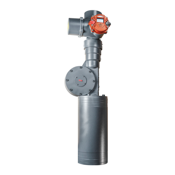
July 2016, Rev 1. Section 1: Introduction NOTE: Also refer to the operating manual for Bettis RTS FQ Fail-Safe Quarter-Turn Series electric actua- tors. Bettis RTS FQ Fail-Safe Quarter-Turn electric actuators are designed to operate appropriate fittings when a fail-safe functionality is required. -
Page 9: Section 2: Functional Description Of The Rts Fq Fail-Safe Quarter-Turn
Part Number IOM – 87376-7 July 2016, Rev 1.0 Section 2: Functional Description of the RTS FQ Fail-Safe Quarter-Turn Actuator In normal operation, the actuator is operated by a PM motor (1) via a worm gear stage (2) and a planetary gear train (3). - Page 10 User Instructions Part Number IOM – 87376-7 July 2016, Rev 1. Parts Overview: PM Motor Worm Gear Stage Planetary Gear Train Ball Screw Operating Current Brake Rack and Pinion Gear Spring Assembly End Stop Fitting Shaft This compact fail-safe actuator can be built as a version for “fail-safe open” (counter clockwise direction of rotation when looking at the fitting shaft) or “fail-safe close”...
-
Page 11: Section 3: General Information
User Instructions Part Number IOM – 87376-7 July 2016, Rev 1.0 Section 3: General Information Safety Instructions CAUTION: FOLLOW SAFETY INSTRUCTIONS When operating electrical devices, certain parts are inevitably under dangerous voltage. Work on the electrical systems or components may only be carried out by electricians or by individuals who have been instructed how to do so, working under the guidance and supervision of an electrician in accordance with electrotechnical regulations. -
Page 12: General
Use soft straps to hoist the equipment; do not attach straps to the handwheel. If the actuator is mounted on a valve, attach the hoist to the valve and not to the actuator. General The connection compartment of RTS FQ Fail-Safe Quarter-Turn actuators contains 5g of factory supplied silica gel. CAUTION: REMOVE SILICA GEL... -
Page 13: Section 5: Installation Instructions
User Instructions Part Number IOM – 87376-7 July 2016, Rev 1.0 Section 5: Installation Instructions Installation work of any kind for the actuator may only be performed by qualified personnel. Mechanical Connection Check: • Whether the fitting flange and actuator flange match-up. •... -
Page 14: Section 6: Commissioning
There is no way to operate this actuator design manually. Setting the Mechanical End Stop The RTS FQ Fail-Safe Quarter-Turn actuator only has one limited mechanical end stop that limits the travel at the fail-safe end position. The end stop is at the end of the spring cup. - Page 15 User Instructions Part Number IOM – 87376-7 July 2016, Rev 1.0 Figure 6 Mechanical End Stop (2) Parts Overview: Lock Nut End Stop Figure 7 Mechanical End Stop (3) Parts Overview: Lock Nut End Stop (hex SW70mm) Hydraulic Damper Damper Adjusting Screw Cover To adjust the end stop, first undo the locknuts.
-
Page 16: Adjusting The Hydraulic Damper (If Applicable)
User Instructions Part Number IOM – 87376-7 July 2016, Rev 1. • In fail-safe operation, let the actuator run against the stop. • Despite the locknut being undone, it must not be possible to screw the end stop further into the cover flange. NOTE: If the stroke is to be shortened by means of the end stop, the actuator must not be in the fail-safe position. -
Page 17: Section 8: Lubricant Recommendation And Requirements
The actuator has a prestressed disk spring assembly. Improper dismounting may lead to both damage to the actuator as well as serious injuries. If maintenance work is needed requiring the actuator to be dismounted, contact Emerson regarding detailed instructions and/or any special purpose tools for relaxing the spring assembly. -
Page 18: 90 O Gear Unit And Spindle Actuator
Basic Lubricant Service Interval CAUTION: CONSIDER REDUCTION FACTORS The service interval for RTS FQ Fail-Safe Quarter-Turn actuators is ten years from the shipping date. However, the functionality and service life of the lubricants depends on the operating conditions. Reduction factors have to be taken into consideration if applicable. -
Page 19: Section 9: Training
If you experience any problems during installation or in doing the adjustment work on site, please contact Emerson at phone +1 281 477 4100 to avoid any possible faulty operation or damage to the actuator. Emerson recommends only using qualified personnel to do the instal- lation. -
Page 20: Section 11: General
Reconnection during maintenance is strictly prohibited. Section 11: General The RTS FQ Fail-Safe Quarter-Turn Series are compact, rotary actuators with integrated controller for valve operation. The integral multi-turn sensor allows setting the travel up to 105 revolutions without opening the housing. -
Page 21: Operating Mode
Figure 10 Name Plate Position 11.3 Operating Mode RTS FQ Fail-Safe Quarter-Turn actuators are suitable for open-loop control (S2 operating mode - on/off duty) and closed- loop control (S4 operating mode - modulating duty) according to EN 60034-1. 11.4 Protection Class RTS FQ Fail-Safe Quarter-Turn actuators come by default with IP67 (EN 50629) protection. -
Page 22: Mounting Position
User Instructions Part Number IOM – 87376-7 July 2016, Rev 1. We recommend metallic screwed cable glands with a metrical thread. Furthermore, cable inlets not be needed must be closed with screw plugs. On explosionproof actuators cable glands with protection class EExe according EN 60079-7 must be used. After removing covers for assembly purposes or adjustment work, take special care upon reassembly so that seals are not damaged and remain properly fastened. -
Page 23: Protection Devices
User Instructions Part Number IOM – 87376-7 July 2016, Rev 1.0 Figure 12 Counterclockwise = Open CAUTION: 0BSERVE DIRECTION OF ROTATION All specifications in this operating manual refer to the standard direction of rotation. 11.7 Protection Devices 11.7.1 Torque RTS CM Compact Series actuators provide a electronic torque monitoring. Over torque can be modified in the menu of the controller for each direction separately. -
Page 24: Delivery Condition Of The Actuators
User Instructions Part Number IOM – 87376-7 July 2016, Rev 1. • Explosion Proof version: -20 C to +40 C (according to EN60079-0) • Explosion Proof version with extended temperature range: -40 C to +60 CAUTION: OBSERVE OPERATION TEMPERATURE The maximum operating temperature can also depend on further order specific components. Please refer to the technical data sheets to confirm the as-delivered product specifications. -
Page 25: Section 12: Installation Instructions
User Instructions Part Number IOM – 87376-7 July 2016, Rev 1.0 Section 12: Installation Instructions Figure 14 RTS FQ Fail-Safe Quarter-Turn Installation Parts Overview: Mounting Flange Bore Pattern G0/F10 Centering Ring Bore Pattern F07 Shaft Connection Ground Connection Installation work on any kind of actuators may only be performed by qualified personnel. -
Page 26: Mounting Position Of The Operating Unit
For output type A (unbored threaded bushing), you must sufficiently lubricate both needle bearings in the output form after processing and cleaning the spindle nut. For this purpose, use the optional RTS FQ Fail-Safe Quarter-Turn Series grease lubricant or a grease lubricant according to our... -
Page 27: Electrical Connection
9). The connection of electrical wiring must follow the circuit diagram. This can be found in the appendix of the documentation. The circuit diagram can be ordered from Emerson by specifying the serial number. When using options, such as a Profibus connection, the relevant guidelines must be followed. -
Page 28: Section 13: Setting Limits
User Instructions Part Number IOM – 87376-7 July 2016, Rev 1. Figure 19). Figure 17 Terminal Box Parts Overview: Metric Screw M40x1.5 2xM20x1.5 Terminals for the Control Signals Terminals for the Power Supply Terminal for Ground Connection Outside Ground Connection If, during outdoor installation, commissioning is not carried out immediately after electrical connection. -
Page 29: Manual Operation
Before the motorized operation of the valve, it is essential to check and eventually adjust torque settings. 13.4 End Limit Setting A detailed description of the operation of the RTS FQ Fail-Safe Quarter-Turn actuator controller can be found in Section 17.3. - Page 30 User Instructions Part Number IOM – 87376-7 July 2016, Rev 1. Scroll through the menu with the control switch. Move the control switch towards the first menu item P1.1 End limit – Open. Figure 19 Control Switch (First Menu Item) Figure 20 Display (1) Afterwards, flip up the selector switch slightly and let it snap back to its neutral position...
- Page 31 User Instructions Part Number IOM – 87376-7 July 2016, Rev 1.0 Figure 23 Selector Switch in Neutral Position (2) This changes the bottom line of the display from EDIT? to SAVE?. Figure 24 Display (2)
- Page 32 User Instructions Part Number IOM – 87376-7 July 2016, Rev 1. Figure 25 Display (3) Then, push down the selector switch until it snaps into place. In doing so, the bottom right now on the display will show "TEACHIN" Х. CAUTION: USE APPROPRIATE SWITCH Once the display shows "TEACHIN", use the operating switch (black switch) to start the motorized operation of the actuator.
- Page 33 User Instructions Part Number IOM – 87376-7 July 2016, Rev 1.0 Figure 26 Selector Switch Flipped Down Figure 27 Display (4) Manually move the actuator with the handwheel (see Section 13.1 Section 13.6) or by motor via the operating switch (black button) to the end position OPEN of the valve. •...
- Page 34 User Instructions Part Number IOM – 87376-7 July 2016, Rev 1. Display Overview: Absolute value Relative Value When the desired end position OPEN of the valve is reached, move the selector switch back to the middle position. Thus, the line "TEACHIN" disappears. Figure 29 Selector Switch in Neutral Position (4) Figure 30...
- Page 35 User Instructions Part Number IOM – 87376-7 July 2016, Rev 1.0 Figure 32 Selector Switch Flipped Up (2) Figure 33 Selector Switch in Neutral Position (6)
- Page 36 Adjustment of Fail-Safe Speed Mounting of Linear Fail-Safe Actuator RTS FQ Series ctuators move the stem of valve to the fail-safe position in case of fail-safe event. In general stem of actuator is at fail-safe position at delivery! Depending on valve has to be closed or opened by force (sealing force is required in fail- safe...
- Page 37 User Instructions Part Number IOM – 87376-7 July 2016, Rev 1.0 • Connect mounting kit to valve and fix according valve producer specification • Be sure stem of valve is exact in desired fail-safe end position • Be sure stem of actuator is in fail-safe position. Actuator must not be electrically connected! Hand wheel must not be engaged.
-
Page 38: Section 15: Control Unit
User Instructions Part Number IOM – 87376-7 July 2016, Rev 1. • Connect mounting kit to valve and fix according valve producer specification • Be sure stem of valve is exact in desired fail-safe end position • Stem of actuator has to be moved 2 – 5 mm away from fail-safe position by using hand wheel (if applicable, refer to 6.2 manual operation)! If actuator is not equipped with hand wheel switch to alternative procedure: •... -
Page 39: Display Elements
User Instructions Part Number IOM – 87376-7 July 2016, Rev 1.0 Figure 36 Selector/Control Switch Operating Unit Parts Overview: Selector Switch Control Switch Graphic Display LED Display The controller switches serve on the one hand for electric motor operation of the actuator and, on the other hand, to configure and view various menu items. -
Page 40: Operation
User Instructions Part Number IOM – 87376-7 July 2016, Rev 1. 15.3 Operation The actuator is operated via the switches located on the controller (selection and control switch). All actuator settings can be entered with these switches. Furthermore, configuration is also possible via the IR interface or the Bluetooth Interface (see Section 20). - Page 41 User Instructions Part Number IOM – 87376-7 July 2016, Rev 1.0 Figure 42 Halfway Switch Flip (it will jump to the next parameter category) Figure 43 Full Switch Flip (it will jump to the end of the menu) 15.3.1 Operation Mode Use the selector switch (red) to determine the various operating states of the actuator.
- Page 42 User Instructions Part Number IOM – 87376-7 July 2016, Rev 1. Depending on the selector switch position, the control switch performs different functions: Table 6. Selector Switch Position Table The control switch is used to scroll up or down the menu according to internal symbolism.
- Page 43 User Instructions Part Number IOM – 87376-7 July 2016, Rev 1.0 Figure 45 Display (12) Use the control switch towards to the characters to change the parameter (see Figure Figure 45). After reaching the desired parameter value, confirm the value with the selector switch again, flip it slightly towards , (see Figure 33...
- Page 44 User Instructions Part Number IOM – 87376-7 July 2016, Rev 1. Figure 48 Display (13) Afterwards, flip up slightly the selector switch towards and let it snap back to its neutral position. Figure 49 Selector Switch in Neutral Position (7)
- Page 45 User Instructions Part Number IOM – 87376-7 July 2016, Rev 1.0 Figure 50 Selector Switch Flipped Up (3) Figure 51 Selector Switch in Neutral Position (8) This changes the bottom line of the display from "EDIT?" to "SAVE?". Figure 52 Display (14)
- Page 46 User Instructions Part Number IOM – 87376-7 July 2016, Rev 1. Figure 53 Display (15) Thereafter, flip up the control switch toward to change the value from 0 (off ) to 2 (Bluetooth). Figure 54 Control Switch Flipped Up Figure 55 Display (16)
- Page 47 User Instructions Part Number IOM – 87376-7 July 2016, Rev 1.0 If the value changes to 1, confirm the selection by flipping halfway up the selector switch towards and letting it snap back to its neutral position (see Figure 51 Figure 53).
-
Page 48: Section 16: Parameter Menu
User Instructions Part Number IOM – 87376-7 July 2016, Rev 1. Figure 58 Display (18) CAUTION: MAX. TORQUE MUST BE ALREADY SET Please note that, during motor operation, only torque monitoring remains active, as travel adjustment will happen subsequently. Therefore, please check beforehand whether the maximum torque has been already set. - Page 49 The crossing of all signals and commands is performed by the controller. Rotate sense P1.6 End limit No function at RTS FQ Fail-Safe Quarter-Turn Series. position Close = green (0) Definition of the LED colour of the CLOSED or OPEN end P1.7 End limit LED function position signalization.
-
Page 50: Parameter Group: Torque
P2.1 and P2.2, and to prevent an erroneous increase above the allowed value of these two parameters. P2.4 Torque Latching {Off (0)} Unassigned in RTS FQ Fail-Safe Quarter-Turn Series P2.5 Torque Boost Open {0%} Unassigned in RTS FQ Fail-Safe Quarter-Turn Series P2.6... -
Page 51: Parameter Group: Ramp (Option)
User Instructions Part Number IOM – 87376-7 July 2016, Rev 1.0 Seal-tight speed. Speed at which the actuator runs Torque- P4.7 Speed 2.5 - 72.2min near the end position at torque-dependent switch dependent off (see P1.3 and P1.4) P4.8 Speed Minimum 2.5 - 72.2min Minimum speed... -
Page 52: Parameter Group: Position
User Instructions Part Number IOM – 87376-7 July 2016, Rev 1. Table 12. Password Table Menu Sub Menu Poss. Notes/Comments Item Item Setting Status display and history data are still viewable; access to the parameter menu is locked until this Reading P7.1 Password... -
Page 53: Parameter Group: Binary Inputs
User Instructions Part Number IOM – 87376-7 July 2016, Rev 1.0 16.8 Parameter Group: Binary Inputs The controller is equipped with 5 freely configurable binary inputs. Please find further information on technical data of the binary inputs in Section 33.1. Binary inputs are also effective during actuator control via Profibus (option). - Page 54 User Instructions Part Number IOM – 87376-7 July 2016, Rev 1. Table 14. Binary Inputs Table Menu Sub Menu Poss. Setting Notes/Comments Item Item P9.1 Binary Input 1 0: No This input has no function Input Function OPEN command in REMOTE mode (selector 1: Open switch in position REMOTE).
- Page 55 User Instructions Part Number IOM – 87376-7 July 2016, Rev 1.0 Menu Sub Menu Poss. Setting Notes/Comments Item Item With activated (switched) signal, the actuator is 19: Block locked for operation also in local mode. 20: Contoller Positioner lock lock 21: Release The actuator may be operated only with a Local...
-
Page 56: Parameter Group: Binary Outputs
User Instructions Part Number IOM – 87376-7 July 2016, Rev 1. Menu Sub Menu Poss. Setting Notes/Comments Item Item Intermediate As Intermediate position 1 but active low position 1 inv. Intermediate As Intermediate position 2 but active low position 2 inv. Intermediate As Intermediate position 3 but active low position 3 inv. - Page 57 User Instructions Part Number IOM – 87376-7 July 2016, Rev 1.0 Table 15. Binary Outputs Table Menu Sub Menu Poss. Setting Notes/Comments Item Item P10.1 Binary Output 1 0: User Optional Output Defined 1: Ready Actuator is ready 2: Fault General fault;...
- Page 58 User Instructions Part Number IOM – 87376-7 July 2016, Rev 1. Menu Sub Menu Poss. Setting Notes/Comments Item Item 28: Binary Forwarding of binary input to output Input 1 29: Binary Forwarding of binary input to output Input 2 30: Binary Forwarding of binary input to output Input 3 31: Binary...
- Page 59 User Instructions Part Number IOM – 87376-7 July 2016, Rev 1.0 Menu Sub Menu Poss. Setting Notes/Comments Item Item 49: Position = Position = Intermediate position 4. The width of Int. 4 the interval is set with the parameter P8.6. 50: Position Position = emergency position.
-
Page 60: Parameter Group: Position Output (Option)
User Instructions Part Number IOM – 87376-7 July 2016, Rev 1. Binary Output 7 See Output 1 P10.14 Output Configuration Configuration Binary P10.15 Output 8 See Output 1 Output Binary Output 8 See Output 1 P10.16 Output Configuration Configuration CAUTION: OBSERVE TORQUE POSITION When using the point torque-dependent OPEN or torque-dependent CLOSED (see Section 18.1, Menu P1.3 and P1.4) the actuator will only be open or closed when the set torque and the... - Page 61 User Instructions Part Number IOM – 87376-7 July 2016, Rev 1.0 Table 17. Step Mode Table Menu Sub Menu Poss. Setting Notes/Comments Item Item Disabled Step mode operation is disabled Step mode operation is enabled in LOCAL, Enabled REMOTE and EMERGENCY operation. Step Mode Local only Step mode mode is only enabled in LOCAL mode...
-
Page 62: Parameter Group: Positioner (Option)
User Instructions Part Number IOM – 87376-7 July 2016, Rev 1. 16.12 Parameter Group: Positioner (Option) The positioner SR option is used to control the electric actuator by means of a set point input 0/4-20 mA signal. The SR helps control the position of the actuator, i.e., the positioner ensures that the actual value and thus the position of the actuator matches the desired set point. - Page 63 (restless loop, small dead zone, clocking near to the target value), we therefore recommend electronic reversing contactor. Variable speed actuators (RTS FQ Fail-Safe Quarter- Turn Series and Smartcon CSC FU): Without function Fixed speed actuators (Smartcon CSC): P13.10...
-
Page 64: Parameter Group: Controller (Optional)
User Instructions Part Number IOM – 87376-7 July 2016, Rev 1. Figure 60 Assigning the Position to the Setpoint 16.13 Parameter Group: Controller (Optional) The optional PID controller is used for controlling an external actual value (process variable) to a setpoint using 0/4-20 mA signal by readjusting the actuator. - Page 65 User Instructions Part Number IOM – 87376-7 July 2016, Rev 1.0 Menu Sub Menu Poss. Setting Notes/Comments Item Item P14.6 Gain (P) +50 - 50, Gain (proportional value) of the PID controller contoller The shorter the reset time (integral time, integral value), the stronger is the effect of the integral P14.7 Reset time (I)
-
Page 66: Parameter Group: Characteristic Curves (Optional)
User Instructions Part Number IOM – 87376-7 July 2016, Rev 1. Calibration Calibration process: By applying 20mA to the of External P14.13 -10.– 10% external actual value input, this parameter is controller Actual corrected until the readout matches to 20mA. Value 16.14 Parameter Group: Characteristic Curves... -
Page 67: Parameter Group: Identification (Option)
User Instructions Part Number IOM – 87376-7 July 2016, Rev 1.0 The torque characteristic curve is disabled for the CLOSED direction. The torque characteristic curve is enabled for the Torque P17.2 Characteristic CLOSED direction. Closed The torque characteristic curve is enabled for the Local + CLOSED direction only in LOCAL and REMOTE Remote only... -
Page 68: Section 17: Status Area
User Instructions Part Number IOM – 87376-7 July 2016, Rev 1. Customer Actuator parameters, excluding points P1.1 Configuration to P1.6 will be overwritten with customer parameters. Customer Actuator parameters, including points P1.1 Configuration to P1.6 will be overwritten with customer Load P20.3 Miscellaneous parameters. - Page 69 User Instructions Part Number IOM – 87376-7 July 2016, Rev 1.0 Display Overview: Ouput Number Signal (0=LOW; 1=HIGH) 17.1.2 Status - Binary Inputs Display of binary inputs: A set input is represented by 1. Figure 63 Binary Inputs Display Display Overview: Input Number Signal (0=LOW: 1=HIGH) 17.1.3...
- Page 70 July 2016, Rev 1. Input 1 Input 2 Ouput All values in mA 17.1.4 Stauts - Absolute Values This point is not relevant for RTS FQ Fail-Safe Quarter-Turn Series. 17.1.5 Status - Firmware Figure 65 Firmware Display Display Overview: Firmware Firmware Date 17.1.6...
-
Page 71: History
User Instructions Part Number IOM – 87376-7 July 2016, Rev 1.0 Serial Number of the Actuator Serial Number of Electronics 17.1.7 Status - Meter Readings Figure 67 Counter Values Display Display Overview: Power-on Cycles Operating Hours Engine Duration 17.2 History History shows the last 20 events/entries. -
Page 72: Section 18: Infrared Connection
User Instructions Part Number IOM – 87376-7 July 2016, Rev 1. During operation, it must be ensured that the IR interface surface is protected from strong disturbances which may otherwise compromise the communication. Before mounting the infrared adapter, clean the surface of the infrared interface with a damp cloth. When the infrared interface is enabled, it is indicated by Light Emitting Diode L5 (see Figure 70).The infrared interface can be enabled in the menu item P20.6. -
Page 73: Section 21: Troubleshooting
User Instructions Part Number IOM – 87376-7 July 2016, Rev 1.0 On-going monitoring: • Beware of increased running noise. During long downtime periods, operate the actuator at least every 3 months. • For actuators with output types A, B and C according to DIN 3210-A, B1, B2 and C according to DIN ISO 5210, relubricate at least every 6 months on existing grease fittings (see Section... -
Page 74: Main Body
User Instructions Part Number IOM – 87376-7 July 2016, Rev 1. Figure 69 Logic Board of Controller Parts Overview: Fuse F10a for the Binary Outputs Fuse F10b for Auxillary Table 24. Fuses on the Logic Board Fuse Value Manufacturer F10a Littelfuse 454 NANO Slo-Blo träge... -
Page 75: Basic Lubricant Service Interval
23.3 Basic Lubricant Service Interval RTS FQ Fail-Safe Quarter-Turn Series actuators must be serviced 10 years after delivery by Emerson. The functionality and durability of the lubricant is however contingent upon the operating conditions. Where appropriate, reduction factors must be considered. -
Page 76: Section 24: Training
If you experience problems during installation or upon adjustments on site, please contact Emerson, Texas at +1 281 477 4100 or to prevent any operational errors or damage to the actuators. Emerson recommends engaging only qualified personnel for installation of RTS CM Comapct Series actuators. - Page 77 User Instructions Part Number IOM – 87376-7 July 2016, Rev 1.0 IP66/67 TÜV Austria • EN 60529-1:1991 + A1:2000 Functional Safety FMEDA • IEC 61508:2010 • SIL 1 (single device) • SIL 2 (redundant configuration)
- Page 78 User Instructions Part Number IOM – 87376-7 July 2016, Rev 1. RTS FQ TYPE FQ-03 FQ-06 FQ-20 Max Electric Torque max. lbs. ft (Nm) 220 (300) 440 (600) 1,475 (2,000) Max Fail-safe Torque max. lbs. ft (Nm) 110 (150) 220 (300)
-
Page 79: Section 26: Technical Data General
User Instructions Part Number IOM – 87376-7 July 2016, Rev 1.0 Section 26: Technical Data General 26.1 Binary Inputs Table 26. Input Data Table Parameter Value Count 24VDC/48VDC Nominal voltage towards common ground Threshold voltage for input set >15V Threshold voltage for input not set <10V Maximum voltage 60VDC... - Page 80 User Instructions Part Number IOM – 87376-7 July 2016, Rev 1. Figure 72 Logic Board Jumpers JP1 to JP3 can be used to interconnect the binary inputs to groups with separate earths: Figure 73 5 Inputs with Same Common Figure 74 2 Separated Groups of 2 Inputs with Same Ground...
- Page 81 User Instructions Part Number IOM – 87376-7 July 2016, Rev 1.0 Input In3 is disabled. Figure 75 3 Separated Inputs Inputs In2 and In4 are disabled. Figure 76 3 Inputs with Same Common Ground and 1 Separated Input Input In4 disabled.
-
Page 82: Binary Outputs
User Instructions Part Number IOM – 87376-7 July 2016, Rev 1. Figure 77 1 Separated Input and 3 Inputs with Same Common Input In2 is disabled. 26.2 Binary Outputs Table 27. Output Data Table Parameter Value Count Power supply 24VDC nominal 11 to 35VDC Range (either from internal or external) -
Page 83: Analog Outputs
User Instructions Part Number IOM – 87376-7 July 2016, Rev 1.0 Only in conjunction with the PID controller. Table 29. Analog Input 2 Table Parameter Value Current range 0-20, 8mA Resolution 10-bit Accuracy 0.5% Input resistance 120 Ohm Jumper JP6 can be used to switch Analog Input 2 from a passive input (default) to an input with 24-V power supply (for 4-20 mA, two-wire transmitters). -
Page 84: Connections For Non-Explosion Proof Version
User Instructions Part Number IOM – 87376-7 July 2016, Rev 1. The power-save mode is defined as follows: • No power supply (the controller is powered exclusively through the 24V auxiliary voltage input). • The lighting of the LCD display switches off automatically. •... -
Page 85: Appendix A: List Of Figures
July 2016, Rev 1.0 Appendix A: List of Figures Figure 1 RTS FQ Fail-Safe Quarter-Turn Series ....................1 Figure 2 Cut-out of the RTS FQ Fail-Safe Quarter-Turn Series ..............2 Figure 3 Fail-safe Open Version ...........................3 Figure 4 Fail-safe Close Version ...........................3 Figure 5 Mechanical End Stop (1) ........................ - Page 86 User Instructions Part Number IOM – 87376-7 July 2016, Rev 1. Figure 27 Display (3) ............................... 36 Figure 28 Selector Switch Flipped Down ......................37 Figure 29 Display (4) ............................... 37 Figure 30 Display (5) ............................... 38 Figure 31 Selector Switch in Neutral Position (3) ..................38 Figure 32 Display (6) ...............................
-
Page 87: Appendix B: List Of Tables
User Instructions Part Number IOM – 87376-7 July 2016, Rev 1.0 Figure 70 Infrared Connection ..........................78 Figure 71 Logic Board of Controller ........................82 Figure 72 Current/Voltage Relation ........................93 Figure 73 Control Unit ............................93 Figure 74 Logic Board ............................94 Figure 75 5 Inputs with Same Common ...................... - Page 88 User Instructions Part Number IOM – 87376-7 July 2016, Rev 1. Table 26. Output Data - Standard Version Table ..................90 Table 27. Output Data - 24VDC Version Table ....................90 Table 28. Power Supply - Power Electronics - Standard Version Table..........91 Table 29.
- Page 89 User Instructions Part Number IOM – 87376-7 July 2016, Rev 1.0...
- Page 90 ©2016 Emerson Process Management. All rights reserved. F +65 6268 0028 F +27 11 451 3800 The Emerson logo is a trademark and service mark of Emerson No.1 Lai Yuan Road EUROPE Electric Co. All other marks are property of their respective Wuqing Development Area owners.
Need help?
Do you have a question about the RTS FQ and is the answer not in the manual?
Questions and answers