Table of Contents
Advertisement
Advertisement
Table of Contents

Related Manuals for Digital Watchdog DWC-PB6M4T


Summary of Contents for Digital Watchdog DWC-PB6M4T
- Page 1 User’s Manual l...
-
Page 5: Product And Accessories
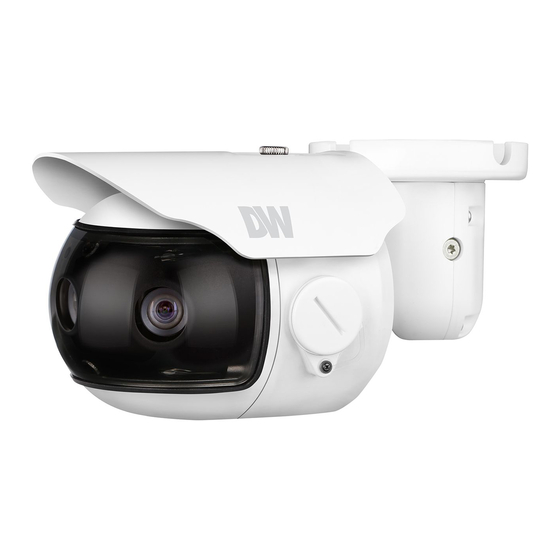
Introduction - Product & Accessories Please check if all the camera and accessories are included in the package. Cables Camera Sunshield Screws Quick Manual Template Sheet T-Wrench Screw & Plastic Anchor-4pcs Sunshield... - Page 6 Introduction - Part Sunshield Cables Ball Neck Bracket Pan/Tilt Stoper Screw Con Cap Lens...
-
Page 7: Installation
Installation - Installation Before installing your camera, you have to read the following cautions. Reset SD Card Slot ass cables through Reset to the Factory Default Press the reset button for 5 seconds to return the setup to the factory default. Connect the network cable, power cable respectively. -
Page 8: Inserting/Removing An Sd Memory Card
Installation - Inserting/Removing an SD Memory Card The memory card is an external data storage device that has been developed to offer an entirely new way to record and share video, audio, and text data using digital devices. Recommended SD Card Specification (Not Included) - Type: Micro SD (SDHC) - Manufacturer: Transcend, Kingston, Toshiba, Sanddisk... - Page 9 Installation - Cabling Two Options Use a PoE-enabled switch to connect data and power through a single cable and begin viewing and recording images instantly. A non-PoE switch will require an adaptor for power transmission. 1. Using a PoE-Enabled Switch 2.
- Page 10 Installation - Cabling Alarm Input Alarm Output IR SUNSHIELD Audio Input Audio Output Network Power Power Connection Audio Output Please, check the voltage and current capacity of rated power Connect the ‘Audio Out’ cable of the camera to device like carefully.
-
Page 12: Network Setup
Network Setup - Quick Start of Network Connection Please follow the steps below to complete Access your IP Camera via the Internet : the initial setup of the network function. If you use a static IP address assigned by your ISP 1) Open Internet Explorer. -
Page 13: Ddns Registration
Network Setup - DDNS Registration If you have DYNAMIC IP service from your Internet Service Provider (ISP), you can’t tell the current IP address of the IP Camera. To solve this problem, you have to register to our DDNS service. t, you have to check if you are using dynamic addressing. -
Page 14: Guide To Network Environment
Network Setup - Guide to Network Environment Please configure the IP Camera at the 5. The following descriptions are several basic network scenarios. Determine which scenario describes your network. installation site. You must determine your If your network does not match one of the scenarios below network scenario in order to configure the IP and you are unsure how to setup your IP Camera, contact Camera with the proper TCP/IP settings. - Page 15 Network Setup - Setup Case A, B Case A: as follows : Dynamic IP + Personal Router [Most SOHO] Network Type : STATIC (even though you have Dynamic IP from your ISP, use STATIC on the IP Camera) Camera Internet Address : A private IP address such as 192.168.0.200 (Example) You need to assign an IP address to the IP Camera just as you do...
- Page 16 Network Setup - Setup Case C, D Case C: Case D: Static(Fixed) IP [Dedicated line directly Dynamic IP + DSL/Cable Modem [Connected to the IP Camera] directly to the IP Camera] Camera Camera Phone Line or CATV Cable/xDSL Modem (ISP Provided) Public Line Gateway or Router at ISP...
-
Page 17: Port Forwarding
Network Setup - Port Forwarding After entering the correct TCP/IP settings, you are ready for ‘Port Forwarding’(Cases A, B). Please record the TCP/IP settings of your IP Camera for future reference. You may need this information to access your IP IP Camera TCP/IP Settings IP Address Subnet Mask... - Page 18 Network Setup - Starting IP Camera After forwarding correctly the Web Port, through your router (if applicable), install the IP Camera in a proper location. Locate the serial number located on the label attached to the bottom of the IP Camera, you will need this for DDNS registration.
- Page 19 Webviewer - Settings Login Administrator connection (on the initial page) 1) “ID” admin (Unchangeable) 2) “Password” admin (the default password can be changed in the web setting page. 3) Type the ID and password and click the button “Login”, the web monitoring page shows up. 4) You can also type the ID and password and click “Login”...
-
Page 20: Web Viewer
Webviewer - Settings Web viewer Monitor and configure the MEGApix® PANO™ camera through a built-in web viewer. Type the camera’s IP address in a web browser. Enter Username and Password.Default: Username: admin | Password: admin The web browser may ask to install ActiveX to view video from the camera. - Page 21 Webviewer - Settings Web viewer Monitor and configure the MEGApix® PANO™ camera through a built-in web viewer. Setting button Audio On/Off enables you to move to the web setting page (Live button: enables you to monitor the audio signal of the microphone Web setting page ->...
- Page 22 Webviewer - Settings Status View the camera’s basic settings and status. Network Status Displays the camera’s current network information, including MAC Address, IP Address, Subnet Mask, Gateway, Default DNS, IPv4, Received Data velocity, Transmitted Data celocity, and the connection status for Link Speed/Duplex Mode.
- Page 23 Webviewer - Settings Network View the camera’s network information. IP Address IPv6 Network Setting 1. Dynamic IP - Select Dynamic IP if you are using a DHCP Disabled by default. Server. The camera will obtain all its network information 1. Manually set the camera’s IP address and gateway. automatically from the server.
- Page 24 Webviewer - Settings Panorama Camera Setup Set the camera’s common options. BW/Color/Auto NTSC/PAL Auto : The camera will switch between color and BW based The camera will switch between NTSC and PAL. on the AGC levels. NTSC 60Hz / PAL 50Hz. BW : The camera will remain in BW mode regardless of the lighting environment.
-
Page 25: Motion Detection
Webviewer - Settings Motion Detection To setup a motion detection mask on the camera’s view, click on any point in the camera’s preview and drag to make a detection range. nce a motion detection mask is set, a red mark will appear on the upper bar of the video image on the web monitoring page. - Page 26 Webviewer - Settings Add OSD text or a logo to the camera’s view. OSD : : Text OSD : : Text Date / Time / Camera Name Enable Enable check the box next to the information you want to show on Check for the activation.
-
Page 27: Video Profile
Webviewer - Settings Video Profile Streams Frame Per Sec Select which stream to show in the preview and adjust in The number of frames transferred in a second (default: 20). the settings of this page. The camera supports two simult- aneous stream plus a JPEG stream. - Page 28 Webviewer - Settings Video Profile H.264 Reference Frames (Skipping Modes) Enable Once the value is set to "4X", the camera will play recorded Capture the camera’s view as JPEG. video at "4X" with less system resources. Resolution Capture Mode Adjust the resolution. In case the resolution of the monitor is SD (Standard Defi- nition), the HD (High Definition) video ratio (16:9) will be Quality...
-
Page 29: Audio Profile
Webviewer - Settings Audio Profile Audio Option : : Input Audio Option : : Output Input Type Audio Codec Line ( or line / mic ; the models with built-in mic) G.711-u / G.711-a / G.726 (quality : G.711>G.726, playing compatibility : G.711<G.726) Audio Codec G.711-u / G.711-a / G.726 (quality : G.711>G.726, playing... -
Page 30: Streaming Setting
Webviewer - Settings Streaming Setting Proprietary TCP Port The port for the transmission by the proprietary protocol (based on the settings under “Video Profile / Video Setting / Proprietary Stream Port ”). Connection Lists The IP address and port information of the monitoring de- vices that are connected to the camera. - Page 31 Webviewer - Settings Streaming Setting Adjust the camera’s streams and their advanced settings such as RTSP, TCP and Multi-cast. Video Address User RTSP Authentication The IP address for video data transmission. Check the box if an authentication process is required. Video Port Use RTCP The port number for video data transmission.
- Page 32 Webviewer - Settings Events [Action Types] Digital Input Logical Status (Sensor Type) Preset Move Set according to the normal state of the electrical signal of When the PTZ Camera is connected to, the command the attached device. (Open / Close) “Preset Move”...
- Page 33 Webviewer - Settings Events [Event Types] Add Event (+) button Click this button to add an event entry. 1) Event Type : Select one out of “Digital Input / Motion / Timer” 1-1) Digital Input > Sensor : Select a sensor to use. Digital Input >...
-
Page 34: Local Storage
Webviewer - Settings Local Storage The camera supports SD/SDHC memory card for local recording. Overwrite Select Stream Select whether to overwrite old data when the card is full. Select which stream to record. Select Storage Click OK to apply any changes to the settings. This section shows the SD Card used for storage. - Page 35 Webviewer - Settings Date/Time Use this menu to adjust the camera’s local date, time, and time server settings. Date/Time Enable Displays the current time. Check the box to enable. New Date/Time (Manual) Interval Adjust the camera’s time manually. Click the “Set” button Set the request time intervals (in minutes).
- Page 36 Webviewer - Settings UPnP The camera supports UPnP for auto detection with Windows explorer. Enable Check to enable UPnP. Friendly name This is the name identifying the camera when using the UPnP search It is created by the camera’s MAC address. You can modify it as needed.
- Page 37 Webviewer - Settings Bonjour The camera supports Bonjour for auto detection with Windows explorer. Enable Check to enable UPnP. Friendly name This is the name identifying the camera when using the UPnP search. It is created by the camera’s MAC address. You can modify it as needed.
- Page 38 Webviewer - Settings SNMP Use this menu to set the camera’s SNMP settings. Enable Check to enable. Read community Shows the running mode as “public”. (fixed) UDP Port Enter the port number for use. Click OK to apply any changes to the settings.
- Page 39 Webviewer - Settings Port Use this menu to Set up the port number for the data communication. Web (HTTP) The camera’s web port is set by default to 80. You can modify it as needed. Serial Port #1(RS485) (Currently not supported) Serial Port #2(RS232) (Currently not supported) Click OK to apply any changes to the settings.
- Page 40 Webviewer - Settings Security This menu allows you to restrict access to the camera according to IP addresses. Enable Check to enable. Basic Policy Select “allow” / “deny” IP Addresses Lisk Create the IP address list for filtering. Press the ‘Add’ button to add new IP addresses to the list, or ‘delete’...
- Page 41 Webviewer - Settings DDNS The camera supports a Dynamic DNS feature. Please note that these are third-part DDNS services, and some may require subscription or payment. Enable Check to enable. Select Service Select a service to use. Type the information that is used on the registration pro- cess of the DDNS server homepage.
- Page 42 Webviewer - Settings Account The camera supports multiple users with different permission levels. Admin Password Enter the administrator’s password. Enter or modify the ID for the user. New Password, Confirm Password Enter or modify the password for the ID to be added. Apply/Cancel button Click “Apply”...
-
Page 43: Firmware Update
Webviewer - Settings Firmware Update Use this menu to update the camera’s firmware when needed. Current Firmware Version Displays the current firmware version. Firmware File 1) Click “Browse...” and select the file to upload. 2) Click “Upload” to start updating. 3) The camera’s power supply must not be interrupted. -
Page 44: Factory Default
Webviewer - Settings Factory Default When necessary, you can reset the camera to its factory default. Reset button Click the button to initialize the reset of the selected values. Please note to click the reset button only afterselecting the values to be initialized. Show only changed values check box Check to display only the changed values (default). - Page 45 Webviewer - Settings Report This page displays the camera’s current setting and can be printed or saved as a PDF file for reference. Use the “Print” button to export the report for you records.
- Page 46 Webviewer - Settings Open Source Info. This page documents the camera’s firmware and web client information for open source integrations.
- Page 47 Webviewer - Settings Reboot You can select to reboot the camera as needed. A confirmation window will appear to confirm the reboot.
- Page 48 Appendix A : Current TCP/IP Settings If your IP settings are obtained automatically, you could use the MS-DOS prompt (or Command Prompt) to determine your IP address. For information on how to do this, please read the FAQ. 1. Windows 2000 or XP Users 2.
- Page 49 Appendix - B : Changing IP address and subnet mask 1. Windows 2000 or XP Users 2. Windows Vista or 7 Users Start Start Control Panel Control Panel Network and Network and Dial-up sharing center Connection or Network Connection Manage network connections Right-click Local Area Connection...
-
Page 50: C : Port Forwarding
Appendix - C : Port Forwarding After assigning the IP Camera a web server For Linksys BEFSR41 Cable/DSL routers: port and video server port you must use Port 1) Open a web browser and type http://192.168.1.1 into you Forwarding. (for cases A, B) Address bar. - Page 51 Appendix - C : Port Forwarding For Netgear RP614 routers: 1) Input http://192.168.0.1 in address bar of web browser. http://192.168.0.1 is the default IP address. 2) If it asks ID and password, input admin as ID and password as password. 3) Click “Port Forwarding”...
- Page 52 Appendix - My POWER light is not on? How do I “PING” an IP address? Power is not being supplied to the unit. Please use the power 1) Open an MS-DOS (or Command) prompt supply shipped with the unit and verify that a power source 2) At the prompt type - “ping xxx.xxx.xxx.xxx”...
-
Page 53: Specifications
Specifications - Dimension Unit: mm 250 ~ 270 96.5 144.5...
Need help?
Do you have a question about the DWC-PB6M4T and is the answer not in the manual?
Questions and answers