Table of Contents
Advertisement
Quick Links
Advertisement
Table of Contents

Related Manuals for Digital Watchdog MEGApix DWC-MPTZ336XW


Summary of Contents for Digital Watchdog MEGApix DWC-MPTZ336XW
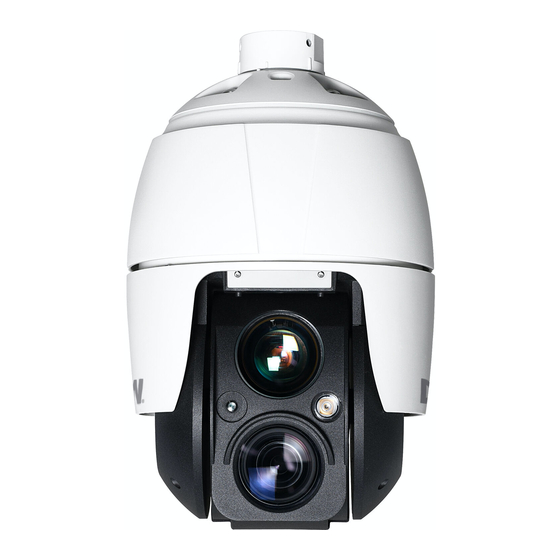
- Page 1 3MP PTZ IP Camera PTZ336XW User’s Manual 04/20...
-
Page 4: Table Of Contents
Contents 1 Introduction ..........................5 1.1 Components ............................5 2 Installation .............................. 6 2.1 Preparing the camera ........................6 2.1.1 Mounting the camera ....................... 7 2.2 Cabling the camera ........................8 Connections ..........................10 2.4 Resetting the camera to default settings................10 3 Web viewer .............................. -
Page 5: Introduction
1 Introduction The camera supports the network service for a sensor image with a progressive scan, which can be monitored on a real-time screen regardless of distances and locations. By using its dedicated program, many users can have access to the camera at once or a single user can monitor various cameras at the same time. -
Page 6: Installation
2 Installation 2.1 Preparing the camera A mounting accessory is required to complete the installation and is sold separately. The wall or ceiling mount must be attached to a structural object such as hardwood, concrete that will support the weight of the mount and dome camera. 1. -
Page 7: Mounting The Camera
2.1.1 Mounting the camera The wall mounting plate must be attached to a structural object such as concrete that will support the weight of the mount and dome camera. 1. Using the mounting template or the mounting accessory itself, mark and drill the necessary holes in the mounting surface. -
Page 8: Cabling The Camera
2.2 Cabling the camera Follow the table and diagram below to connect your camera to all external devices. Connector Wire Color Description Camera power Power jack Black (12vdc) RJ-45 Black Ethernet RCA jack Black Audio input RCA jack Gray Audio output Yellow Alarm input 1 White... - Page 9 You can use external d evices to signal the camera to react to events. Mechanical or electrical switches can be wired to the A1, A2, A3, A4 (Alarm Input 1, 2, 3, 4) and G (Ground) connectors. NOTE: All the connectors marked G or GND is common. Connect the ground sid e of the alarm input and/or alarm output to the G (Ground) connector.
-
Page 10: Connections
Connections SD card insertion Users can insert and remove an SD card as shown in the following picture. 1. Open the SD card cover under the camera’s lens. 2. Insert or remove the SD card as needed. 3. Tightly close the SD card cover to ensure it is waterproof. 2.4 Resetting the camera to default settings To reset the camera to its original factory settings, open the camera’s web viewer and go to the Setup >... - Page 11 Using the reset button: Follow the instructions below to reset the camera to the factory default settings using the Reset button. 1. Switch off the camera by disconnecting the power adapter. 2. Open the SD card cover. 3. Press and hold the reset button on the board with your finger while reconnecting the power.
-
Page 12: Web Viewer
3 Web viewer The camera can be used with the Windows® operating system and browsers. The recommended browsers are Internet Explorer, Safari, Firefox, Opera and Google Chrome with Windows. NOTE: To view streaming vid eo in Microsoft Internet Explorer, set your browser to allow ActiveX controls. -
Page 13: Access From The Internet
3.2 Access from the Internet Once connected, the camera is accessible on your local network (LAN). To access the camera from the Internet you must configure your broadband router to allow incoming data traffic to the camera. To do this, enable the NAT traversal feature, which will attempt to automatically configure the router to allow access to the camera. -
Page 14: Live View Page
3.4 Live View Page The Live View page comes in several screen mod es. Users are allowed to select the most suitable one out of those mod es. Ad just the mod e following your PC specifications and monitoring purposes. 1. - Page 15 2. Control toolbar The live viewer toolbar is available in the web browser page only. It displays the following buttons: The Stop button stops the video stream being played. Pressing the key again toggles the play and stop. The Play button connects to the camera or starts playing a video stream. The Pause button pauses the video stream being played.
-
Page 16: Playback
3.5 Playback The Playback window contains a list of recordings made to the memory card. It shows each recording’s start time, length, the event type used to start the recording, calendar and time- slice bar indicates if the recording exists or not. The description of the playback window follows. - Page 17 Display an hour-based search screen for the chosen date. If there is recording data, a blue section will be displayed on a 24-hour basis. If you select a specific hour in the chart, a yellow square on the hour will be displayed. 4.
-
Page 18: Camera Setup
3.6 Camera Setup This section describes how to configure the camera. The ad ministrator has unrestricted access to all the Setup tools, whereas Operators have access to the settings of Basic Configuration, which are Live View, Video and Image, Audio, Event, Dome Configuration, and System. - Page 19 Users User access control is enabled by default. The administrator can set up other users, by giving user names and passwords. It is also possible to allow anonymous viewer login, which means that anybody may access the Live View page, as described below: The user list displays the authorized users and user groups (levels): User Group Authority...
- Page 20 Network The camera supports both IP version 4 and IP version 6. Both versions may be enabled simultaneously, and at least one version must always be enabled. When using IPv4, the IP address for the camera can be set automatically via DHCP, or a static IP address can be set manually.
- Page 21 Video and Image Users can setup and change the setting of an individual video stream on this page. Please refer to “Video and Image > Basic” for more details about Video and Image setup.
- Page 22 Audio The camera can transmit audio to other clients using an external microphone and can play audio received from other clients by attaching a speaker. Users can setup and change the setting of Audio on this page. Please refer to “Audio” for more details about the Audio setup. Date and Time Users can set time directly or assign a time server to get the current time, as well as determine Date and Time format on this page.
-
Page 23: Video And Image
3.6.2 Video and Image Basic Sensor Setting: • Capture mode: User can select sensor capture mode between NTSC and PAL (Some models are fixed to NTSC or PAL). Stream 1 Setting: • Codec: The codec supported in Stream 1 is H.264 and H.265. There are 3 pre-programmed stream profiles available for quick set-up. - Page 24 when the High Profile was developed for those applications. • Resolution: This enables users to determine a basic screen size when having access through the Web Browser or PC program. The screen size control comes in several modes. Users can change the selected screen size anytime while monitoring the screen on a real-time basis.
- Page 25 Auto Focus • Mode: Determines the focus operation method. o Auto: Autofocus is always active. o Manual: Manual focus is always a fixed focus. o One Push: Manual focus mode except that autofocus is activated only after the camera movement stops and lasts for about 5 seconds. •...
- Page 26 Privacy Masking The privacy masking function allows you to mask parts of the video image to be transmitted. You can set up to sixteen privacy masks. Only up to 8 privacy masks can be displayed on one screen. The privacy masks are configured by mask windows. Click and drag the mouse to designate a mask window area.
- Page 27 Hi-Stream The Hi-Stream function allows reducing band wid th by using compression and frame rate control. Create: Click the right mouse button and select New ROI Area. Click the left mouse button and drag it to the mask window. Select: Users can select any box by clicking the name on the preview window or click on the list.
- Page 28 Camera Setup On this page, the user can setup exposure control, image appearance, enhance control, day and night, and IR control.
- Page 29 Video review: Vire s live preview of the camera’s video based on changes to the settings below. Exposure Control: • Mode: Determines exposure mode between automatic and Flicker-free modes. o Automatic mode: Use the full shutter speed. o Flicker-free mode: Due to flicker protection, a limited range of shutter is used. •...
- Page 30 Image Appearance: This provides access to the advanced image settings for the camera. • Brightness: The image’s brightness can be adjusted in the range 1 ~ 10, where a higher value produces a brighter image. • Contrast: Adjust the image’s contrast by raising or lowering the value in this field in the range 1 ~ 10.
- Page 31 Day and Night Control: Users can setup Day and Night operation mode among Automatic, Day, and Night. • Mode: o Automatic: Normally displays color image, and switches automatically to black and white image after the ambient light level reaches a pre-defined threshold. o Day: Always displays a color image.
- Page 32 • Fixed IR Bright: Specify the brightness of the Fixed IR illuminator. (1 ~ 5) • Moving IR Bright: Specify the brightness of the Moving IR illuminator. (1 ~ 5) • Delay: The time duration for both of the lighting conditions can be customized to let the IR illuminators divert between activation and deactivation.
- Page 33 This camera provides four OSD’s (on-screen display) on each stream. Users can drag “OSD Title”, “OSD Subtitle”, “Date and Time” and “PTZ Function” to the desired position and check at the preview window. • Vid eo Preview: Users can check the position of OSD on actual video via the preview popup window.
-
Page 34: Audio
3.6.3 Audio The camera can transmit audio to other clients using an external microphone and can play audio received from other clients by attaching a speaker. The Setup page has an additional menu item called Audio, which allows different audio configurations, such as full-duplex and simplex. -
Page 35: Event
3.6.4 Event ▽ On Boot Event In Trigger an event every time the camera is started. Select “Enable on boot” to activate. Enter the dwell time the event lasts from the point of detection, 1 ~ 180 seconds. Click ‘Save’ to save the settings, or click ‘Reset’ to clear all the changes. ▽... - Page 36 ▽ Manual Trigger This option makes use of the manual trigger button provided on the Live View page, which is used to start or stop the event type manually. Alternatively, the event can be triggered via the product’s API (Application Programming Interface). Select “Enable manual trigger”...
- Page 37 ▽ Motion This option makes use of the motion detection function with 16 programmable areas, 8 Include and Exclude zones each. Click the right mouse button on the preview window shows selection pop-up of New Motion, New Mask, Select, Delete, and Freeze. Select New Motion and click-and-drag to generate an Include box of green color.
- Page 38 o Dwell time: Determines how long the triggered event hold s from the last triggering. o Show Histogram: This camera provides a live histogram for easy setup of the threshold level in the motion wind ow. The pop-up wind ow shows activity strength and threshold level, and the user can determine the threshold level for triggering motion events by slide bar or type in a number.
- Page 39 ▽ Time Trigger Time Trigger is to set alarms at a specific time. Users can setup up to four time-triggers and each time trigger can be set to a specific date in the calendar, every day, day of the week, or date of every month.
- Page 40 ▽ SMTP(E-Mail) Event Out The camera can be configured to send event and error email messages via SMTP (Simple Mail Transfer Protocol). • SMTP (E-Mail) Setting: Select “Enable” to activate the SMTP operation. o Sender: Enter an email address to be used as the sender for all messages sent by the camera.
- Page 41 • SMTP (E-Mail) Test: User can check the SMTP setting via a sample email. o Receiver: Enter an email address and click the Test button to test that the mail servers are functioning and that the email address is valid. Click ‘Save’...
- Page 42 be saved as the date, time and minute the event occurred. • JPEG Setting: o Pre-event: A pre-event buffer contains images from the time immed iately preceding the event trigger. These are stored internally on the server. This buffer can be very useful when checking to see what happened to cause the event trigger.
- Page 43 ▽ Audio Alert When the camera d etects an event, it can output a pred efined aud io d ata to an external speaker. Check the “Enable audio alert” box to enable the service. • Audio Alert Setting: To use the audio alert with the camera, an audio data file made by the user must be uploaded from your PC.
- Page 44 ▽ Record When the camera detects an event, it can record the video stream onto the SD memory (not supplied) or NAS (Network Attached Device) as a storage device. Check the “Enable Record” box to enable the service. • Record-Setting: o Overwrite: Click the checkbox to overwrite the storage d evice;...
- Page 45 o CIFS: A file format for a NAS device. o NFS: A file format for a NAS device. NOTE 1: Common Internet File System (CIFS) is a remote file access protocol that forms the basis for Windows file sharing, network printing, and various other network services.
- Page 46 ▽ XML Notification When the camera d etects an event, the Notification server is used to receive notification messages as a type of XML data format. Check the box to enable the service. • XML Notification Setting: o Notification server URL: The network address to the server and the script that will handle the request.
- Page 47 ▽ Boost The Boost feature is used in conjunction with event detection. When this feature is turned ON, the Frame rate and Bit rate in the boost condition can be set to a different value than the ones in the normal condition field. When an event is detected, the camera will boost the Frame rate and Bit rate from the normal condition to this boosted level for the duration of the event.
- Page 48 ▽ Notification Server When the camera detects an event, the Notification Server is used to receive uploaded image files and/or notification messages. Check the box to enable the service. • Notification Server Setting: o Type: User can select message transmission type among HTTP, HTTPS, TCP, and UTP.
- Page 49 Event Map The event map allows you to change the settings and establish a schedule for each event trigger from the camera; up to a max. 15 events can be registered. Click the Add button to make a new event map; a popup window displays as below. To change an existing event, select that event and click the Modify button;...
- Page 50 • Event Out: o E-mail: Select the email addresses you want to notify via email that an event has occurred. o FTP: Select a checkbox beside FTP to record and save images to an FTP server when an event has occurred. o Alarm out: Check this box to enable the alarm out.
-
Page 51: Dome Configuration
3.6.5 Dome Configuration Preset If you need to view specific places routinely, you should program Presets. A Preset is a programmed vid eo scene with automatic pan, tilt, zoom, and focus settings. Once programmed, clicking the Preset number or clicking the Go button in the PTZ Control Panel calls up that Preset automatically. - Page 52 Tour There are 8 programmable Tours. Each Tour consists of up to 64 Presets. • Tour Setting: o Tour Number: The Tour number can be selected in the range 1 ~ 8. o Title: Up to 12 characters (Alphanumeric characters and space) o Repeat: Select the number of repetitions from Continuous to 90.
- Page 53 Dwell Time: Select the Dwell Time from 0 to 99 seconds. The default is 10 seconds. Speed: Adjust Pan/Tilt/Zoom Speed if you want to a slow movement. The defaults are maximum Speed. Delete Position: If you want to remove Tour position from Tour Position ...
- Page 54 Pattern ‘Pattern’ is a series of pan, tilt, and zoom movements programmed by an ad ministrator or operator. Up to 8 patterns may be programmed for the dome camera. Follow steps below to program the Patterns: 1. Click the Set button of desired Pattern number of Pattern Setting list, and move pan, tilt, and zoom using the Control box.
- Page 55 Home Function The camera can be set to default to the home position set here during “Waiting Time”. • Function: None / Preset / Tour / Pattern • Function No.: Select Preset, Tour or Pattern number as the Home Function. •...
- Page 56 View Angle • View Angle Setting: o Tilt angle limit: This option is designed to limit the view angle as there is some obstruction in zooming out on specific areas of the tilt angle. o Flip: Off: The dome camera moves until 90° vertically. ...
- Page 57 System Menu • Dome Information: The system information provides essential information about the dome if service is required. The information cannot be modified. • System Menu setting: User can set the camera in auto-calibration mode. • Origin Check: If you find the dome in the wrong position during operation, execute this origin check by clicking the Origin Check button and the dome camera will return to the right position after the origin check operation.
-
Page 58: System
3.6.6 System Information You can enter the system information. This page is very useful when you require d evice information after installation. • Device Name Configuration: Enter the device name. • Location Configuration: Enter up to four (4) locations information. Click ‘Save’... - Page 59 ▽ Users Security User access control is enabled by default when the administrator sets the root password on first access. New users are authorized with user names and passwords, or the administrator can choose to allow anonymous viewer login to the Live View page, as described below: •...
- Page 60 ▽ HTTPS For greater security, the camera can be configured to use HTTPS (Hypertext Transfer Protocol over SSL (Secure Socket Layer)). Then all communication that would otherwise go via HTTP will instead go via an encrypted HTTPS connection. • HTTPS Connection Policy: Choose the form of connection you wish to use from the drop-down list for the administrator, Operator, and Viewer to enable HTTPS connection (set to HTTP by default).
- Page 61 ▽ IP Filtering Checking the “Enable IP filtering” box enables the IP address filtering function. When the IP address filter is enabled, addresses added to the list are set as allowed or denied ad d resses. All other IP ad d resses not in this list will then be allowed or d enied access accordingly, that is, if the addresses in the list are allowed, then all others are denied access, and vice versa.
- Page 62 ▽ OpenVPN OpenVPN is a Virtual Private Network using OpenSSL authentication. Users can set the camera in either Server mode or Client mode. • OpenVPN Server Mode 1. Checking the “Enable OpenVPN” box activates mod e selection buttons. Choose Server mod e, then Server Mod e Configuration appears where you can configure Server Mode Settings.
- Page 63 • OpenVPN Client Mode 1. Checking the “Enable OpenVPN” box activates mod e selection buttons. Choose Client mode, then Client Mode Configuration appears where you can configure Client Mode Settings. 2. In Client Mode Configuration, you can setup Server URL, Protocol type, Port number, LZO usage, and Renegotiation time.
- Page 64 Date and Time • Current Server Time: This displays the current date and time (24h clock). The time can be displayed in the 12h clock format (see below). • New Server Time: o Time zone: Select your time zone from the d rop-d own list. If you want the server clock to automatically ad just for d aylight savings time, check the box “Automatically adjust for daylight saving time changes”.
- Page 65 ▽ Basic Network • IP Address Configuration: o Obtain IP address via DHCP: Dynamic Host Configuration Protocol (DHCP) is a protocol that lets network administrators centrally manage and automate the assignment of IP addresses on a network. DHCP is enabled by default. Although a DHCP server is mostly used to set an IP address dynamically, it is also possible to use it to set a static, known IP address for a specific MAC address.
- Page 66 o Use the following DNS server ad d ress to enter the d esired DNS server by specifying the following: Domain name: Enter the domain(s) to search for the hostname used by the camera. Multiple domains can be separated by semicolons (;). The hostname is always the first part of a Fully Qualified Domain Name, for example, ‘myserver’...
- Page 67 ▽ DDNS • Internet DDNS (Dynamic Domain Name Service): When using the high-speed Internet with the telephone or cable network, users can operate the camera on the floating IP environment in which IPs are changed at every access. Users should receive an account and password by visiting a DDNS service like http:/ /www.dyndns.org/.
- Page 68 ▽ RTP Create a setting for sending and receiving an audio or video on a real-time basis. These settings are the IP address, port number and Time-To-Live value (TTL) to use for media stream(s) in a multicast H.264 format. • Port Range: o Start port: 30000 ~ 39920: only even values are available.
- Page 69 ▽ UPnP The camera includ es support for UPnP. UPnP is enabled by d efault, so the camera is automatically detected by operating systems and clients that support this protocol. Enter a name in the Friendly name field. NOTE: UPnP must be installed on your workstation if running Windows XP. To do this, open the Control Panel from the Start Menu and select Ad d /Remove Programs.
- Page 70 ▽ QoS Quality of Service (QoS) provid es the means to guarantee a certain level of a specified resource to selected traffic on a network. Quality can be d efined as a maintained level of bandwidth, low latency, and no packet losses. The main benefits of a QoS-aware network are: 1.
- Page 71 ▽ NAT (Port Mapping) • Wire NAT traversal Setting o Enable: Check this box to enable NAT traversal. When enabled , the camera attempts to configure port mapping in a NAT router on your network, using UPnP. Note that UPnP must be enabled in the camera (see System > Network > UPnP).
- Page 72 ▽ Zeroconf Zero configuration networking (zeroconf) is a set of techniques that automatically creates a usable Internet Protocol (IP) network without manual operator intervention or special configuration servers. Zero configuration networking allows devices such as computers and printers to connect to a network automatically.
- Page 73 ▽ Bonjour The camera includ es support for Bonjour. When enabled , the camera is automatically detected by operating systems and clients that support this protocol. Click the checkbox to enable Bonjour. Enter a name in the Friendly name field. NOTE: Also known as zero-configuration networking, Bonjour enables d evices to automatically discover each other on a network, without having to enter IP addresses or configure DNS servers.
- Page 74 Maintenance • Maintenance: o Restart: The unit is restarted without changing any of the settings. Use this method if the unit is not behaving as expected. o Reset: The unit is restarted and most current settings are reset to factory default values.
- Page 75 Support The support page provides valuable information on troubleshooting and contact information, should you require technical assistance. • Logs: The camera supports system and event log information. Click the Log Search button to search the Access, Event, Setup or Control log data. •...
-
Page 76: Help
o Media Check: Click the Media Check button to get the information about the camera's video and audio stream. You can see the pop-up window below. o Network Check: Click the Network Check button to get the information about the camera's network setting and traffic. You can see the pop-up window below. 3.7 Help The Help popup window offers users a description of the setting and Help page so that users can manipulate the camera without a reference to the manual. -
Page 77: Appendix
4 Appendix A.1 Troubleshooting Problems/symptoms Possible causes or corrective actions The camera cannot be accessed If using a proxy server, try disabling the proxy setting in your by some clients. browser. Check all cabling and connectors. The camera works locally, but Check if there are firewall settings that need to be adjusted. -
Page 78: Alarm Connection
A.2 Alarm Connection The following connection diagram gives an example of how to connect a camera. A.3 Preventive Maintenance Preventive maintenance allows the d etection and correction of minor issues before they become serious and cause equipment failure. Every three-month: 1. -
Page 79: Product Specification
A.6 Product Specification DWC-MPTZ830XW DWC-MPTZ336XW IMAGE Image sensor 4K 1/1.7” CMOS sensor 3MP 1/2.8” CMOS sensor Total pixels 4168 x 3062 2065 x 1565 Active pixels 3840 x 2160 2048 x 1536 Scanning system Progressive Scan Progressive Scan Minimum scene illumination 0.75 lux (color), 0 lux (B/W) 0.35 lux (color), 0 lux (B/W) LENS... - Page 80 Streaming capability Quad stream (H.265x3 / H.264, MJPEGx1) IPv4, IPv6 Protocol TCP/IP, UDP, HTTP, HTTPS, QoS, FTP, UPnP, RTP, RTSP, RTCP, DHCP, ARP, Zeroconf, Bonjour Security Password authentication, multi-user authority, IP filtering, HTTPS (SSL) Maximum user access Live: 10 users, playback: 3 users ONVIF conformance OS: Windows®, MAC®...
-
Page 81: Warranty
two (2...
Need help?
Do you have a question about the MEGApix DWC-MPTZ336XW and is the answer not in the manual?
Questions and answers