Sign In
Upload
Manuals
Brands
SICK Manuals
Measuring Instruments
FLOWSIC600-XT
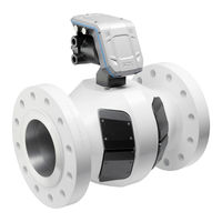
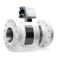
SICK FLOWSIC600-XT Gas Flow Meter Manuals
Manuals and User Guides for SICK FLOWSIC600-XT Gas Flow Meter. We have
2
SICK FLOWSIC600-XT Gas Flow Meter manuals available for free PDF download: Operating Instructions Manual, Service Manual
SICK FLOWSIC600-XT Operating Instructions Manual (164 pages)
Ultrasonic Gas Flow Meter
Brand:
SICK
| Category:
Measuring Instruments
| Size: 12 MB
Table of Contents
Table of Contents
4
1 Important Information
9
About this Document
10
Important Safety Information
10
Hazards Due to Hot, Corrosive and Explosive Gases, or High Pressure
10
Hazard through Heavy Loads
10
Hazard through Electromagnetic Interference
11
Intended Use
11
Product Identification
11
Purpose of the Device
11
Operation in Potentially Explosive Atmospheres
12
Operation in Pressure Applications
12
Restrictions of Use
12
Responsibility of User
13
Designated Users
13
Correct Use
14
Danger Identification on Device
14
Special Local Conditions
14
Retention of Documents
14
2 Product Description
15
Measuring Principle
16
System Components
16
Meter Body
17
Ultrasonic Transducers
17
Signal Processing Unit
17
Integrated Pressure and Temperature Sensor - Geometry Correction Via Pressure
17
And Temperature
17
Correction in FLOWSIC600-XT Electronics
18
Correction Outside the FLOWSIC600-XT Electronics (Volume Converter)
18
Features and Applications
20
FLOWSIC600-XT 2Plex
20
FLOWSIC600-XT Quatro
21
FLOWSIC600-XT Forte
21
Flowsic600-Xt C
22
FLOWSIC600-XT Gateway
22
Operating Software Flowgate TM
23
Overview
23
System Requirements
24
Access Rights
24
Operating Modes, Meter States and Signal Output
25
Measuring Mode
25
Air Test Mode
25
Configuration Mode
25
Interfaces
26
Analog Outputs
26
Digital Outputs
26
Encoder Totalizer
28
Serial Data Interfaces
29
Optical Data Interface
29
Totalizers
29
Diagnostics Function I-Diagnostics TM
29
Fingerprint System
30
Data Processing in FLOWSIC600-XT
32
Logbooks
32
Archives
33
Protection of Parameters from Undesired Changes
34
Sealing
35
Powerin Technology TM
37
3 Installation
39
Hazards During Installation
40
General Information
41
Delivery
41
Transport
41
Water Pressure Test in the Plant (Optional)
41
Mechanical Installation
42
Preparations
42
Choosing Flanges, Seals and Other Components
42
Requirements to the Measuring Point
42
Fitting in the Pipeline
43
Installation Configurations
45
Fitting the FLOWSIC600-XT in the Pipeline
54
Signal Processing Unit Alignment
56
Electrical Installation
57
Requirements for Use in Potentially Explosive Atmospheres
57
General Connection of the FLOWSIC600-XT
63
Criteria for Electrical Connection
64
Electrical Connections
64
Available Input/Output Configurations
67
Cable Specifications
68
Checking the Cable Loops
69
Connection Parameters of Inputs and Outputs
70
Safety-Relevant Parameters Ex-I
70
Connection Parameters Ex-D and Ex-E
71
Ex-D Terminal Compartment
72
Ex-E Terminal Compartment
74
Ex-I Terminal Compartment
76
Connecting the Optional Backup Battery
76
Connecting External Pressure and Temperature Sensors to the Electronics
77
4 Commissioning and Operation
79
General Information
80
Parameter Display on the Display
81
Opening the Display Protective Flap
81
Display and Operating Elements
82
Display in the Symbol Bar
82
Configurable Standard Display
83
Menu Structure
85
Commissioning with the Flowgate TM Operating Software
86
Connecting to the Device
86
Field Setup Wizard
87
Device Identification
87
System/User
88
I/O Configuration
89
P + T Pressure and Temperature Sensor
90
Volume Converters
90
Device Option)
90
Archives/Logbooks
90
Diagnostics/Warnings
90
Meter Installation
91
Completion
91
Function Check after Commissioning
91
Recommended Checks
91
Checking the Signal Acceptance Rate
92
Zero Phase Check
92
Checking the Speed of Sound
93
Path Failure Compensation
94
Sealing
94
5 Maintenance
95
General Information
96
Routine Checks
96
Checking the Meter State
96
Function Check on the Display
96
Function Check with Flowgate TM
97
Comparing Theoretical and Measured Sound Velocity (SOS)
98
Time Synchronization
100
Time Synchronization Via Modbus
100
Time Synchronization with the Flowgate™ Operating Software
100
Service Life/Capacity of RTC Battery
100
Maintenance Report
101
Optional Data Backup
102
Logbook Check and Data Backup
102
Checking the Data Archives (Data Logs)
103
Creating and Evaluating the Diagnostics Comparison Report
103
Exchanging the Battery
105
Battery Types
105
Information on Handling Lithium Batteries
105
Information on Storage and Transport
105
Disposal Information
105
Replacing the Backup Battery
107
Swivel the Display Unit Downwards
107
Remove the Backup Battery
108
Insert the New Backup Battery
108
Swivel the Display Unit Upwards and Lock
109
Replacing the RTC Battery
109
Cleaning the FLOWSIC600-XT
111
6 Shutting down
113
Returning
114
Contact
114
Packing
114
Disposal Information
114
Materials
114
Disposal
114
7 Troubleshooting
115
Status Messages
116
Starting a Diagnostic Session
117
8 Specifications
119
Conformities
120
CE Certificate
120
Standards Compatibility and Type Approval
120
WELMEC Conformity
120
Technical Data
121
Measuring Ranges
124
Dimensions
126
9 Annex
131
Connection Diagrams for Operation of the FLOWSIC600-XT in Accordance with
131
Atex/Iecex
131
Connection Diagrams for Operation of the FLOWSIC600-XT in Accordance with
132
Csa
141
Wiring Examples
150
Ex-D (Flameproof Enclosure)
150
Ex-E (Increased Type of Protection)
153
Ex-I (Intrinsically Safe)
156
Power Input of the Possible Input and Output Configurations
158
Type Plates (Examples)
159
Model Name
161
Spare Parts
162
Advertisement
SICK FLOWSIC600-XT Service Manual (68 pages)
Ultrasonic Gas Meter
Brand:
SICK
| Category:
Measuring Instruments
| Size: 3 MB
Table of Contents
Table of Contents
4
1 Important Information
7
About this Document
8
For Your Safety
9
Intended Use of the Device
9
Authorized Personnel
9
General Safety Instructions and Protective Measures
10
Hazards by Hot, Corrosive and Explosive Gases, or High Pressure
10
Hazard through Heavy Loads
11
2 Components
13
Complete Overview of the Device Family
14
FLOWSIC600-XT Forte
15
FLOWSIC600-XT 2Plex
16
FLOWSIC600-XT Quatro
17
SPU (Signal Processing Unit) Overview
18
Ex-D Enclosure Version
18
Ex-De Enclosure Version
19
Ex-I Enclosure Version
20
3 Repairs
21
General Information
22
Prerequisites for Repair Work
22
Tools Required
23
Working on the Meter Body
24
Replacing the Sensors
24
Remove the Sensors
24
Fit the New Sensor
26
Replacing the Integrated P/T Sensor
28
Remove the P/T Sensor
28
Fit the New P/T Sensor
29
Working on the SPU
31
Replacing the Display Unit
31
Swivel the Display Unit Downwards
31
Remove the Display Unit
32
Fit the New Display Unit
33
Connect the Display Unit
34
Swivel the Display Unit Upwards and Screw Tight
34
Replacing the Display Cover
35
Replacing the Backup Battery
36
Remove the Backup Battery
36
Insert the New Backup Battery
36
Replacing the RTC Battery
37
Replace the RTC Battery
37
Replacing the SPU Circuit Board
38
Remove the Electronics Cover
38
Remove the SPU Circuit Board
39
Fit the New SPU Circuit Board
40
Fit the Electronics Cover
41
Replacing the Ex-D I/O Block
42
Open the Ex-D Terminal Compartment
42
Remove the Ex-D I/O Block
42
Fit the New Ex-D I/O Block
44
Close the Ex-D Terminal Compartment
45
Replacing the Ex-D I/O Block Fuse
46
Replacing the Ex-E Connection Block
47
Open the Ex-E Terminal Compartment
47
Remove the Connection Blocks in the Ex-E Terminal Compartment
48
Fit the New Connection Block in the Ex-E Terminal Compartment
48
Close the Ex-E Terminal Compartment
49
Replacing the Cable Gland between the Ex-D and Ex-E Terminal Compartments
50
Remove the Cable Gland
50
Fit the Ex-E Cable Gland
51
Transducer Electronics
52
Remove the Cable Gland
52
Fit the New Cable Gland
53
Parameter Input
54
Configure Sensor Settings after Transducer Exchange
54
SOS Check
54
Configure Stacking
55
Configure Zerophase
55
Configure Pfix and Tfix
55
4 Accessories and Spare Parts
57
SPU Parts
58
Electronic Boards
58
Transducers
59
Pressure/Temperature Sensors
59
O-Rings for Transducers
59
Electronics Accessories
59
Transducer Covers
60
Covers P/T Sensor
61
Accessories Meter Body
61
5 Annex
63
Component Placement Specification SPU (Sensor Cables)
64
Advertisement
Related Products
SICK FLOWSIC600
SICK FLOWSIC60
SICK FLOWSIC500
Sick FLOWSIC100 Flare
SICK FLOWSIC30
SICK FLOWSIC100 Flare-XT
SICK FLOWSIC100-XT-P
SICK FLOWSIC100-XT-R
SICK FLOWSIC100-XT-M
SICK FLOWSIC100-XT-H
SICK Categories
Accessories
Security Sensors
Measuring Instruments
Scanner
Barcode Reader
More SICK Manuals
Login
Sign In
OR
Sign in with Facebook
Sign in with Google
Upload manual
Upload from disk
Upload from URL