Table of Contents
Advertisement
Quick Links
Download this manual
See also:
Instruction Manual
SERVICE MANUAL
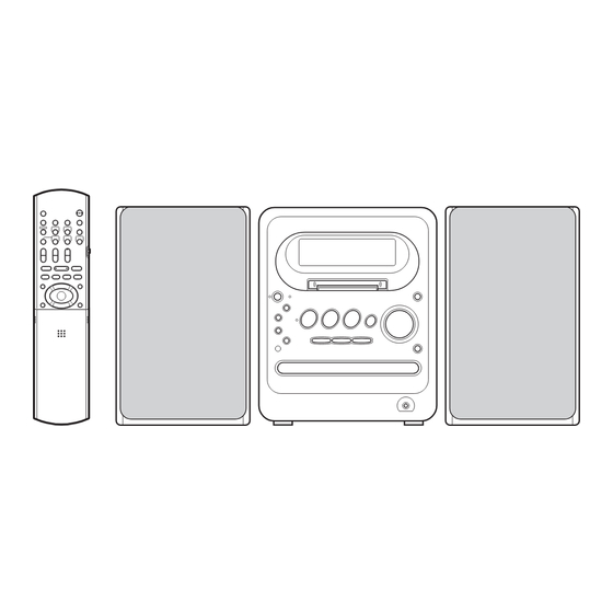
MICRO COMPONENT MD SYSTEM
12
2005
MB496
UX-QD70S,UX-QD70W
Lead free solder used in the board (material : Sn-Ag-Cu, melting point : 219 Centigrade)
1
PRECAUTION. . . . . . . . . . . . . . . . . . . . . . . . . . . . . . . . . . . . . . . . . . . . . . . . . . . . . . . . . . . . . . . . . . . . . . . . . 1-4
2
SPECIFIC SERVICE INSTRUCTIONS . . . . . . . . . . . . . . . . . . . . . . . . . . . . . . . . . . . . . . . . . . . . . . . . . . . . . . 1-8
3
DISASSEMBLY . . . . . . . . . . . . . . . . . . . . . . . . . . . . . . . . . . . . . . . . . . . . . . . . . . . . . . . . . . . . . . . . . . . . . . . 1-9
4
ADJUSTMENT . . . . . . . . . . . . . . . . . . . . . . . . . . . . . . . . . . . . . . . . . . . . . . . . . . . . . . . . . . . . . . . . . . . . . . . 1-43
5
TROUBLESHOOTING . . . . . . . . . . . . . . . . . . . . . . . . . . . . . . . . . . . . . . . . . . . . . . . . . . . . . . . . . . . . . . . . . 1-53
(SP-UXK30S)
(SP-UXK30W)
TABLE OF CONTENTS
COPYRIGHT © 2005 Victor Company of Japan, Limited
(CA-UXQD70S)
(CA-UXQD70W)
Area suffix
UB ---------------------- Hong Kong
(SP-UXK30S)
(SP-UXK30W)
No.MB496
2005/12
Advertisement
Chapters
Table of Contents

Related Manuals for JVC UX-QD70S


Summary of Contents for JVC UX-QD70S
-
Page 1: Table Of Contents
SERVICE MANUAL MICRO COMPONENT MD SYSTEM MB496 2005 UX-QD70S,UX-QD70W Area suffix UB ---------------------- Hong Kong (SP-UXK30S) (CA-UXQD70S) (SP-UXK30S) (SP-UXK30W) (CA-UXQD70W) (SP-UXK30W) Lead free solder used in the board (material : Sn-Ag-Cu, melting point : 219 Centigrade) TABLE OF CONTENTS PRECAUTION............... . . 1-4 SPECIFIC SERVICE INSTRUCTIONS . - Page 2 SPECIFICATION MD/DVD receiver (CA-UXQD70S/CA-UXQD70W) 20 W × 2 (10% THD/4 Ω) Amplifier Output power AUX × 1 Input terminals Analog 650 mV/47 kΩ: LEVEL1 260 mV/47 kΩ: LEVEL2 Digital optical input × 1 Digital -23 dBm to -15 dBm (Optical square terminal) (Compatible with frequency of 32 kHz, 44.1 kHz and 48 kHz) Speaker ×...
- Page 3 85 dB/W·m 135 mm (W) × 200.5 mm (H) × 213.5 mm (D) Dimensions Mass (approx.) 2.1 kg (1 unit) Micro component MD system (UX-QD70S/UX-QD70W) 435 mm (W) × 200.5 mm (H) × 350 mm (D) Dimensions Mass (approx.) 9.3 kg U.S.
-
Page 4: Precaution
SECTION 1 PRECAUTION Safety Precautions (1) This design of this product contains special hardware and voltmeter. many circuits and components specially for safety purpos- Move the resistor connection to each exposed metal es. For continued protection, no changes should be made part, particularly any exposed metal part having a return to the original design unless authorized in writing by the path to the chassis, and measure the AC voltage across... - Page 5 Preventing static electricity Electrostatic discharge (ESD), which occurs when static electricity stored in the body, fabric, etc. is discharged, can destroy the laser diode in the traverse unit (optical pickup). Take care to prevent this when performing repairs. 1.5.1 Grounding to prevent damage by static electricity Static electricity in the work area can destroy the optical pickup (laser diode) in devices such as laser products.
- Page 6 Attention when pickup unit is removed 1.7.1 Attention when MD pickup unit is removed *Please refer to "DISASSEMBLY" in the text. (1) Apply solder to short land section before the flexible wire is disconnected from the connector CN310 on the MD servo control board.
-
Page 7: Important For Laser Products
Important for laser products 5.CAUTION : If safety switches malfunction, the laser is able 1.CLASS 1 LASER PRODUCT to function. 2.DANGER : Invisible laser radiation when open and inter 6.CAUTION : Use of controls, adjustments or performance of lock failed or defeated. Avoid direct exposure to beam. procedures other than those specified here in may result in 3.CAUTION : There are no serviceable parts inside the hazardous radiation exposure. -
Page 8: Specific Service Instructions
SECTION 2 SPECIFIC SERVICE INSTRUCTIONS This service manual does not describe SPECIFIC SERVICE INSTRUCTIONS. 1-8 (No.MB496) -
Page 9: Disassembly
SECTION 3 DISASSEMBLY Main body section 3.1.1 Removing the rear cover(B) (See Figs.1 and 2) (1) From the back side of the main body, remove the twelve screws A attaching the rear cover(B). (See Fig.1.) (2) From the bottom side of the main body, remove the three screws B attaching the rear cover(B). - Page 10 3.1.2 Removing the side panels (L)/(R) (See Fig.3) • Remove the rear cover(B). (1) From the bottom side of the main body, remove the two Side panel (R) screws C attaching the side panels (L)/(R). (2) Slide the side panels (L)/(R) in the direction of the arrow and remove the side panels (L)/(R).
- Page 11 3.1.4 Removing the front panel assembly (See Figs.6 to 8) • Remove the rear cover(B), side panels(L)/(R) and top cover assembly. Front panel assembly (1) From the left side of the main body, disconnect the card wires from the connectors (CN702, CN710) on the micon board.
- Page 12 3.1.5 Removing the fan motor (See Figs.9 and 10) • Remove the rear cover(B), side panels(L)/(R) and top cover assembly. Tuner bracket (1) From the back side of the top cover assembly, remove the Fan motor screw F attaching the fan motor. (See Fig.9.) (2) Take out the fan motor.
- Page 13 3.1.8 Removing the heat sink(B) (See Fig.11) • Remove the rear cover(B), side panels(L)/(R) and top cover assembly. Heat sink bracket (1) From the back side of the main body, remove the three Heat sink(B) screws K and two screws M attaching the heat sink(B). (2) Remove the heat sink(B) from the main body.
- Page 14 3.1.11 Removing the regulator board (See Fig.14) • Remove the rear cover(B), side panels(L)/(R), top cover as- sembly, heat sink(B) and main board. (1) From the top side of the main body, disconnect the wire CN902 from the connector CN902 on the trans board.
- Page 15 3.1.14 Removing the power transformer (See Fig.16) • Remove the rear cover(B), side panels(L)/(R), top cover as- sembly, heat sink(B), main board, regulator board and trans board. (1) From the reverse side of the trans board, remove the sol- ders from the sections e on the trans board. (2) Remove the power transformer from the trans board.
- Page 16 3.1.16 Removing the MD mechanism assembly (See Figs.18 to 20) • Remove the rear cover(B), side panels(L)/(R), top cover as- sembly, front panel assembly, heat sink(B) and main board. MD mechanism assembly (1) From the both side of the main body, remove the four screws V attaching the MD mechanism assembly.
- Page 17 3.1.18 Removing the micon board (See Fig.21) • Remove the rear cover(B), side panels(L)/(R), top cover as- sembly, front panel assembly, heat sink(B), main board, MD Trans board mechanism assembly, MD holder and regulator board. CN711 CN705 CN805 CN903 (1) Disconnect the wire from the connector CN903 on the trans board.
- Page 18 3.1.20 Removing the DVD mechanism assembly (See Fig.23) • Remove the rear cover(B), side panels(L)/(R), top cover as- sembly, heat sink(B), main board, regulator board, trans board, CD mechanism bracket and joint board. (1) From the top side of the main body, remove the screw Z at- taching the DVD mechanism assembly.
- Page 19 3.1.22 Removing the key board (See Fig.25) • Remove the rear cover(B), side panels(L)/(R), top cover as- sembly and front panel assembly. Key board (1) From the inside of the front panel assembly, remove the five screws AB attaching the key board. (2) Take out the key board from the front panel assembly.
-
Page 20: See Figs.1 And
DVD mechanism assembly • Remove the DVD mechanism assembly from main body. (Refer the Disassembly method) 3.2.1 Removing the DVD cover (See fig.1 and 2) (1) Remove the two screws A attaching the DVD cover from top side of DVD mechanism assembly. (See fig.1) (2) Remove the card wire from the connector on the LED assembly. - Page 21 3.2.2 Removing the tray assembly (See fig.3 and 4) • Remove the DVD cover. (1) From the right-hand side of a DVD mechanism assembly, Tray assembly DVD mechanism assembly a slide cam is pushed and a tray assembly is pulled out in the direction of an arrow.
- Page 22 3.2.3 Removing the LED assembly (See fig. 5) • Remove the DVD cover and tray assembly. (1) From the upper surface of a tray assembly, the double-sid- ed tape which has attached the LED assembly is removed, and a LED board is removed. Tray assembly Double face tape LED assembly...
- Page 23 3.2.5 Removing the DVD servo board (See fig.7 and 8) • Remove the DVD cover and traverse mechanism. (1) The short land section b of a pickup is soldered. (See fig.7) DVD pickup Caution: • Please solder to the short land section b of a pickup before removing a card wire from the connector CN101 of a DVD servo board.
- Page 24 3.2.6 Removing the pickup (See fig.7 to 11) • Remove the DVD cover and traverse mechanism assembly. (1) The short land section b of a pickup is soldered. (See fig.7) Traverse mechanism assembly Caution: Rod spring • Please solder to the short land section b of a pickup Guide chaft before removing a card wire from the connector of pickup.
- Page 25 3.2.7 Attaching the pickup (See fig.9 to 12) • Refer the "Removing the pickup". (1) Attach the guide shaft, lock arm and lock arm spring to Screw shaft gear DVD pickup. (See fig.11) (2) A pickup is united with the j section of a traverse mecha- nism assembly, and the both ends of a pickup shaft are at- tached in the g section and the h section.
- Page 26 3.2.9 Removing the spindle motor board (See fig.13 and 14) • Remove the DVD cover, traverse mechanism assembly and DVD servo board. Traverse mechanism assembly (1) Remove the yellow wire and white wire from soldered sec- tion k of spindle motor board. (See fig.13) (2) Remove the three screws H attaching the feed motor board.
- Page 27 MD mechanism assembly • Remove the MD mechanism assembly from main body. (Refer to "Removing the MD mechanism assembly" of main unit.) 3.3.1 Removing he MD servo control board (See fig.1 and 2) (1) Remove the card wire from connector CN408 on MD servo control board, and then remove the flexible wire from con-...
- Page 28 3.3.2 Removing the mecha cover (See fig.3) (1) Remove the four screws B attaching the mecha cover. Fixing part c (2) Remove the hook from fixing part c of the internal loading assembly. Mecha cover (3) Shift the mecha cover to front side, and then remove to up- per direction.
-
Page 29: See Fig.7 And
3.3.4 Removing the head assembly (See fig.7 and 8) • Remove the MD servo control board. Rest switch (1) Remove the wire from head assembly to fixed bottom part Pickup of pickup. (See fig.7) (2) Remove the screw C attaching the head assembly. (See fig.8) Caution: Wire... -
Page 30: No.mb496)1
3.3.5 Removing the loading assembly and traverse mechanism assembly (See fig.9 and 10) • Remove the MD servo control board, mecha cover, head lifter and head assembly. (1) Remove the three screws D attaching the loading assem- Loading assembly bly from upper side of main body. (See fig.9) (2) Shift the loading assembly to front side, and then discon- nect the fixing part f of traverse mechanism assembly. - Page 31 3.3.6 Removing the slide base (L) and slide base (R) (See fig.11) • Remove the MD servo control board, mecha cover, head lifter, head assembly and loading assembly. Slide base (R) Fixing part g (1) Remove the two screws E attaching the slide base (L) and slide base (R) from upper side of loading assembly.
-
Page 32: No.mb496)1
3.3.8 Removing the loading motor (See fig.13 and 14) • Remove the MD servo control board, mecha cover, head lifter, Loading motor assembly head assembly, loading assembly and loading mechanism as- sembly. Wireholder (1) Disconnect the card wire from connector CN612 of cam Fixing part i... - Page 33 3.3.10 Removing the slide bar and cartridge holder assembly (See fig.15 and 16) • Remove the MD servo control board, mecha cover, head lifter, Slide ber Cartridge holder assembly head assembly, loading assembly and loading mechanism as- sembly. (1) Remove the two screws J attaching the slide cover to fix cartridge holder assembly from upper surface of loading assembly.
- Page 34 3.3.12 Removing the insulator (See fig.17) • Remove the MD servo control board, mecha cover, head lifter, Insulator head assembly and traverse mechanism assembly. (1) Remove the insulator from cut part of traverse mecha Pickup unit chassis at upper surface of traverse mechanism. Traverse mecha chassis Insulator Fig.17...
- Page 35 3.3.15 Removing the feed motor assembly (See fig.20 and 21) • Remove the MD servo control board, mecha cover, head lifter, Traverse mechanism assembly Spindle motor head assembly, traverse mechanism assembly and insulator. (1) Remove the white wire and black wire attached soldered Soldered section n Pickup section m of traverse mechanism board.
- Page 36 3.3.17 Attaching the loading assembly (See fig.22 to 29) (1) Attach the eject bar to UD base. (See fig.22 and 23) Slide bar (2) A slide bar is attached to loading mecha chassis, uniting the p section of the boss of a slide bar with the slot of an ejection bar.
- Page 37 Slot r mark Cartridge holder assembly Boss Loading Cam switch slider Cam switch board Loading motor assembly CN612 Part q pin Wire holder Eject bar Bend part v Fig.24 Slide bar Slit washer Cam gear Eject bar Cam gear mark) Part u Eject bar Fig.25...
- Page 38 Slide base(R) Slide base(L) Boss aa Part x Part x Part w Boss aa Fig.29 Loading mecha base Fig.26 Slide base(R) Bend part y Slide base(L) Part z Fig.27 Slide base(R) Cam gear Part z Bend part y Fig.28 1-38 (No.MB496)
- Page 39 Cassette mechanism assembly 3.4.1 Removing the Play/Record & Clear head Cassette mechanism assembly Fly wheelR (See Fig.1~3) (1) While moving the trigger arm on the right side of the head mount in the direction of the arrow, turn the flywheel R counterclockwise until the head mount comes ahead and clicks.
- Page 40 3.4.2 Removing the head amplifier & mechanism control board (See Fig.4) (1) Turn over the cassette mechanism assembly and remove Main motor assembly the three screws A attaching the head amplifier & mecha- nism control board. Capstan belt (2) Disconnect the flexible wire from connector CN31 on the head amplifier &...
- Page 41 3.4.4 Removing the flywheel (See Fig.8, 9) • Prior to performing the following procedure, remove the head amplifier & mechanism control board and the main motor as- sembly. (1) From the front side of the cassette mechanism, remove the slit washers attaching the capstan shaft L and R. Pull out the flywheels backward.
- Page 42 3.4.6 Reattaching the Play/ Record & Clear head (See Fig.11~13) (1) Reattaching the head mount assembly. a) Change front of the direction cover of the head mount assembly to the left (Turn the head forward). b) Fit the bosses O', P', Q', U' and V' on the head mount assembly to the holes P and V, the slots O, U and Q of the mechanism sub assembly (See Fig.11 to 13).
-
Page 43: Adjustment
SECTION 4 ADJUSTMENT Jigs and test instruments (1) Laser power meter (Wavelength : 780um) (2) Laser power meter sensor (disk type) (3) Premastered disk (4) Recordable disk Adjustment and check items 4.2.1 Test mode 4.2.3 DVD section (1) FL display all lighting-up mode (1) Setup of the TEST MODE (2) Initialization setting in shipment 4.2.2 MD section... - Page 44 (3) Setup of the laser power MD TEST 1 Insert the laser power meter sensor. Insert the laser power meter sensor. Press the [MD EJECT ] A laser power meter key on the main unit. sensor is ejected. Press the [4] key on MD mechanism starts the remote controller.
- Page 45 (5) Iop check In the MD test mode 1, when [ 0 ] key is pressed, the Iop display is performed by the following methods. Purpose: In order to check pick failure and static electricity failure by the laser ON current. Measurement means: "Laser ON current"...
- Page 46 (6) Adjustment of the disk Insert the recordable disk MD TEST 1 for the adjustment. Insert the premastered Press the [MD PLAY disk for the adjustment. key on the remote controller. Reading of TOC ends. FL display ON TUNING Press the [MD PLAY key on the remote controller.
- Page 47 (7) Setup of the TEST MODE 2 While pressing both the [STOP ] key and [MD PLAY ] key on the main unit, insert the AC power cord in an outlet. Press the [STOP ] key and FL display [MD EJECT ] key on the main unit MD TEST at the same time.
- Page 48 3. DVD section Attention in service of DVD section 1. When pickup, Flash ROM, DVD module board were changed, initialize EEPROM by all means. 2. When full initialization was executed, execute learning with a DVD test disk by all means. Test disc : VT-501, VT-502 Learning method : It is adjusted automatically by normal playback of a DVD test disc.
- Page 49 (5) Check mode FL display TEST JC# Press the [MENU] key on the main unit FL display CHECK Press the [5] key on the main unit FL display Upper side Lighting of DVD LD 4 digit: Laser current display Press the [6] key on the main unit FL display Lower side...
-
Page 50: No.mb496)1
4. Error history (1) Outline The failure that is not reproduced may occur in a market. Presumption of the cause of failure is difficult. This error log is recorded when failure occurs. It is displayed again and can use to service. Using the EEPROM of 256bytes. - Page 51 (4) ERROR details Item Low address and contents address SAFETY Number SAFETY error number (When SAFETY ERROR detecting, main unit is non active.) DVD4.0V DVDA6V VIDEO5V SW10V MD5.4V AD value AD value at SAFETY error 00 to FF Timer playback is not starting DVD,CD NODISC DVD,CD OPEN TAPE NONE...
- Page 52 Item low address and contents Address Time out of power OFF process DVD,CD TIMEOUT MD TIMEOUT MECHA CLOSE TIMEOUT Others Error with DVD MECHA CLOSE TIMEOUT MECHA OPEN TIMEOUTMD Error with MD TRACK_PROTECTED CANNOT_JOIN (Reserve) CANNOT_TITLE GROUP_FULL GROUP_FULL GROUP_TRACK CANNOT_FORM CANNOT_ENTRY LOAD_ERROR MD_NO_DISC...
-
Page 53: Troubleshooting
SECTION 5 TROUBLESHOOTING This service manual does not describe TROUBLESHOOTING. (No.MB496)1-53... - Page 54 Victor Company of Japan, Limited Audio/Video Systems Category 10-1,1chome,Ohwatari-machi,Maebashi-city,371-8543,Japan (No.MB496) Printed in Japan...
- Page 55 SCHEMATIC DIAGRAMS MICRO COMPONENT MD SYSTEM UX-QD70S,UX-QD70W CD-ROM No.SML200512 Area suffix UB ---------------------- Hong Kong (SP-UXK30S) (CA-UXQD70S) (SP-UXK30S) (SP-UXK30W) (CA-UXQD70W) (SP-UXK30W) Lead free solder used in the board (material : Sn-Ag-Cu, melting point : 219 Centigrade) Contents Block diagrams Standard schematic diagrams...
- Page 56 In regard with component parts appearing on the silk-screen printed side (parts side) of the PWB diagrams, the parts that are printed over with black such as the resistor ( ), diode ( ) and ICP ( ) or identified by the " " mark nearby are critical for safety.
-
Page 57: Block Diagram
Block diagram MD servo control section Jack section Main section Cassette mechanism section IC390 HEAD SWITCH DRAM L+, L– PBL,PBR IC32 COMPONENT RECL, RECR MECHA R+, R– RECL,RECR RDT0A to RDT3A PB/REC VIDEO OUT TAPEL, TAPER HEAD RAD0A to RAD11A LRCKI NWEA, NRASA LM+, LM-... - Page 58 Standard schematic diagrams Transformer section LVA10596-A2 LVA10596-A2 LVA10596-A3 LVA10596-A3 S 1 G N D T 9 0 0 1 S 1 + Q Q T 0 4 9 6 - 0 0 1 R 2 4 0 2 1 0 k F A N U P C N 9 0 2 S 2 G N D...
- Page 59 Main section LVA10595-A1 LVA10595-A1 K T C 3 8 7 5 / Y G / - X Q 3 1 0 1 R 3 1 1 1 I C 1 0 1 R 3 1 9 3 A U X L 1 0 k L A 4 6 2 8 0 .
- Page 60 System control section (SHEET 8) (SHEET 1) (SHEET 9) TO TAPE TO TUNER TO LVA10596-A3 TO DVD MECHA SLC-S302M CN33 CN903 QAU0346-001 FMU-UM1-31M R E V S U M I C A R D C N 7 0 9 Q G F 1 2 0 5 C 1 - 1 1 W R 7 0 1 C N 7 1 1 C N 7 0 3...
- Page 61 Jack section COMPONENT VIDEO OUT J 6 3 0 1 Q N N 0 6 6 1 - 0 0 1 C 6 3 2 7 C 6 3 2 8 C 6 3 2 4 0 . 0 1 0 .
- Page 62 MD servo control section VREF C370 IC390 MSM51V17405F5TS X300 RDT0A RDT3A NAX0476-001X RDT1A RDT2A R319 NWEA NCASA R320 NRASA C359 R322 0.47 TP944 RAD11A RAD9A R321 NRFSTBY R350 ADIP 1.5k TP413 TEMP RFSWPG R351 TP365 RAD10A RAD8A C363 C310 RFSWHL R352 RAD0A RAD7A...
- Page 63 DVD servo control section (1/2) P3.3V D1.2V IC302 IC302 MM1701CH-X C328 0.01 R327 DGND R330 DACPDN R331 ADCRST DAC1CS DVDPWR R332 DAC2CS C372 R318 SWMUTE TP325 TP320 CPURST C102 C376 C373 TP328 VREFH TP329 DGND C101 TP330 TP331 R104 E3+F3 R112 TP332 E4+F4...
- Page 64 DVD servo control section (2/2) IC708 R734 K731 NQR0251-004X IC505 IC509 K4S641632H-UC75 DATAM K732 NQR0251-004X SG32M90TFIR3 C730 DEMP EXADT15 EXADR16 C551 LRCKM K733 NQR0251-004X R733 EXADT14 MDQ0 MDQ15 COPY EXADT13 TRACK EXADT12 EXDT15 MDQ1 MDQ14 P3.3V INDEX EXADT11 EXDT7 MDQ2 C563 C562 MDQ13...
- Page 65 LED & DVD loading section UDZS7.5B-X UDZS7.5B-X NSTM515AS QGF1006F2-07W TO CN705 (SHEET 3) UDZS7.5B-X UDZS7.5B-X NSTM515AS QSW1074-001 TO CN711 (SHEET 3) QGF1016F3-05 SHEET 8...
- Page 66 R371 R108 RECL R106 R302 R110 2.2K C214 150P/50 CN42 Q342 QGF1205F1-09 C104 VR37 KRA111M-T C102 QVP0077-103Z 0.01/16 Q343 R306 2SC3576-JVC-T 4.7K R336 R344 Q344 C340 2SC3576-JVC-T 47/50 CN32 4.7K QGF1205F1-09 C208 0.01/50 R339 C341 Q345 R345 100K 1/50 C304...
-
Page 67: Printed Circuit Boards
Printed circuit boards Main board Lead free solder used in the board (material : Sn-Ag-Cu, melting point : 219 Centigrade) (Main board) (Headphone board) R6079 CN110 K6001 R3402 R6070 C6074 B1937 C6071 R1206 R6071 C1205 B1919 D1203 IC601 C6072 D1103 R2803 R1205 WR101... - Page 68 Micom board Lead free solder used in the board (material : Sn-Ag-Cu, melting point : 219 Centigrade) (Transformer board) (Video board) J6301 (Micom board) CN706 R7301 R7302 EB701 LF901 T9002 CN707 R7391 D7601 C6323 Q7901 C6322 R7392 R7186 TP701 Q7903 Q7902 R7904 R7901...
- Page 69 MD servo control board Lead free solder used in the board (material : Sn-Ag-Cu, melting point : 219 Centigrade) Forward side Reverse side (MD servo control board) (MD servo control board) TP560 TP561 C494 R495 TP556 CN521 IC450 C521 R368 TP557 CN522 TP450...
- Page 70 DVD servo control board Lead free solder used in the board (material : Sn-Ag-Cu, melting point : 219 Centigrade) Forward side Reverse side (DVD servo control board) (DVD servo control board) R342 C318 C730 C564 R541 R734 IC510 K731 K501 IC708 C558 R701...
- Page 71 Cassette switch board Lead free solder used in the board (material : Sn-Ag-Cu, melting point : 219 Centigrade) VR37 R371 FW100 Head amplifier board Lead free solder used in the board (material : Sn-Ag-Cu, melting point : 219 Centigrade) CN33 C374 PP300 R310...
- Page 72 Victor Company of Japan, Limited Audio/Video Systems Category 10-1,1chome,Ohwatari-machi,Maebashi-city,371-8543,Japan Printed in Japan (No.MB496SCH)
-
Page 73: Parts List
PARTS LIST [ UX-QD70S ] [ UX-QD70W ] * All printed circuit boards and its assemblies are not available as service parts. UX-QD70S, UX-QD70W Area suffix UB --------------------- Hong Kong - Contents - Exploded view of general assembly and parts list (Block No.M1) Speaker assembly and parts list (Block No.M2) - Page 74 Exploded view of general assembly and parts list Block No. Key board LCD board Holder board...
- Page 75 Micom board Joint board Trans board Regulator board Jack board y board Headphone board Main board...
- Page 76 General Assembly Block No. [M][1][M][M] Symbol No. Part No. Part Name Description Local LV11119-010A FRONT PANEL LV11119-011A FRONT PANEL LV40301-002A FELT SPACER (x2) LV30225-011A SPACER (x2) LV22047-004A FRONT LENS LV22047-005A FRONT LENS GV30489-003A MD LID GV30489-004A MD LID LV43984-001A SPRING QYSDSF2608ZA TAP SCREW...
- Page 77 Symbol No. Part No. Part Name Description Local QYSBSG3010ZA TAP SCREW M3 x 10mm(x2) LV36035-002A HEAT SINK(B) QYSBSG3014EA TAP SCREW M3 x 14mm QYSBSG3014EA TAP SCREW M3 x 14mm QYSBSG3014EA TAP SCREW M3 x 14mm(x2) LV30225-0V8A SPACER LV21844-017A TOP COVER ASSY LV21844-018A TOP COVER ASSY VKL7850-003...
-
Page 78: Speaker Assembly And Parts List (Block No.m2)
Block No. The parts without symbol number are not service. Speaker Block No. [M][2][M][M] Symbol No. Part No. Part Name Description Local LV22084-010A SPK NET (x2) LV22084-011A SPK NET (x2) 9000007941 FOOT (x8) LV43473-002A JVC MARK (x2) 5600008011 HOLDER (x8) -
Page 79: Md Mechanism Assembly And Parts List (Block No.me)
MD mechanism assembly and parts list Block No. FMU-S8M-21M Grease =JVG-31N =CFD-4007ZY2 10.0 0.2mm 61.5 0.1mm 35 42 MD cam switch board 7.0 0.2mm MD servo control board The parts without symbol number are not service. - Page 80 MD mechanism Block No. [M][E][M][M] Symbol No. Part No. Part Name Description Local LV20548-033A LOADING ASSY LV31472-004A CAM GEAR QYWDL1230252 SLIT WASHER 3mm/1.2mm x 0.25mm LV41477-004A MINI TAP SCREW (x2) LV32168-002A WIRE HOLDER LV31710-002A L.MOTOR ASSY QAR0251-002 MOTOR WJM0117-003A-E E-SI C WIRE C-F LV41341-001A MOTOR PULLEY...
-
Page 81: Dvd Mechanism Assembly And Parts List (Block No.mj)
DVD mechanism assembly and parts list Block No. Grease =JVG-31N FTU-UM1-31M =JVS-1003 2.4mm + 0.1mm Letter side APPLY AREA 7.0mm + 0.1mm Reverse side module board The parts without symbol number are not service. - Page 82 DVD mechanism Block No. [M][J][M][M] Symbol No. Part No. Part Name Description Local LV10984-001A S.TM CHASSIS QAR0334-002 S.MOTOR QYSPSPU1740ZA SCREW M1.7 x 4mm(x3) QAR0144-003 MOTOR VKS5557-001 F.M. GEAR QYSPSPT2025ZA SCREW M2 x 2.5mm LV35461-002A MIDDLE GEAR LV44040-001A SCREW SHAFT LV35462-001A SCREW SHAFT GEA QAL0667-001...
-
Page 83: Dvd Loading Base Assembly And Parts List (Block No.mn)
DVD loading base assembly and parts list Block No. FMU-UM1-31M Grease JVS-1003 CFD-4007ZY2 Back side Front side Backside In side DVD loading switch board The parts without symbol number are not service. 3-11... - Page 84 DVD loading base Block No. [M][N][M][M] Symbol No. Part No. Part Name Description Local LV11065-004A LOADER SUB ASSY E407140-001SS C.D ROLLER E407149-001SS RUBBER TUBE LV11125-002A TRAY NSTM515AS NSTM515AS LV35499-003A SHAFT GUIDE LV44022-001A SHAFT QYSSSP2010ZA SCREW M2 x 10mm QYNNS2000ZA QYSDSF2008ZA TAP SCREW M2 x 8mm(x2)
-
Page 85: Cassette Mechanism Assembly And Parts List (Block No.mp)
Cassette mechanism assembly and parts list Block No. SLC-S304M Grease = EM-30L =UD-24 =LEN-320M =MOBIL-1 The lower side Switch board Head amplifier board The parts without symbol number are not service. 3-13... - Page 86 Cassette mechanism Block No. [M][P][M][M] Symbol No. Part No. Part Name Description Local VKS1165-00N CHASSIS B. ASSY VKS2274-002 REEL GEAR (x2) VKW5286-002 B.T. SPRING (x2) VKS5559-001 PLAY IDLE GEAR VKS5595-002 BLIND VKS5560-003 FR IDLE GEAR LV42013-001A EARTH SPRING SLC-RP4SVM HEAD MOUNT ASSY VKY3149-002 CASSETTE SP.
-
Page 87: Electrical Parts List
DIGI TRANSISTOR C3104 QETN1HM-475Z E CAPACITOR 4.7uF 50V M Q1102 UN211E-X DIGI TRANSISTOR C3105 QTE1V39-106Z E CAPACITOR 10uF 35V Q1103 2SC3576-JVC-T TRANSISTOR C3106 QETN1HM-475Z E CAPACITOR 4.7uF 50V M Q1201 UN211E-X DIGI TRANSISTOR C3107 QFG32AJ-821Z PP CAPACITOR 820pF 100V J... - Page 88 Symbol No. Part No. Part Name Description Local Symbol No. Part No. Part Name Description Local C6006 QFVF1HJ-104Z MF CAPACITOR 0.1uF 50V J R3209 NRSA63J-392X MG RESISTOR 3.9kΩ 1/16W J C6007 QFVF1HJ-104Z MF CAPACITOR 0.1uF 50V J R3210 NRSA63J-103X MG RESISTOR 10kΩ...
- Page 89 Micon board Symbol No. Part No. Part Name Description Local Block No. [0][2] R8013 NRSA63J-471X MG RESISTOR 470Ω 1/16W J R8026 QRE141J-331Y C RESISTOR 330Ω 1/4W J Symbol No. Part No. Part Name Description Local R8027 NRSA63J-0R0X MG RESISTOR 0Ω...
- Page 90 Symbol No. Part No. Part Name Description Local Symbol No. Part No. Part Name Description Local R2602 NRSA63J-564X MG RESISTOR 560kΩ 1/16W J C2401 QETM1EM-828 E CAPACITOR 8200uF 25V M R2603 NRSA63J-331X MG RESISTOR 330Ω 1/16W J ...
- Page 91 Symbol No. Part No. Part Name Description Local Symbol No. Part No. Part Name Description Local R7071 NRSA63J-332X MG RESISTOR 3.3kΩ 1/16W J R7808 QRE141J-101Y C RESISTOR 100Ω 1/4W J R7072 NRSA63J-102X MG RESISTOR 1kΩ 1/16W J R7809 QRE141J-181Y C RESISTOR 180Ω...
- Page 92 MD servo control board Symbol No. Part No. Part Name Description Local Block No. [0][3] C460 NCF31AZ-105X C CAPACITOR 1uF 10V Z Symbol No. Part No. Part Name Description Local C464 NCF31EZ-104X C CAPACITOR 0.1uF 25V Z C465 NEAG1CM-106X E CAPACITOR 10uF 16V M...
- Page 93 Symbol No. Part No. Part Name Description Local Symbol No. Part No. Part Name Description Local R417 NRSA63J-222X MG RESISTOR 2.2kΩ 1/16W J K492 NRSA63J-0R0X MG RESISTOR 0Ω 1/16W J R422 NRSA63J-103X MG RESISTOR 10kΩ 1/16W J K495 NRSA63J-0R0X MG RESISTOR 0Ω...
- Page 94 Symbol No. Part No. Part Name Description Local Symbol No. Part No. Part Name Description Local C211 NCB31HK-223X C CAPACITOR 0.022uF 50V K C560 NCF31EZ-104X C CAPACITOR 0.1uF 25V Z C217 NCF31EZ-104X C CAPACITOR 0.1uF 25V Z C562 NCF31AZ-105X C CAPACITOR 1uF 10V Z...
- Page 95 Q305 2SC2001/K/-T TRANSISTOR R731 NRSA63J-102X MG RESISTOR 1kΩ 1/16W J Q342 KRA111M-T DIGI TRANSISTOR R732 NRSA63J-102X MG RESISTOR 1kΩ 1/16W J Q343 2SC3576-JVC-T TRANSISTOR R733 NRSA63J-0R0X MG RESISTOR 0Ω 1/16W J Q344 2SC3576-JVC-T TRANSISTOR Q345 2SC3576-JVC-T TRANSISTOR CN101 QGF0523F1-25W CONNECTOR...
- Page 96 Symbol No. Part No. Part Name Description Local C314 QCFB1HZ-105Y C CAPACITOR 1uF 50V Z C316 QFG32AJ-223Z PP CAPACITOR 0.022uF 100V J C319 QFLC1HJ-472Z M CAPACITOR 4700pF 50V J C331 QEKJ1CM-476Z E CAPACITOR 47uF 16V M C340 QEKJ1CM-476Z E CAPACITOR 47uF 16V M C341 QEKJ1HM-105Z...
- Page 97 <MEMO> 3-25...
-
Page 98: Packing Materials And Accessories Parts List (Block No.m3)
Packing materials and accessories parts list Block No. A1,A3,A4, A5,A6 3-26... - Page 99 Packing and Accessories Block No. [M][3][M][M] Symbol No. Part No. Part Name Description Local LVT1367-002A INST BOOK ENG CHI(PEKIN) RM-SUXQD70U REMOCON QAL0457-001 ANT.WIRE QAL0014-001 AM LOOP ANT ------------ BATTERY (x2) QAM0216-001 SIGNAL CORD LE40796-001A VERANCE LABEL SPUXK30S-SPBOXR SPEAKER BOX SPUXK30W-SPBOXR SPEAKER BOX A 10...