
Related Manuals for Samsung WEA453e AP


Summary of Contents for Samsung WEA453e AP
- Page 1 WEA453e Installation Manual Version 1.0 WEA453e AP Installation Manual Samsung Electronics America Page 1 of 117...
- Page 2 SAMSUNG ELECTRONICS AMERICA reserves the right without prior notice to revise information in this publication for any reason. SAMSUNG ELECTRONICS AMERICA also reserves the right without prior notice to make changes in design or components of equipment as engineering and manufacturing may warrant.
-
Page 3: Purpose
ANNEX B. Pressure Terminal Assembly This annex describes the process for Pressure Terminal Assembly. ANNEX C. Standard Torque This annex describes the for Standard Torque. ABBREVIATIONS This chapter provides definitions for the abbreviations used in this manual. Samsung Electronics America Page 3 of 117... -
Page 4: Conventions
The lined box with ‘Courier New’ font will be used to distinguish between the main content and console output screen text. ‘Bold Courier New’ font will indicate the value entered by the operator on the console screen. Samsung Electronics America Page 4 of 117... -
Page 5: Weee Symbol Information
Revision History VERSION DATE OF ISSUE REMARKS 03. 2015. For U.S. Market Samsung Electronics America Page 5 of 117... -
Page 6: Symbols
Please read this document carefully for proper use. Symbols Caution Indication of a general caution Restriction Indication for prohibiting an action for a product Instruction Indication for commanding a specifically required action Samsung Electronics America Page 6 of 117... -
Page 7: Warning
When measures the voltage, be careful not to short a circuit since the power is being supplied. When mounts/demounts the SDP-U Make sure to turn off the switch inside the stiffener when mounting/demounting SDP-U. Samsung Electronics America Page 7 of 117... - Page 8 Use Caution When Moving the Product When installing the product in a narrow space, do not apply any extreme force in order to avoid any injury caused by bumping into the adjacent equipment or wall. Samsung Electronics America Page 8 of 117...
-
Page 9: Table Of Contents
Unpacking the Components ...................... 23 Mounting the System .......................24 2.4.1 Wall Mounting ..........................28 2.4.2 Mounting to a Pole ........................39 Leveling the System ........................44 CHAPTER 3. Cables Connect Connecting the Cables ......................47 Cable Configuration.........................52 Samsung Electronics America Page 9 of 117... - Page 10 ANNEX A. Connector Assembly RJ-45 (Shield Type) ........................97 Finishing the Connector Connection Part by Tape ...............99 ANNEX B. Pressure Terminal Assembly Preparations ...........................100 Pressure Reference Table .....................101 Assembling Pressure Terminal.....................104 ANNEX C. Standard Torque Samsung Electronics America Page 10 of 117...
- Page 11 Figure 35. Connecting a Ground Cable to the Outdoor AP (2) ............56 Figure 36. Connecting a Ground Cable to the Outdoor AP (3) ............57 Figure 37. Connecting a Ground Cable to the Arrestor (1) ............58 Samsung Electronics America Page 11 of 117...
- Page 12 Figure 72. Stripping Cable Sheath (1) ..................104 Figure 73. Stripping Cable Sheath (2) ..................104 Figure 74. Stripping Cable Sheath (3) ..................105 Figure 75. Stripping Cable Sheath (4) ..................105 Figure 76. Stripping Cable Sheath (5) ..................105 Samsung Electronics America Page 12 of 117...
- Page 13 Table 19. Components and Tools for Connecting the Ground Cable to the Arrestor ....56 Table 20. Components and Tools for Connecting a Power Cable ..........62 Table 21. Power Cable/Connector Pin Map ................63 Table 22. Components and Tools for Connecting a PoE Cable...........67 Samsung Electronics America Page 13 of 117...
- Page 14 Table 29. Pressure Reference Table for Pressure Terminal ............101 Table 30. Compressor Specifications per Cable Thickness ............102 Table 31. Standard Torque Value for Tightening Bolts............... 114 Table 32. Brass Bolts Torque Value ..................114 Samsung Electronics America Page 14 of 117...
-
Page 15: Chapter 1. Preparation
System Design and Interface Design The design of the Outdoor AP is as follows: Unit: mm [Top View] [Right View] [Left View] [Front View] [Rear View] [Bottom View] Figure 1. Outdoor AP Design Samsung Electronics America Page 15 of 117... -
Page 16: Figure 2. Outdoor Ap Interface
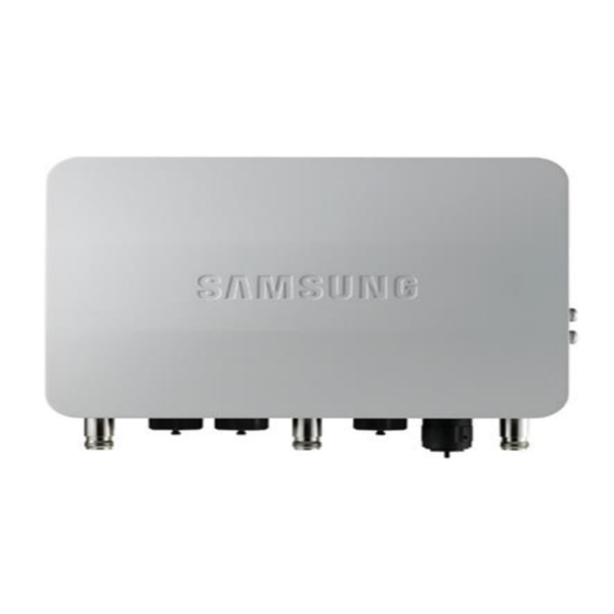
WEA453e Installation Manual Version 1.0 Interface The interface and connections for the Outdoor AP are as follows: ANT_1 ANT_3 ANT_2 Ground Terminal DC 48 V CONSOLE Figure 2. Outdoor AP Interface Samsung Electronics America Page 16 of 117... -
Page 17: System Specifications
The environmental conditions required for the Outdoor AP are as follows: Table 4. Environmental Conditions Item Specifications Operating Temperatures -40°C to 55°C Humidity 5-100 % (non-condensing) Cooling Method Ambient air Resistance to Dust/Water IP66 & IP67 Samsung Electronics America Page 17 of 117... -
Page 18: Installation Safety Procedures
Be careful not to damage the cable installation area during the cleaning process. Be careful to avoid any contact with the power supply by any foreign substance while cleaning up which may result in a product malfunction. Samsung Electronics America Page 18 of 117... -
Page 19: Installation Tools
These basic tools are subject to change based on the actual conditions of the installation site. Be prepared with any other necessary tools, such as a protractor, compass, ladder, and any additional safety or cleaning equipment that may be required in accordance with the site conditions. Samsung Electronics America Page 19 of 117... -
Page 20: Chapter 2. System Installation
The installation procedure for the Outdoor AP is as follows: System Arrangement Foundation Procedure Marking and Drilling Moving the Components Unpacking and Transporting Unpacking the Components Mounting the System Leveling the System Figure 3. Installation Procedure for the Outdoor AP Samsung Electronics America Page 20 of 117... -
Page 21: Foundation Procedure
800 mm or further Side 300 mm or further Top/Bottom 1,000 mm or further Unit: mm 61.5 [Front View] [Front View] [Top View] [Top View] Outdoor AP Adapter Figure 4. Wall Type Arrangement Samsung Electronics America Page 21 of 117... -
Page 22: Figure 5. Pole Type Arrangement
Figure 5. Pole Type Arrangement The top view of the above image is used when the diameter of the pole is 101.6 mm, however the measurement may differ depending on the pole diameter. Samsung Electronics America Page 22 of 117... -
Page 23: Carrying And Unpacking
Unpack the internal packaging after arranging the components in their respective installation positions. Do not recycle the unused materials. Dispose of the packaging materials in according with the local waste disposal regulations. Samsung Electronics America Page 23 of 117... -
Page 24: Mounting The System
2) Fix the unit bracket to the Outdoor AP by matching up each hole and screwing in the 4 torx screws (WSP). Unit Bracket Torx Screws (WSP) Figure 6. Assembling the Unit Bracket Samsung Electronics America Page 24 of 117... -
Page 25: Figure 7. Assembling The Dipole Antennas (1)
Required Tool 2) Connect the 3 dipole antennas to the Outdoor AP connectors (ANT1, ANT2, and ANT3). RF Antenna Port (N Type-Female) N Type-male connector Dipole Antenna Figure 7. Assembling the Dipole Antennas (1) Samsung Electronics America Page 25 of 117... -
Page 26: Figure 8. Assembling The Dipole Antennas (2)
6) Tie both ends of the insulating tape using cable ties to make sure they do not become unwrapped. Insulating Tape Insulating Tape Insulating Tape Figure 8. Assembling the Dipole Antennas (2) Samsung Electronics America Page 26 of 117... -
Page 27: Figure 9. Assembling The Dipole Antennas (3)
WEA453e Installation Manual Version 1.0 Butyl Tape Butyl Tape Butyl Tape Insulating Tape Butyl Tape Insulating Tape Cable Tie Figure 9. Assembling the Dipole Antennas (3) Samsung Electronics America Page 27 of 117... -
Page 28: Wall Mounting
Place the system in the appropriate place and then mark the locations to fix the anchor bolts using a pen. Unit: mm 63.9 Plastic Anchor Hole (Ф 5) Figure 10. Marking the Outdoor AP Samsung Electronics America Page 28 of 117... -
Page 29: Figure 11. Marking The Adapter
2) Draw a horizontal line between the marked holes. 3) Verify the horizontal line is correct by using a spirit level. If it is not level, then adjust the marked points accordingly. Samsung Electronics America Page 29 of 117... -
Page 30: Figure 12. Marking Example
Table 9. Drill Bit and Hole Depth for Anchor Bolts Item Anchor Bolt Drill Bit Hole Depth Outdoor AP 6 mm 30 mm [Cross Section of a Hole] 6 mm 30 mm * Remove any foreign substances from inside the drilled hole. Samsung Electronics America Page 30 of 117... -
Page 31: Figure 13. Drilling Example
1 EA M6 × 30L Plastic Anchors 4 EA M4 × 25L Tapping Screws 4 EA Regulated Torque Value M4 Tapping Screw 9.52-14.28 kgf·cm Required Tools Drill, Hammer, Torque Driver, and Spirit Level Samsung Electronics America Page 31 of 117... -
Page 32: Figure 14. Mounting The Mount Bracket On The Wall (1)
WEA453e Installation Manual Version 1.0 2) Insert the plastic anchors into the drilled holes on the wall. Plastic Anchor Wall 90˚ 90˚ Figure 14. Mounting the Mount Bracket on the Wall (1) Samsung Electronics America Page 32 of 117... -
Page 33: Figure 15. Mounting The Mount Bracket On The Wall (2)
Version 1.0 3) Align the mount bracket with the plastic anchors and firmly attach it using the screws. Plastic Anchor Tapping Screw Mount Bracket Figure 15. Mounting the Mount Bracket on the Wall (2) Samsung Electronics America Page 33 of 117... -
Page 34: Figure 16. Mounting The Outdoor Ap On The Wall (1)
2) Hang the unit bracket with the groove aligned with the screws temporarily fixed to the mount bracket. Mount Bracket Unit Bracket Groove M4 Torx Screw (WSP) Figure 16. Mounting the Outdoor AP on the Wall (1) Samsung Electronics America Page 34 of 117... -
Page 35: Figure 17. Mounting The Outdoor Ap On The Wall (2)
M4 Torx Screw (WSP) Figure 17. Mounting the Outdoor AP on the Wall (2) 4) Mount the top part using a screw. M4 Torx Screw (WSP) Figure 18. Mounting the Outdoor AP on the Wall (3) Samsung Electronics America Page 35 of 117... -
Page 36: Figure 19. Mounting The Adapter (1)
Required Tools Drill, Hammer, Torque Driver, and Spirit Level 2) Insert the plastic anchors into the drilled holes on the wall. Plastic Anchor 34 mm 90˚ Wall 90˚ Figure 19. Mounting the Adapter (1) Samsung Electronics America Page 36 of 117... -
Page 37: Figure 20. Mounting The Adapter (2)
WEA453e Installation Manual Version 1.0 3) Attach the adapter to the plastic anchors using screws. Plastic Anchor Tapping Screw Adapter Figure 20. Mounting the Adapter (2) Samsung Electronics America Page 37 of 117... - Page 38 WEA453e Installation Manual Version 1.0 When mounting the wall-type adapter, place the adapter directly on the wall without using the adapter mount bracket. Samsung Electronics America Page 38 of 117...
-
Page 39: Mounting To A Pole
The 2 M4 Torx Screws (WSP) should be tightened on the left and right sides of the bracket. 2) Attach the mount bracket to the pole using the metal bands. Pole Mount Bracket Metal band Figure 21. Mounting the Outdoor AP on a Pole (1) Samsung Electronics America Page 39 of 117... -
Page 40: Figure 22. Mounting The Outdoor Ap On A Pole (2)
Mount Bracket Figure 22. Mounting the Outdoor AP on a Pole (2) 4) Tighten each screw on both sides. M4 Torx Screw (WSP) Figure 23. Mounting the Outdoor AP on a Pole (3) Samsung Electronics America Page 40 of 117... -
Page 41: Figure 24. Mounting The Outdoor Ap On A Pole (4)
‘+’ Driver The tightening components that are used for mounting the adapter to a pole must be stainless steel (STS 304). If this is not followed, the components can become corroded and rust. Samsung Electronics America Page 41 of 117... -
Page 42: Figure 25. Mounting The Adapter On A Pole (1)
Version 1.0 2) Align the adapter screw holes with the Adapter bracket holes and secure the adapter using the 4 screw (WSP). Adapter Bracket ‘+’Screw(WSP) Figure 25. Mounting the Adapter on a Pole (1) Samsung Electronics America Page 42 of 117... -
Page 43: Figure 26. Mounting The Adapter On A Pole (2)
WEA453e Installation Manual Version 1.0 3) Secure the adapter mount bracket to the pole using the metal band. Pole Adapter Bracket Metal band tightening part Figure 26. Mounting the Adapter on a Pole (2) Samsung Electronics America Page 43 of 117... -
Page 44: Leveling The System
If there is a modulator in the system, adjust the height of it. [Horizontal Leveling] [Vertical Leveling] Figure 27. Using a Spirit Level on a Wall Mount (1) Samsung Electronics America Page 44 of 117... -
Page 45: Figure 28. Using A Spirit Level On A Wall Mount (2)
WEA453e Installation Manual Version 1.0 [Vertical Leveling] Figure 28. Using a Spirit Level on a Wall Mount (2) [Horizontal Leveling] [Vertical Leveling] Figure 29. Using a Spirit Level on a Pole Mount (1) Samsung Electronics America Page 45 of 117... -
Page 46: Figure 30. Using A Spirit Level On A Pole Mount (2)
WEA453e Installation Manual Version 1.0 [Vertical Leveling] Figure 30. Using a Spirit Level on a Pole Mount (2) Samsung Electronics America Page 46 of 117... -
Page 47: Chapter 3. Cables Connect
Connecting the System Ground Cable Connecting the System Power Cable Connecting a Power Cable Connecting a PoE Cable Connecting an Ethernet Cable Connecting an Interface Cable Connecting the Patch Antenna Cable Figure 31. Connecting the System Cables Samsung Electronics America Page 47 of 117... -
Page 48: Figure 32. Procedure For Connecting The Cables
Select a minimum cable length within a range that does not affect cable installation or maintenance. The cable must be installed in a location where it will not be damaged by external factors, such as power lines, flooding, footpaths, etc. Samsung Electronics America Page 48 of 117... -
Page 49: Table 16. Minimum Cable Bend Radius Allowed
Table 16. Minimum Cable Bend Radius Allowed Type Minimum Allowed Bend Radius Description F-GV/F-CV/FR-8 8 times the external diameter of the 0.6/1 KV Cable cable UTP/FTP/S-FTP cable 4 times the external diameter of the PVC/LSZH, 4 Pair cable Samsung Electronics America Page 49 of 117... - Page 50 Keep the cables straight where the connectors are linked. Prevent a bad connection from occurring as a result of tension in the connection area. Samsung Electronics America Page 50 of 117...
- Page 51 Also, keep the DC power or data transmitting cable away from the AC power cable to avoid any electromagnetic induction. Operators must have full knowledge of connecting cables, such as installing/ binding cables, before working on the cables. Samsung Electronics America Page 51 of 117...
-
Page 52: Cable Configuration
[Patch Antenna] 5) Antenna Cable 5) Antenna Cable [Outdoor AP] [MGB] [MGB] [PoE Switch] [Switch or Router] 2) Power Cable Assembly (AC) AC Distribution Box [AC/DC Adaptor] Figure 33. Outdoor AP Connection Cables Samsung Electronics America Page 52 of 117... -
Page 53: Table 17. Outdoor Ap Connection Cables
PoE Switch 3) PoE Cable : S-FTP Cat.6, 4 Pair, ø8.1~ ø8.5 Switch or Router 4) Ethernet Cable : S-FTP Cat.6, 4 Pair, ø8.1~ ø8.5 Patch Antenna 5) Antenna Cable : Antenna Cable Assembly Samsung Electronics America Page 53 of 117... -
Page 54: Connecting A Ground Cable
Φ 10 mm/Green/50 mm (Spec/Color/Length) Pressure Terminal Check the MGB standards for the field and have the pressure terminal ready. Outdoor AP 4 mm , 2 holes, hole diameter: 6.4 mm, hole distance: 16 mm Samsung Electronics America Page 54 of 117... -
Page 55: Figure 34. Connecting A Ground Cable To The Outdoor Ap (1)
Fastening components, such as the pressure terminal or cables, must meet the UL or equivalent standards requirements. Ex) Manufacturer: Panduit Outdoor AP: 4 mm Pressure Terminal (LCD10-14A-L) For information on how to assemble the pressure terminal and the heat shrink tube, see ANNEX C. Samsung Electronics America Page 55 of 117... -
Page 56: Figure 35. Connecting A Ground Cable To The Outdoor Ap (2)
Arrestor M4 Screw/1 EA (Installed on the arrestor) Regulated Torque M4 Screw 9.52-14.28 kgf·cm Value Required Tools Cable Cutter, Wire Stripper, Crimper, Heating Gun, Torque Driver (+), Torque Wrench, and Nipper Samsung Electronics America Page 56 of 117... -
Page 57: Figure 36. Connecting A Ground Cable To The Outdoor Ap (3)
Arrestor-1 using the fastening components. Fastening components, such as the pressure terminal or cables, must meet the UL or equivalent standards requirements. Ex) Manufacturer: Panduit Arrestor: 4 mm Pressure Terminal (S10-10R-Q) Samsung Electronics America Page 57 of 117... -
Page 58: Figure 37. Connecting A Ground Cable To The Arrestor (1)
WEA453e Installation Manual Version 1.0 Arrestor-1 Arrestor-2 Pressure Terminal M4 Screw Heat Shrink Tube (Green) Ground Cable Figure 37. Connecting a Ground Cable to the Arrestor (1) Samsung Electronics America Page 58 of 117... -
Page 59: Figure 38. Connecting A Ground Cable To The Arrestor (2)
3) After assembling Arrestor-2 and Arrestor-3 using a pressure terminal and a heat shrink tube, secure only Arrestor-1 using the fastening components. Arrestor-3 Arrestor-2 Arrestor-1 Arrestor-2 Arrestor-2 Pressure Terminal Heat Shrink Tube (Green) M4 Screw Figure 38. Connecting a Ground Cable to the Arrestor (2) Samsung Electronics America Page 59 of 117... -
Page 60: Figure 39. Connecting A Ground Cable To The Arrestor (3)
4) Assemble Arrestor-3 with a pressure terminal and a heat shrink tube, then connect it to the MGB. Arrestor-1 Arrestor-2 Arrestor-3 Arrestor-3 Arrestor-3 Pressure Terminal Heat Shrink Tube (Green) M4 Screw Figure 39. Connecting a Ground Cable to the Arrestor (3) Samsung Electronics America Page 60 of 117... -
Page 61: Figure 40. Connecting A Ground Cable To The Patch Antenna
Screw Standard: M4 × L8 (washer included)/Regulated Torque Value: 6.0 kgf·cm Patch Antenna M4 × 8L Screw Figure 40. Connecting a Ground Cable to the Patch Antenna Samsung Electronics America Page 61 of 117... -
Page 62: Connecting A Power Cable
Check the output port standards for the field and prepare the connector. Outdoor AP - System Side: DY5F1203PNFL[JONHON] - Cable Side: DY5T1203SNF[JONHON] Required Tools Cable Cutter, Wire Stripper, Crimper, Heating Gun, Torque Driver (+), Torque Wrench, and Nipper Samsung Electronics America Page 62 of 117... -
Page 63: Table 21. Power Cable/Connector Pin Map
WEA453e Installation Manual Version 1.0 Item Description Table 21. Power Cable/Connector Pin Map Power Connector Pin No. Description Color White NC (No Connection) Green 48 VDC Black [System-Side Connector: DY5F1203PNFL-04] [Cable-Side Connector: DY5T1203SNF] Samsung Electronics America Page 63 of 117... -
Page 64: Figure 42. Connecting A Power Cable (1)
Cable Gland 2) Install the DC cable from the Outdoor AP to the AC distribution box. [Outdoor AP] Power Cable-2 Power Cable-1 AC Distribution Box AC/DC Adapter Figure 42. Connecting a Power Cable (1) Samsung Electronics America Page 64 of 117... -
Page 65: Figure 43. Connecting A Power Cable (2)
7) Take the connector body in your left hand and turn the coupling nut with your right hand in a clockwise direction until the lock clicks. If excessive force is applied to the coupling nut while turning it, the connector can become damaged. Samsung Electronics America Page 65 of 117... -
Page 66: Figure 44. Connecting A Power Cable (3)
Figure 44. Connecting a Power Cable (3) Do not apply excessive force to pull on the cable. Do not bend the cable to exceed the allowed bend radius. Do not twist the cable. Samsung Electronics America Page 66 of 117... -
Page 67: Connecting An Interface Cable
Use a waterproof cap, rubber packing, or other finishing materials. - Port or connection with a cable installed: After installing the cable, use a pressed sponge, rubber packing, or silicon to remove any gaps in the port or the connection. Samsung Electronics America Page 67 of 117... -
Page 68: Figure 45. Connecting The Poe Cable (1)
WEA453e Installation Manual Version 1.0 2) Install the PoE cable from the PoE switch to the Outdoor AP PoE port. [Outdoor AP] PoE Cable PoE Switch Figure 45. Connecting the PoE Cable (1) Samsung Electronics America Page 68 of 117... -
Page 69: Figure 46. Connecting The Poe Cable (2)
RJ-45 plug faces down and listen for a clicking sound. PoE Port RJ-45 Plug Fixing Tube Shell PoE Cable RJ-45 Latch Insert as the RJ-45 Latch face down Figure 46. Connecting the PoE Cable (2) Samsung Electronics America Page 69 of 117... -
Page 70: Figure 47. Connecting The Poe Cable (3)
5) Push the shell against the Outdoor AP PoE connector. 6) Straighten the cable and fasten the shell by turning it clockwise. Fixing Tube Shell Shell Figure 47. Connecting the PoE Cable (3) Samsung Electronics America Page 70 of 117... -
Page 71: Figure 48. Connecting The Poe Cable (4)
WEA453e Installation Manual Version 1.0 7) Fasten it completely until the white belt on the connector can no longer be seen. White Belt Figure 48. Connecting the PoE Cable (4) Samsung Electronics America Page 71 of 117... -
Page 72: Connecting A Lan Cable
Gigabit Ethernet Tx/Rx0-+ White/Green Gigabit Ethernet Tx/Rx1+ Blue Gigabit Ethernet Tx/Rx2+ White/Blue Gigabit Ethernet Tx/Rx2-+ Green Gigabit Ethernet Tx/Rx1-+ White/Brown Gigabit Ethernet Tx/Rx3+ Brown Gigabit Ethernet Tx/Rx3-+ Shell Shield Shield RJ-45 Plug Fixing Tube Shell Samsung Electronics America Page 72 of 117... -
Page 73: Figure 49. Connecting A Lan Cable (1)
2) Install the LAN cable from the switch (or router) to the Outdoor AP LAN port. [Outdoor AP] LAN Cable Switch or Router Figure 49. Connecting a LAN Cable (1) Samsung Electronics America Page 73 of 117... -
Page 74: Figure 50. Connecting A Lan Cable (2)
RJ-45 plug faces down and listen for a clicking sound. LAN Port RJ-45 Plug Fixing Tube Shell LAN Cable RJ-45 Latch Insert as the RJ-45 Latch face down Figure 50. Connecting a LAN Cable (2) Samsung Electronics America Page 74 of 117... -
Page 75: Figure 51. Connecting A Lan Cable (3)
5) Push the shell against the Outdoor AP PoE connector. 6) Straighten the cable and fasten the shell by turning it clockwise. Fixing Tube Shell Shell Figure 51. Connecting a LAN Cable (3) Samsung Electronics America Page 75 of 117... -
Page 76: Figure 52. Connecting A Lan Cable (4)
WEA453e Installation Manual Version 1.0 7) Fasten it completely until the white belt on the connector can no longer be seen. White Belt Figure 52. Connecting a LAN Cable (4) Samsung Electronics America Page 76 of 117... -
Page 77: Connecting The Arrestors
3 EA Connectors Linked to the Outdoor AP N Type-Male Linked to the Patch Antenna N Type-Female Regulated Torque Value N Type 16.5-18.1 kgf·cm Required Tool Torque Wrench [Outdoor AP Side] [Patch Antenna Side] Samsung Electronics America Page 77 of 117... -
Page 78: Figure 53. Connecting The Arrestors (1)
4) Wrap the insulating tape in two or more layers of butyl tape, covering all of the insulating tape and up to 10-20 mm below the insulated area. 5) Wrap over the butyl tape area with two or more layers of insulating tape in the same manner. Samsung Electronics America Page 78 of 117... -
Page 79: Figure 54. Connecting The Arrestors (2)
Version 1.0 6) Tie both ends of the insulating tape using cable ties to make sure they do not become unwrapped. Insulating Tape Insulating Insulating Tape Tape Figure 54. Connecting the Arrestors (2) Samsung Electronics America Page 79 of 117... -
Page 80: Figure 55. Connecting The Arrestors (3)
WEA453e Installation Manual Version 1.0 Butyl Tape Butyl Tape Butyl Tape Insulating Tape Butyl Tape Insulating Tape Cable Tie Figure 55. Connecting the Arrestors (3) Samsung Electronics America Page 80 of 117... -
Page 81: Connecting The Patch Antenna Cables
Cable Cutter, Wire Stripper, Nipper, Torque Wrench, Spanner, Utility Knife, Soldering Iron, and Lead 2) Connect the cables from the Outdoor AP arrestor to the patch antenna. [Patch Antenna] Patch Antenna Cable Figure 56. Connecting the Patch Antenna Cables (1) Samsung Electronics America Page 81 of 117... -
Page 82: Figure 57. Connecting The Patch Antenna Cables (2)
4) Wrap the insulating tape in two or more layers of butyl tape, covering all of the insulating tape and up to 10-20 mm below the insulated area. 5) Wrap over the butyl tape area with two or more layers of insulating tape in the same manner. Samsung Electronics America Page 82 of 117... -
Page 83: Figure 58. Connecting The Patch Antenna Cables (3)
7) Tie both ends of the insulating tape using cable ties to make sure they do not become unwrapped. Insulating Tape Insulating Tape Insulating Tape Figure 58. Connecting the Patch Antenna Cables (3) Samsung Electronics America Page 83 of 117... -
Page 84: Figure 59. Connecting The Patch Antenna Cables (4)
WEA453e Installation Manual Version 1.0 Butyl Tape Butyl Tape Butyl Tape Insulating Insulating Tape Tape Butyl Tape Cable Tie Figure 59. Connecting the Patch Antenna Cables (4) Samsung Electronics America Page 84 of 117... -
Page 85: Connecting The Patch Antenna Cables (Outdoor Ap)
Unpack the patch antenna package and confirm all of the following components are included. [Patch Antennas] [Pipe Clamp] [Wall Clamp] [M4 × L20 tapping [Impact anchor 5 EA] [M4 × L8 screw 5 EA] type 1 screw 5 EA] Figure 60. Patch Antenna Package Components Samsung Electronics America Page 85 of 117... - Page 86 Make sure that all of the necessary components are included and prepared before installing. Always make sure the patch antenna cable is facing down when installing it outside or on a pipe. Only trained service personnel can install or remove the patch antenna. Samsung Electronics America Page 86 of 117...
-
Page 87: Figure 61. Installing On A Wall
3) Screw the M4 × L20 screws into the holes of the patch antenna to secure the patch antenna to the impact anchors. 4) Return the screw caps to the mounted patch antenna. A wall where 221.3 mm 221.3 mm Figure 61. Installing on a Wall Samsung Electronics America Page 87 of 117... -
Page 88: Figure 62. Installing On A Pipe
(Torque 80.0 kgf.cm). 3) Unscrew the M4 bolts, adjust the angle of the patch antenna (to up/down, left/right), and then tighten the M4 bolts again. M4 bolts Figure 62. Installing on a Pipe Samsung Electronics America Page 88 of 117... - Page 89 5) Leave 2.3-3 mm of the screws out from the wall when screwing the 2 M4 × L20 screws into the impact anchors. 6) Hook the keyholes of the bracket on the two screw heads, and then secure the patch antenna by pulling it down towards the cables. Samsung Electronics America Page 89 of 117...
-
Page 90: Figure 63. Installing On A Wall Using Brackets
WEA453e Installation Manual Version 1.0 Figure 63. Installing on a Wall Using Brackets Samsung Electronics America Page 90 of 117... - Page 91 3) Take the caps off of the patch. Keep the caps. 4) Use the M4 × L20 screws to screw the patch antenna and the plate onto the ceiling securely. 5) Return the screw caps to the mounted patch antenna. Samsung Electronics America Page 91 of 117...
-
Page 92: Figure 64. Installing On A Ceiling
1-M4 screw Ceiling Steel plate Ceiling Ceiling Figure 64. Installing on a Ceiling Refer to the Outdoor AP installation manual for instructions on how to connect the patch antenna cable to the Outdoor AP. Samsung Electronics America Page 92 of 117... -
Page 93: Chapter 4. Inspecting The Installation Status
On-site Inspection Performing the Inspection checklist Inspection Checklist/ Reporting the Results Corrective Actions Complying with Corrective Action Inspecting Compliance Results Reporting Final Results and Prevention Plans Figure 65. Procedure for Inspecting the Installation Status Samsung Electronics America Page 93 of 117... -
Page 94: Table 28. Inspection Checklist
Maintenance and the horizontal/vertical equipment and arrangement status. mechanical parts Leveling state of Inspection of the horizontal/vertical equipment and status (using a spirit level). mechanical parts Tightened status and Check with the naked eye and use Samsung Electronics America Page 94 of 117... - Page 95 Other Data Cable standards Check the cable standards are correct Cables for each purpose. Cable installation and Check the damage/installed route/ binding status bending radius of cables and the Samsung Electronics America Page 95 of 117...
- Page 96 Check the status of the cable tray, duct, status and other installation items. Clean-up state for Check for any disposed materials/items/ inside/outside and the packing materials and the overall clean- surrounding area of up status. the system. Opinions Samsung Electronics America Page 96 of 117...
-
Page 97: Annex A
7) Cut the shield leaving a 5 mm of 8) Arrange the cable in reference to 9) Cut the cable to make it 12 mm the pin map. long. Figure 66. Assembling the RJ-45 Connector (Shield Type) (1) Samsung Electronics America Page 97 of 117... -
Page 98: Figure 67. Assembling The Rj-45 Connector (Shield Type) (2)
13) Compress the jack using the tool. 14) Move the RJ-45 cap to the connector side and compress the marking tube to finish the assembly. Figure 67. Assembling the RJ-45 Connector (Shield Type) (2) Samsung Electronics America Page 98 of 117... -
Page 99: Finishing The Connector Connection Part By Tape
Wrap the tape with the half of the tape width is overlapped. (For both insulation tape and butyl tape) Overlap area of tape Tape Width Figure 68. Check Items for Finishing the Connector Connection Part Samsung Electronics America Page 99 of 117... -
Page 100: Annex B
The following must be available to connect a pressure terminal to a cable. [Cable] [Pressure Terminal] [Heat Shrink Tube] [Cable Cutter] [Wire Stripper] [Handheld Compressor] [Hydraulic Press] [Marking Pen] [Cutter Blade] [Steel Ruler] [Scissors] [Heat Gun] Figure 69. Preparations Samsung Electronics America Page 100 of 117... -
Page 101: B.2 Pressure Reference Table
31~47 mm Hydraulic 48~63 mm Hydraulic 64 mm or more Unit: mm [1-spot] [2-spot] [3-spot] Copper Tube Starting Middle of Copper Tube Arbitrary Fixing Reference Points [4-spot] Figure 70. Pressure Reference Drawing (Handheld Compressor) Samsung Electronics America Page 101 of 117... -
Page 102: Figure 71. Pressure Reference Drawing (Hydraulic Compressor)
Reference Points Figure 71. Pressure Reference Drawing (Hydraulic Compressor) Table 30. Compressor Specifications per Cable Thickness Press Size Cable Size (mm Large Handheld Hydraulic Press (IZUMI Small Handheld Press Press (AK-38, 100) Hexagonal Dies) Samsung Electronics America Page 102 of 117... - Page 103 WEA453e Installation Manual Version 1.0 Press Size Cable Size (mm Large Handheld Hydraulic Press (IZUMI Small Handheld Press Press (AK-38, 100) Hexagonal Dies) 95~300 Samsung Electronics America Page 103 of 117...
-
Page 104: B.3 Assembling Pressure Terminal
2) Adjust the length of a cutter blade according to the sheath thickness of the cable. 3) Push the clamp with a thumb according to the cable size to secure a space for the cable. Figure 73. Stripping Cable Sheath (2) Samsung Electronics America Page 104 of 117... -
Page 105: Figure 74. Stripping Cable Sheath (3)
6) Push the lever of the stripper to the right to turn its blade at 90°. Figure 75. Stripping Cable Sheath (4) 7) Move the stripper up to the end of cable while maintaining the stripper to be perpendicular to the cable. Figure 76. Stripping Cable Sheath (5) Samsung Electronics America Page 105 of 117... -
Page 106: Figure 77. Stripping Cable Sheath (6)
- Make sure that the cutter blade goes into the cable sheath completely. - Rotate the wire stripper perpendicularly to the cable. Samsung Electronics America Page 106 of 117... -
Page 107: Figure 78. Fixing Pressure Terminal_Handheld Compressor (1)
3) Insert the pressure terminal to the selected hole. 4) Fix the pressure terminal and cable temporarily so the position can be changed later by pressing the compressor. Figure 80. Fixing Pressure Terminal_Handheld Compressor (3) Samsung Electronics America Page 107 of 117... -
Page 108: Figure 81. Fixing Pressure Terminal_Handheld Compressor (4)
Figure 81. Fixing Pressure Terminal_Handheld Compressor (4) 6) Separate the pressure terminal from the handheld compressor. Press down the handle of compressor until a clicking sound is heard to be unlocked. Figure 82. Fixing Pressure Terminal_Handheld Compressor (5) Samsung Electronics America Page 108 of 117... -
Page 109: Figure 83. Fixing Pressure Terminal_Hydraulic Press (1)
25 mm (DIN) Fixing Pressure Terminal (Hydraulic Press) 1) Among the dies of the hydraulic press, select one that fits to the pressure terminal. Dies Hydraulic Press Figure 83. Fixing Pressure Terminal_Hydraulic Press (1) Samsung Electronics America Page 109 of 117... -
Page 110: Figure 84. Fixing Pressure Terminal_Hydraulic Press (2)
3) Insert the pressure terminal into the pressing area and fix it slightly by aligning it to the end of cable sheath. Figure 85. Fixing Pressure Terminal_Hydraulic Press (3) 4) Move the compressor lever up and down to press the pressure terminal firmly. Figure 86. Fixing Pressure Terminal_Hydraulic Press (4) Samsung Electronics America Page 110 of 117... -
Page 111: Figure 87. Fixing Pressure Terminal_Hydraulic Press (5)
Version 1.0 5) Turn the top compressing lever clockwise and then push it down. When the pressing area of compressor is loosened, remove the pressure terminal. Figure 87. Fixing Pressure Terminal_Hydraulic Press (5) Samsung Electronics America Page 111 of 117... - Page 112 Therefore, refer to the user manual enclosed with the product. The specifications and cautions of a hydraulic press described in this manual are as follows: - Vender: IZUMI - Model: IZUMI-EP-510B - Specification: Circular 32~160 (SQ) Hex 14~325 (SQ) Samsung Electronics America Page 112 of 117...
-
Page 113: Figure 88. Assembling Heat Shrink Tube (1)
4) Rotate a heat gun 360° to apply heat evenly to shrink the tube. (Because the pressure terminal and the cable is hot due to the heat of a heating gun, be careful not to have a burn.) Figure 89. Assembling Heat Shrink Tube (2) Samsung Electronics America Page 113 of 117... -
Page 114: Annex C
Torque value can be different, defending on the material, characteristic and specification of the equipment and fastener. Make sure to check the proper torque value for each specification of the equipment and fastener. Samsung Electronics America Page 114 of 117... -
Page 115: Figure 90. Outdoor Ap Selection Guide
Brackets included Selection In a Unit Box Unit Bracket x1 Thick Thin Mount Bracket x1 Thin or Screws Thick 50 – 150mm 150 – 250mm WDS-AMB100 WDS-AMB200 Figure 90. Outdoor AP Selection Guide Samsung Electronics America Page 115 of 117... - Page 116 WEA453e Installation Manual Version 1.0 ABBREVIATION Access Point American Wire Gauge Electromagnetic Compatibility Local Area Network Main Ground Bar Power over Ethernet Radio Frequency S-FTP Screened Foiled Twisted Pair Page 116 of 117 Samsung Electronics America...
-
Page 117: Samsung Electronics America
WEA453e Installation Manual Version 1.0 WEA453e AP Installation Manual Copyright 2015 Samsung Electronics America All rights reserved. No part of this manual may be reproduced in any form or by any means-graphic, electronic or mechanical, including recording, taping, photocopying or information retrieval systems –...
Need help?
Do you have a question about the WEA453e AP and is the answer not in the manual?
Questions and answers