
Related Manuals for Samsung 310 5G CPE


Summary of Contents for Samsung 310 5G CPE
- Page 1 310 5G CPE Indoor Installation Manual Describes the product installation and requirement procedure. Document Version 2.0 June 2018 Document Number: N/A...
- Page 2 To the extent permitted by law no liability (including liability to any person by reason of negligence) will be accepted by SAMSUNG Electronics Co., Ltd., its subsidiaries or employees for any direct or indirect loss or damage caused by omissions from or inaccuracies in this document.
-
Page 3: Table Of Contents
Confidential Contents Preface Conventions in this Document ......................vi New and Changed Information ...................... vii Revision History ..........................vii Organization of This Document ..................... vii Related Documentation ......................... vii Personal and Product Safety ......................viii Equipment Markings ........................ix Chapter 1 Before Installation System View and Interface ....................... - Page 4 Confidential List of Figures Figure 1. CPE DU External Interface ........................ 2 Figure 2. Power Cord and Power Supply ......................2 Figure 3. Procedure to Install the Indoor CPE ....................7 Figure 4. Indoor CPE Package Contents ......................8 Figure 5. Indoor CPE Window Frame Installation Step 1 ................
- Page 5 Confidential List of Tables Table 1. 5G Indoor CPE Power Cord and Power Supply Specifications ............3 Table 2. 5G Indoor CPE Key Specifications ....................4 Table 3. Basic Installation Tools ........................6 Table 4. Requirement to Fix Indoor CPE on Window Frame ............... 12 Table 5.
-
Page 6: Preface
Preface This manual describes how to install the ICL Indoor CPE (Model: SFG-D0100) on a window frame bracket including how to connect cables. Conventions in this Document Samsung Networks product documentation uses the following conventions. Symbols Symbol Description Indicates a task. -
Page 7: New And Changed Information
Confidential Preface New and Changed Information This section describes information that has been added/ changed since the previous publication of this manual. Revision History The following table lists all versions of this document. Document Number Product/Software Document Publication Date Remarks Version Version Indoor ICL 5G... -
Page 8: Personal And Product Safety
Confidential Preface Personal and Product Safety This product safety information includes European directives, which you must follow. If these do not apply in your country, please follow similar directives that do apply in your country. Proposition 65 (US Only) State of California Proposition 65 Warning (US only) WARNING: This product contains chemicals known to the State of California to cause cancer and birth defects or other reproductive harm. -
Page 9: Equipment Markings
Confidential Preface Fire The product is powered from an AC supply. To protect against fire, the equipment is fused. Environment The product must be operated in an environment with the specified relative humidity and ambient temperature ranges. Keep all liquids away from the equipment as accidental spillage can cause severe damage. -
Page 10: Chapter 1 Before Installation
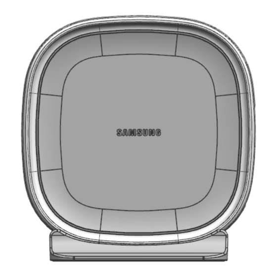
Chapter 1 Before Installation System View and Interface Indoor CPE View The view of the Indoor CPE is as follows. 5G Indoor CPE Installation Manual Copyright © 2018, All Rights Reserved. -
Page 11: Indoor Cpe External Interface
Confidential Indoor CPE External Interface The external interface structure of the Indoor CPE is as follows. Figure 1. CPE DU External Interface Factory Reset LED(Power) LED(Signal) nSIM LED(Connection) LED(Alarm) POWER Indoor CPE Power Cord and Power Supply The following figure shows the connectivity of the power cord and power supply. Figure 2. -
Page 12: Table 1. 5G Indoor Cpe Power Cord And Power Supply Specifications
Confidential Table 1. 5G Indoor CPE Power Cord and Power Supply Specifications Item Specification Power Cord Length 1.8 meters Color Black Power Supply Input Voltage AC100~240 VAC @ 50/60 Hz Output Voltage 12 VDC (± 5 %) Operating Temperature 0~50°C Operating Humidity 5~90 % 5G Indoor CPE Installation Manual... -
Page 13: Specifications
Confidential Specifications Key Specifications The following table shows the key specifications of the Indoor CPE. Table 2. 5G Indoor CPE Key Specifications Item Specifications Technology 5G (Follows Verizon 5GTF's latest version) Operating Frequency 27.5 GHz ~ 28.35 GHz Channel Bandwidth 100 MHz Operating Bandwidth 100 MHz x 8 Carrier... -
Page 14: Cautions For Installation
Confidential Cautions for Installation Observe the following safety instructions when installing the system. Before Installing The system must be installed close to a window or wall to face a guided direction to a 5G signal. The location of the CPE allows at least 20 cm (about 8 inches) between the unit and persons to be compliance with FCC RF exposure guidelines. -
Page 15: Installation Tools
Confidential Installation Tools The basic tools for installation are listed in the table below. The additional tools required for each site need to be identified and prepared during a site survey before starting installation. Table 3. Basic Installation Tools Name Specification Remarks Basic tool... -
Page 16: Installing System
Chapter 2 Installing System This chapter describes the procedures to install the system. Installation Procedure The procedure to install the RFA is as follows. Figure 3. Procedure to Install the Indoor CPE Fixing indoor CPE on window bracket Plug in the Power to CPE Fixing CPE on window bracket Ethernet cable into LAN port of CPE Power Up the indoor CPE... -
Page 17: Transporting And Unpacking
Confidential Transporting and Unpacking This section describes the work to unpack cabinets and other components and transport them to the location to be installed. Bringing in Items Bring in items, taking care of the following: • When carrying the system, tighten the system firmly: do not exceed the proper vibration level from 1 to 500 Hz. -
Page 18: Indoor Cpe Installation
Confidential Indoor CPE Installation This section describes the procedures to fix the indoor CPE on the window frame bracket. The Indoor CPE bottom shows the proper orientation of the CPE side facing outside the window. Make sure to check the correct orientation while installing. The Indoor CPE must be fixed vertically as depicted in the following guidelines. -
Page 19: Figure 5. Indoor Cpe Window Frame Installation Step 1
Confidential Figure 5. Indoor CPE Window Frame Installation Step 1 Figure 6. Indoor CPE Window Frame Installation Step 2 5G Indoor CPE Installation Manual Copyright © 2018, All Rights Reserved. -
Page 20: Figure 7. Indoor Cpe Window Frame Installation Step 3
Confidential Figure 7. Indoor CPE Window Frame Installation Step 3 Figure 8. Indoor CPE Window Frame Installation Step 4 5G Indoor CPE Installation Manual Copyright © 2018, All Rights Reserved. -
Page 21: Figure 9. Indoor Cpe Window Frame Installation Step 5
Confidential Figure 9. Indoor CPE Window Frame Installation step 5 Figure 10. Indoor CPE Window Frame Installation step 6 Table 4. Requirement to Fix Indoor CPE on Window Frame Category Description Parts Indoor CPE 1 EA Parts Indoor CPE Stand Holder 1 EA Parts Indoor CPE Window Bracket... -
Page 22: Figure 11. Indoor Cpe Interface Overview
Confidential Category Description Parts Command damage free hanging [attach Kwik Klip to wall/glass] needed Parts Kwik Klips 3/4" 19mm [Cable dressing] needed Parts M4 Screws 4 EA 5G Indoor CPE Interface Overview The following figure shows the 5G indoor CPE interface. Figure 11. -
Page 23: Figure 12. Led Information
Confidential 5G Indoor CPE Connecting Cables To connect cables: Plug one end of the provided Ethernet cable into the available LAN port on the indoor CPE. Once the CPE is in service, connect the other end of the Ethernet cable into the wireless router. Plug the AC/DC adapter connector into the DC 12V power port located on the indoor CPE. -
Page 24: Inspect The Installation
Chapter 3 Inspect the Installation The procedure to check the installation status is as follows. Figure 13. Installation Inspection Procedure Inspection Plan On-site Inspection Inspection Checklist Sharing Inspection Results Inspection Checklist/Corrective Actions Taking Corrective Actions Checking the Results of Corrective Actions Sharing the Results of Corrective Actions and Preparing Preventive Plan... -
Page 25: On-Site Inspection And Inspection Checklist
Confidential On-site Inspection and Inspection Checklist The on-site inspection is to perform inspection visually or using instruments for each specification, standard, and installation status, and others based on the inspection checklist actually at a site where the system is installed. The inspector must record the results onto the inspection checklist during or after filed inspection. - Page 26 Confidential Category Check Items Criteria Result Pass Fail Power Installation status of power Power supply capacity supply Output voltage (tester) Installation of circuit Checking circuit breaker capacity breaker Cable specification Checking the specification Checking the limit distance Cabling Cable damage Proper installation route Compliance with the radius of curvature Cable binding status...
-
Page 27: Figure 14. Troubleshooting Steps
Confidential Category Check Items Criteria Result Pass Fail Cable inlet Checking tightening status status/Connection of (Conduit/Cable Gland) equipment I/O port Cable tray and duct Checking installation status Status of inside/outside of Checking the stocking condition (waste the equipment and system parts, waste materials, packing surrounding area materials, others) -
Page 28: Appendix A Acronyms
Appendix A Acronyms Admission Control Access Point Customer Premises Equipment Direct Current Digital Unit Long Term Evolution MIMO Multiple Input Multiple Output Wi-Fi Wireless Fidelity 5G Indoor CPE Installation Manual Copyright © 2018, All Rights Reserved. - Page 29 310 5G CPE Indoor Installation Manual Document Version 2.0 © 2018 Samsung Electronics Co., Ltd. All rights reserved.
Need help?
Do you have a question about the 310 5G CPE and is the answer not in the manual?
Questions and answers