Table of Contents
Advertisement
DEWESoft®
DEWESoft®
DEWESoft®
DEWESoft®
DEWESoft®
DEWESoft®
DEWESoft®
DEWESoft®
DEWESoft®
DEWESoft®
DEWESoft®
DEWESoft®
SIRIUS®
Technical Reference Manual
Version: 1.4.2
Thank you!
Thank you very much for your investment in our unique data acquisition systems. These are top-quality instruments
which are designed to provide you years of reliable service. This guide has been prepared to help you get the most
from your investment, starting from the day you take it out of the box, and extending for years into the future.
www.dewesoft.com
measurement innovation
measurement innovation
measurement innovation
measurement innovation
measurement innovation
measurement innovation
measurement innovation
Advertisement
Table of Contents
Troubleshooting

Related Manuals for DEWESOFT SIRIUS

Summary of Contents for DEWESOFT SIRIUS
- Page 1 DEWESoft® DEWESoft® DEWESoft® DEWESoft® DEWESoft® SIRIUS® Technical Reference Manual Version: 1.4.2 Thank you! Thank you very much for your investment in our unique data acquisition systems. These are top-quality instruments which are designed to provide you years of reliable service. This guide has been prepared to help you get the most from your investment, starting from the day you take it out of the box, and extending for years into the future.
-
Page 3: Table Of Contents
Table Of Contents 1 Notice....................................1 1.1 Safety instructions..............................2 2 About this document.................................7 2.1 Legend..................................7 2.2 Online versions................................8 2.2.1 SIRIUS® technical reference manual......................8 2.2.2 DEWESoft® tutorials............................8 3 Getting started...................................9 3.1 Software installation..............................9 3.1.1 DEWESoft® installation..........................9 3.2 Connecting a Single Slice............................16 3.3 Connecting Multiple Slices............................17 3.4 Simple Measurement..............................17... - Page 4 5.1.1 USB................................47 5.1.2 EtherCAT®..............................47 5.1.3 Data Transfer Combinations..........................49 5.2 Technology overview.............................49 5.2.1 SIRIUS® Dual Core series: High Dynamic (up to 160 dB).................49 5.2.2 SIRIUS®-HD-series: High density (16 channel per slice)................49 5.2.3 SIRIUS®-HS series: High speed and bandwidth..................49 5.2.4 Isolated version: USB............................50 5.2.5 SIRIUS®...
- Page 5 5.22 Analogue out OPTION............................125 5.22.1 Analogue out: Specifications........................125 6 Measurement.................................127 6.1 Filtering................................127 6.1.1 Filtering Glossary............................127 6.1.2 Filter Design..............................130 6.1.3 Sirius® DualCore & HD: Anti-Aliasing.....................132 6.1.4 DEWESoft®: Custom Low Pass Filter Settings..................135 7 Accessories...................................137 7.1 MSI-Adapters...............................137 7.1.1 MSI Overview.............................137 7.1.2 General Specifications..........................137 7.1.3 MSI-TH-x..............................138...
- Page 6 SIRIUS® DEWESoft® DEWESoft® DEWESoft® DEWESoft® DEWESoft® DEWESoft® DEWESoft® DEWESoft® DEWESoft® DEWESoft® DEWESoft® DEWESoft® 8.3.1 Preparation..............................156 8.3.2 System Firmware Upgrade..........................157 8.3.3 Module Firmware Upgrade.........................158 8.3.4 Troubleshooting............................158 9 Appendix..................................159 9.1 Glossary and abbreviations..........................159 9.2 Documentation version history..........................164 measurement innovation measurement innovation measurement innovation...
-
Page 7: Notice
09:00-13:00 (GMT +1:00) Service/repairs The team of Dewesoft also performs any kinds of repairs to your system to assure a safe and proper operation in the future. For information regarding service and repairs please contact your local distributor first or Dewesoft directly. -
Page 8: Safety Instructions
Failure to comply with these precautions or with specific warnings elsewhere in this manual violates safety standards of design, manufacture, and intended use of the product. Dewesoft GmbH assumes no liability for the customer’s failure to comply with these requirements. -
Page 9: Environmental Considerations
This symbol indicates that this system complies with the European Union’s requirements according to Directive 2002/96/EC on waste electrical and electronic equipment (WEEE). Please find further information about recycling on the Dewesoft web site www.dewesoft.com Restriction of Hazardous Substances This product has been classified as Monitoring and Control equipment, and is outside the scope of the 2002/95/EC RoHS Directive. - Page 10 REMOVE POWER and do not use the product until safe operation can be verified by service-trained personnel. If necessary, return the product to Dewesoft sales and service office for service and repair to ensure that safety features are maintained.
- Page 11 Notice DEWESoft® DEWESoft® DEWESoft® DEWESoft® DEWESoft® DEWESoft® DEWESoft® DEWESoft® DEWESoft® DEWESoft® DEWESoft® DEWESoft® for exact values please refer to enclosed specifications. Use measurement leads or measurement accessories aligned to the specification of the system only. Fire hazard in case of overload! Do not switch on the system after transporting it from a cold into a warm room and vice versa.
-
Page 13: About This Document
DEWESoft® DEWESoft® 2 About this document This is the Technical Reference Manual for SIRIUS® Version 1.4.2. The manual is divided into several chapters. You will find: A description of the system and the main combination and expansion options The description of the connection variants and the pin assignments on the inputs and outputs A comprehensive introduction to the configuration of the modules using DEWESoft®... -
Page 14: Online Versions
DEWESoft® and certain parts of the program. The latest version of the DEWESoft® tutorials can be found here: http://www.dewesoft.com/download In the the SW Manuals section click the download link of the DEWESoft 7 tutorials entry. measurement innovation measurement innovation measurement innovation... -
Page 15: Getting Started
DEWESoft® DEWESoft® 3 Getting started This chapter will help you to install the software, connect your SIRIUS® system to the PC via USB and will show you how to configure DEWESoft®. To follow these steps, you need the following items: your brand new SIRIUS®... - Page 16 DEWESoft® Illustration 1: DEWESoft® installer file 3.1.1.1 Uninstall previous version If you already have an older incompatible version of DEWESoft® installed, the installer may show you this error dialogue: Illustration 2: Uninstall previous version message DEWESoft® can be uninstalled like any other windows program: Go to –...
- Page 17 The default and recommended setup type is DEWESoft Measurement Unit. Note, that the path of the DEWESoft® installation may vary depending on the setup type that you chose and on the number of hard-disk-partitions that are available on your system:...
- Page 18 The System partition gets fragmented over time and then the writing performance dramatically drops Therefore in this installation mode DEWESoft® binaries, setups as well as the data folder will be installed in the same folder e.g.
- Page 19 Note that the path shown in the screen shot above is dependant on what setup type you have chosen. IMPORTANT Do not change the installation location! This might cause problems with some plugins and features of DEWESoft®. click Next > to continue. measurement innovation...
- Page 20 The information in the red rectangle of Illustration 10 is only available for setup type Windows Standard. Select the language that you want to use in DEWESoft®: Click Next > to continue. Now the installer has all the information that is required to start the installation: Note: The language can be changed later in DEWESoft®...
- Page 21 After the restart you will notice that there is a new icon in the Windows task tray: it is the DEWESoft® launcher which will pop up the DEWESoft® launcher program when you connect a Dewesoft measurement device (e.g. SIRIUS®, DEWE-43, ..).
-
Page 22: Connecting A Single Slice
4.2 Connectors at the rear side on page 26 Then connect the USB cable (Illustration 21 above) to the rear-side of the SIRIUS® system (see connector named USB in Illustration 20 above). Finally connect the other side of the USB cable to the USB port of your computer:... -
Page 23: Connecting Multiple Slices
Illustration 28: Dewesoft Launcher: Sync Missing 3.4 Simple Measurement This chapter describes measurement basics, how to configure SIRIUS® and gives some details on the measurement setup. 3.4.1 Online Help Note that this is just a quick start guide. For detailed information consult the online help. -
Page 24: Analogue Channel Setup
3.4.2 Analogue channel setup In the analogue channel setup screen you can see all channels of your connected SIRIUS® systems. Per default only the first channel will be set to Used. Unused channels will not show up in measure mode and can thus not be used... -
Page 25: Measurement Mode
Now DEWESoft® has created a datafile with all the data that you have seen during the recording session. You can now click the Analysis button (on the left-top of the screen to the right of the Acquisition button) to go to Analysis mode. -
Page 26: Analysis Mode
DEWESoft® DEWESoft® 3.4.4 Analysis Mode When you have just stopped a measurement, DEWESoft® will automatically open the last recorded data file in Review mode, so that you can start the analysis right away: Illustration 34: Analysis Mode: Review The Review mode is much like the Measurement Mode. You will see the same measurement screens, the channel-selector list and the properties of the currently selected instrument. -
Page 27: Counters And Can
As soon as you activate your SIRIUS® system in the hardware setup (see 3.5 Advanced configuration above), DEWESoft® will be licensed and you are ready to go (the license information is stored in the SIRIUS® device). No need for any online or offline licensing! Note, that all licenses regarding SIRIUS®... -
Page 28: Troubleshooting
If you did not restart Windows after the software installation, restart now Make sure, that you have started DEWESoft® version 7.1 or higher (7.0.x versions do not support SIRIUS®) Make sure that the external power supply is connected and okay Disconnect the USB cable and reconnect it. -
Page 29: Enclosure Overview
4.1 Enclosure types You can choose from 2 types of enclosures for your SIRIUS® systems: Either the flexible Single slice or the compact Box version. 4.1.1 Single Slice A single SIRIUS® slice can have up to 16 measurement modules (see 5 SIRIUS®... -
Page 30: Multi Slice
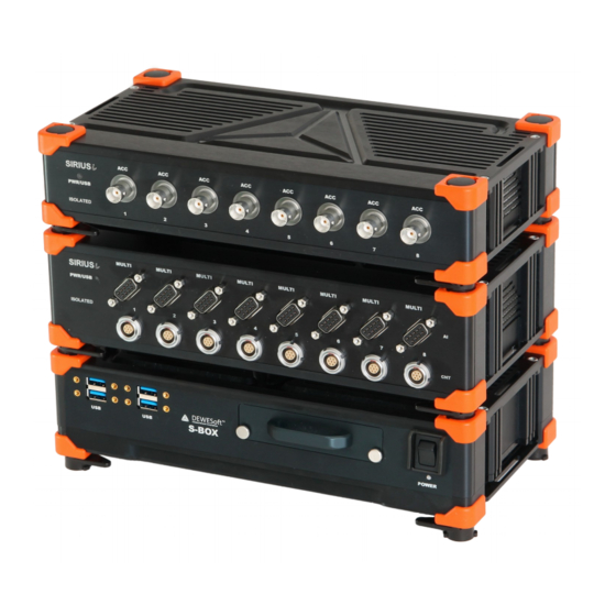
Power plug – you MUST connect USB – see USB on page 27 4.1.2 Multi Slice In a single box you can have 1, 2, 3 or 4 slices, plus an optional S-BOX (see 4.3 SIRIUS-SBOX2 on page 30) at the bottom. -
Page 31: Extended Height Enclosure
(high speed) modules. You can even mix isolated and differential slices. The analogue output option is available only for for the dual core series. For more detailed information about the system please refer to 4.6 SIRIUS-R8 on page 36. measurement innovation... -
Page 32: Connectors At The Rear Side
DEWESoft® 4.2 Connectors at the rear side 4.2.1 Single Slice Version USB The SIRIUS® USB chassis has following connectors at the rear side. Illustration 47: SIRIUS chassis: connectors on the back side 4.2.1.1 CAN (DSUB-9) See also connector CAN in Illustration 47 on page 26. -
Page 33: Single Slice Version Ethercat
4.2.1.6 GND connector See connector GND in Illustration 47 on page 26. For correct measurements, it is highly recommended to ground the SIRIUS® with GND banana plug on the rear side. WARNING It is mandatory to connect a ground cable to the GND connector of the SIRIUS® when you are working with high voltages: e.g. -
Page 34: Multi Slice Version
4.2.2.3 EtherCAT®: GND connector See connector GND in Illustration 52 on page 27. For correct measurements, it is highly recommended to ground the SIRIUS® with GND banana plug on the rear side. WARNING It is mandatory to connect a ground cable to the GND connector of the SIRIUS® when you are working with high voltages: e.g. -
Page 35: Analogue Out Version
Enclosure Overview DEWESoft® DEWESoft® DEWESoft® DEWESoft® DEWESoft® DEWESoft® DEWESoft® DEWESoft® DEWESoft® DEWESoft® DEWESoft® DEWESoft® 4.2.4 Analogue out version The optional analogue output version has the same connectors, as the Single Slice version plus 8 BNC connectors for the analogue output channels (see also: 5.22 Analogue out OPTION on page 125):... -
Page 36: Sirius-Sbox2
The SIRIUS-SBOX2 is an integrated powerful PC in a rugged SIRIUS® chassis: with an Intel® Core™ i7 processor and a fast SSD drive. The SIRIUS-SBOX2 is available in the single slice version and also in the box version (see 4.1 Enclosure types on page 23). -
Page 37: Front Side
DEWESoft® DEWESoft® DEWESoft® DEWESoft® DEWESoft® DEWESoft® 4.3.2 Front side Illustration 57: SIRIUS-SBOX2: Connectors at the front side 4.3.3 Rear side Illustration 58: SIRIUS-SBOX2: Connectors at the rear side 4.3.3.1 Power connector Name L2B3f Power connector (on the S-BOX): ECG.2B.303.CLV Mating connector (for the cable): FGJ.2B.303.CLAD92... -
Page 38: Siriusf-Sbox
4.4 SIRIUS -SBOX The SIRIUSf-BOX is an integrated powerful PC in a rugged SIRIUS® fanless chassis: with an Intel® Core™ processor and a fast SSD drive. The S-BOX is also available in a single slice version. High speed CPU: Intel® Core™... -
Page 39: Specifications F-Sbox
Humidity 95% RH non condensing @ 60°C Shock & Vibration VIBRATION SWEEP SINUS (EN 60068-2-6:2008) VIBRATION RANDOM (EN 60721-3-2: 1997 - Class 2M2) SHOCK (EN 60068-2-27:2009) 4.4.2 Front Side Illustration 62: SIRIUS S-BOX Frontside 4.4.3 Rear Side Illustration 63: SIRIUS S-BOX: Connectors at the rear side... -
Page 40: Sirius-R2D
+12V (max. 0.5A) connect! 4.5 SIRIUS-R2D ir/r The SIRIUS-R2D is a box that can have up to 2 SIRIUS slices (32 channels). A Microsoft® Surface 2 Pro which must be mounted in the closable top cover and provides following features: Technical Specifications Display 10.6“... -
Page 41: Frontside
Enclosure Overview DEWESoft® DEWESoft® DEWESoft® DEWESoft® DEWESoft® DEWESoft® DEWESoft® DEWESoft® DEWESoft® DEWESoft® DEWESoft® DEWESoft® 4.5.1 Frontside 4.5.1.1 USB The internal USB hub is connected via a USB3 connection to the Surface device. 4.5.1.2 Power connector Name L2B2f Power connector (on the S-BOX): ECG.2B.302 Mating connector (for the cable): FGJ.2B.302... -
Page 42: Sirius-R8
Note that there is no distinction between IN and OUT – it does not matter which connector you use. 4.6 SIRIUS-R8 The SIRIUS-R8 is a rugged chassis which provides 8 slots for SIRIUS® measurement modules and has an integrated powerful PC: with an Intel® Core™ i7 processor and a fast SSD drive. -
Page 43: Specifications R8
120 GB, while the measurement data is stored on the exchangeable SSD. Illustration 69: SIRIUS-R8 front-side This allows for a quick exchange of the SSD where your valuable data is stored on. -
Page 44: Front Side
Illustration 72: SIRIUS Sync connector: pin-out (LEMO 4pin) Since there are 2 connectors it's easy to chain several SIRIUS® chassis (or DEWE-43, DS-CAN2, etc.) together. Note that there is no distinction between IN and OUT – it does not matter which connector you use. -
Page 45: Rear Side
Illustration 73: GPS Connector TXD GPS port D GPS port D is reserved. Do not +12V (max. 0.5A) connect! 4.6.3 Rear Side Illustration 74: SIRIUS-R8: Rearside Remote-On may not be available for units before Q1/2013 measurement innovation measurement innovation measurement innovation measurement innovation... -
Page 46: Sirius-R8D
DEWESoft® 4.7 SIRIUS-R8D The SIRIUS-R8D is a rugged chassis which provides 8 slots for SIRIUS® measurement modules and has an integrated powerful PC: with an Intel® Core™ i7 processor and a fast SSD drive. The SIRIUS-R8D has the highest possible data through-put, since each measurement module has a dedicated USB2 line to the CPU (no USB-hub). -
Page 47: Front Side (Display)
DEWESoft® DEWESoft® DEWESoft® DEWESoft® DEWESoft® DEWESoft® DEWESoft® DEWESoft® DEWESoft® 4.7.2 Front Side (Display) Illustration 76: SIRIUS-R8D: Front-side 4.7.3 Rear Side Illustration 77: SIRIUS-R8D: Rearside measurement innovation measurement innovation measurement innovation measurement innovation measurement innovation measurement innovation measurement innovation Doc-Version: 1.4.2 www.dewesoft.com... - Page 48 Illustration 80: SIRIUS Sync connector: pin-out (LEMO 4pin) Since there are 2 connectors it's easy to chain several SIRIUS® chassis (or DEWE-43, DS-CAN2, etc.) together. Note that there is no distinction between IN and OUT – it does not matter which connector you use.
-
Page 49: Dimensions
Enclosure Overview DEWESoft® DEWESoft® DEWESoft® DEWESoft® DEWESoft® DEWESoft® DEWESoft® DEWESoft® DEWESoft® DEWESoft® DEWESoft® DEWESoft® 4.8 Dimensions All versions (Single Slice, Multi Slice, S-BOX) have the same depth: Illustration 81: Dimensions: Single Slice Version 4.8.1 Single Slice Version Illustration 82: Dimensions: Single Slice Version... -
Page 50: Multi Slice Version
DEWESoft® DEWESoft® DEWESoft® DEWESoft® DEWESoft® DEWESoft® DEWESoft® DEWESoft® 4.8.2 Multi Slice Version Illustration 83: Dimensions: MultiSlice Version 4.8.3 Sirius R2D : Dimensions: R2D Illustration 84 measurement innovation measurement innovation measurement innovation measurement innovation measurement innovation measurement innovation measurement innovation Page 44/166 www.dewesoft.com... -
Page 51: Sirius R8D
DEWESoft® DEWESoft® DEWESoft® DEWESoft® DEWESoft® DEWESoft® DEWESoft® DEWESoft® DEWESoft® DEWESoft® DEWESoft® 4.8.4 Sirius R8D : Dimensions: R8D Illustration 85 4.8.4.1 R8D Mounting Front Handle Alu: Vijak M5x10 Vgr.Gl TX RF 19'' Bracket: Vijak M4X8 Vgr.Gl. TX RF measurement innovation measurement innovation... -
Page 52: Sirius R8
SIRIUS® DEWESoft® DEWESoft® DEWESoft® DEWESoft® DEWESoft® DEWESoft® DEWESoft® DEWESoft® DEWESoft® DEWESoft® DEWESoft® DEWESoft® 4.8.5 Sirius R8 Illustration 86: SIRIUS® Rack Dimensions measurement innovation measurement innovation measurement innovation measurement innovation measurement innovation measurement innovation measurement innovation Page 46/166 www.dewesoft.com Doc-Version: 1.4.2... -
Page 53: Sirius® Measurement Modules
PC (or S-BOX). If a USB hub is used, the USB bandwidth is shared by the connected USB devices (i.e. SIRIUS® slices) and thus you may not be able to use the max. possible sampling rate. Note, that also the USB connectors on laptops are often internally connected to a USB hub! Note, that this will for sure not happen when you use the SIRIUS-R8 (see 4.6 SIRIUS-R8 on page 36 ), because the... - Page 54 Weak points of standard EtherCAT®: Master sends the empty message train i.e. when DEWESoft® is the master and does not send the empty message for some reason, there will be no data on the bus Real time performance required from computer...
-
Page 55: Data Transfer Combinations
DEWESoft® DEWESoft® 5.1.3 Data Transfer Combinations DEWESoft® can only acquire data from Dewesoft Hardware which uses the DS-EtherCAT+ protocol. The SIRIUS EtherCAT® slices have 2 modes of operation: Buffered mode: for DEWESoft® software Standard EtherCAT® mode: for standard EtherCAT® masters 5.2 Technology overview... -
Page 56: Isolated Version: Usb
SIRIUS® DEWESoft® DEWESoft® DEWESoft® DEWESoft® DEWESoft® DEWESoft® DEWESoft® DEWESoft® DEWESoft® DEWESoft® DEWESoft® DEWESoft® 5.2.4 Isolated version: USB The (standard) SIRIUSi modules are isolated between themselves and the main board. Some modules generate power for electronics and for external pins: this power supply is again... -
Page 57: Sirius® Differential Version: Usb
DEWESoft® DEWESoft® DEWESoft® DEWESoft® 5.2.5 SIRIUS® differential version: USB The basic concept is the same like on the isolated version but without galvanic isolation for the module power supply and the data interface. Illustration 91: Differential Motherboard 5.2.6 Isolated version: EtherCAT®... -
Page 58: Sirius® Slice Configuration
DEWESoft® DEWESoft® DEWESoft® DEWESoft® DEWESoft® DEWESoft® DEWESoft® DEWESoft® DEWESoft® DEWESoft® 5.3 SIRIUS® Slice Configuration Standard Slice SIRIUSi 8xACC SIRIUSi 6xACC, 2xACC+ 8 x ACC channels (see page 57) 6 x ACC, 2 x ACC+ channels (see page 57) SIRIUSi 8xMULTI... -
Page 60: Sirius® Dual Core Specifications
SIRIUS® DEWESoft® DEWESoft® DEWESoft® DEWESoft® DEWESoft® DEWESoft® DEWESoft® DEWESoft® DEWESoft® DEWESoft® DEWESoft® DEWESoft® 5.4 SIRIUS® Dual Core specifications High Dynamic: Dual Core with 2x24Bit Analogue modules MULTI STGM STGM+ With counter and DIO ACC+ CHG+ STG+ STGM-DB Isolated version ■... -
Page 61: Sirius® Hd And Hs Specifications
13 Fanless operation only for BNC or Banana version (without excitation) 14 Pinout of analogue input connector may limit functionality. MSI-Option requires DB9 connector. 15 200kHz for Charge 16 Applies only to isolated SIRIUS version 17 One complete slice with same modules measurement innovation... -
Page 62: General Specifications
Synchronisation Delay between slices 50 nsec USB: Max. Sync-cable length 100 m (Master/Slave), 200 m (Irig) EtherCAT®: Max. cable length Table 8: SIRIUS® Modules: General Specifications 50°C with airflow of 3m/sec measurement innovation measurement innovation measurement innovation measurement innovation measurement innovation... -
Page 63: Acc / Acc
5.7.1 ACC: Specifications Voltage, IEPE, current (ext. Shunt), Inputs ACC+ only: counter, discrete 24bit delta-sigma dual core with anti-aliasing filter (5.2.1 SIRIUS® Dual Core series: High Dynamic ADC Type (up to 160 dB) page 49) Sampling Rate Simultaneous 200kS/sec Ranges (Dual Core Low Range) ±10V (±500mV) -
Page 64: Acc: Voltage
DEWESoft® DEWESoft® DEWESoft® DEWESoft® DEWESoft® Illustration 95: CNT: counter pin-out (LEMO 7pin) Illustration 96: SIRIUS 6xACC, 2xACC+ Connector type L1B7f Connector on the module: EGG.1B.307.CLL Mating cable connector: FGG.1B.307.CLAD52 Table 10: ACC+ counter connector type Digital Output Configuration The “switch” of the open collector output is closed when active. -
Page 65: Chg / Chg
Input Protection ±25Volt continuous Alarm output Open collector, max. 100mA/30Volt Sensor supply 5V/100mA;12V/50mA Additional Specifications Input connector BNC or TNC (others on request) TEDS support IEPE mode only Table 11: SIRIUS-CHG specifications measurement innovation measurement innovation measurement innovation measurement innovation measurement innovation... -
Page 66: Chg Bnc
DEWESoft® DEWESoft® DEWESoft® DEWESoft® DEWESoft® DEWESoft® DEWESoft® DEWESoft® DEWESoft® 5.8.2 CHG BNC Illustration 99: SIRIUS-CHG: pin-out Illustration 100: SIRIUS 8xCHG (BNC) 5.8.3 CHG+ (Counter) L1B7f Illustration 101: CNT: counter pin-out (LEMO 7pin) Illustration 102: SIRIUS 6xCHG, 2xCHG+ Connector type L1B7f Connector on the module: EGG.1B.307.CLL... -
Page 67: Chg: Voltage
SIRIUS® Measurement Modules DEWESoft® DEWESoft® DEWESoft® DEWESoft® DEWESoft® DEWESoft® DEWESoft® DEWESoft® DEWESoft® DEWESoft® DEWESoft® DEWESoft® 5.8.4 CHG: Voltage Illustration 103: CHG Voltage 5.8.5 CHG: IEPE Illustration 104: CHG IEPE 5.8.6 CHG: Charge Illustration 105: CHG Charge measurement innovation measurement innovation... -
Page 68: Hvv2 Specifications
Illustration 107: SIRIUS 8xHV-BAN Banana plug WARNING It is mandatory to connect a ground cable to the GND connector of the SIRIUS® when you are working with high voltages (see also 4.2.1.6 GND connector on page 27) measurement innovation measurement innovation... - Page 69 SIRIUS® Measurement Modules DEWESoft® DEWESoft® DEWESoft® DEWESoft® DEWESoft® DEWESoft® DEWESoft® DEWESoft® DEWESoft® DEWESoft® DEWESoft® DEWESoft® 5.9.2.1 HV: Voltage Illustration 108: SIRIUS-HV: Voltage measurement innovation measurement innovation measurement innovation measurement innovation measurement innovation measurement innovation measurement innovation Doc-Version: 1.4.2 www.dewesoft.com Page 63/166...
-
Page 70: Lv / Lv
5.10.1 LVv2 Specifications Inputs Voltage, full bridge strain, current (ext. Shunt) 24bit delta-sigma dual core with 100/5 kHz analogue anti-aliasing filter (5.2.1 SIRIUS® Dual Core ADC Type series: High Dynamic (up to 160 dB) page 49) Sampling Rate Simultaneous 200kS/sec Dual Core Ranges (Low Range) ±200V (10 V) -
Page 71: Lv+ (Counter) L1B7F
Mating cable connector: FGG.1B.307.CLAD52 Table 15: LV+ counter connector type Digital Output Configuration The “switch” of the open collector output is closed when active. 5.10.3 LV BAN Illustration 111: SIRIUS-LV pin-out Banana plug Illustration 112: SIRIUS 8xLV-BAN measurement innovation measurement innovation... -
Page 72: Lv Bnc
Illustration 115: SIRIUS-LV pin-out DSUB-9 Illustration 116: SIRIUS 8xLV Digital Status Input Pin 5 DI (Status) can be used for digital status input: i.e. show alarm status in DEWESoft® when a current clamp is open. measurement innovation measurement innovation measurement innovation... - Page 73 SIRIUS® Measurement Modules DEWESoft® DEWESoft® DEWESoft® DEWESoft® DEWESoft® DEWESoft® DEWESoft® DEWESoft® DEWESoft® DEWESoft® DEWESoft® DEWESoft® 5.10.5.1 LV DSUB-9: Voltage Voltage – Differential Use only when the sensor is powered by the Voltage - Single Ended excitation voltage of the module.
- Page 74 SIRIUS® DEWESoft® DEWESoft® DEWESoft® DEWESoft® DEWESoft® DEWESoft® DEWESoft® DEWESoft® DEWESoft® DEWESoft® DEWESoft® DEWESoft® 5.10.5.3 LV DSUB-9: Bridge Full Bridge measurement innovation measurement innovation measurement innovation measurement innovation measurement innovation measurement innovation measurement innovation Page 68/166 www.dewesoft.com Doc-Version: 1.4.2...
-
Page 75: Multi
5.11.1 MULTI: Specifications Inputs Voltage, full, ½, ¼ bridge (120Ω and 350Ω), current (ext. Shunt), counter, digital 24bit delta-sigma dual core with 100/5 kHz analogue anti-aliasing filter (5.2.1 SIRIUS® Dual Core ADC Type series: High Dynamic (up to 160 dB) page 49) -
Page 76: Multi Dsub-15
8 Sns- Sense - 9 GND Ground Input - 11 +5V +5V supply 12 +12V +12V supply Illustration 118: SIRIUS-MULTI pin-out DSUB-15 13 IN0/A Counter input IN0/A 14 IN1/B Counter input IN1/B 15 IN2/Z Counter input IN2/Z HINT You can use the analogue input, analogue output and counters at the same time. - Page 77 SIRIUS® Measurement Modules DEWESoft® DEWESoft® DEWESoft® DEWESoft® DEWESoft® DEWESoft® DEWESoft® DEWESoft® DEWESoft® DEWESoft® DEWESoft® DEWESoft® 5.11.2.1 MULTI DSUB-15: Voltage Voltage – Differential Use only when the sensor is powered by the Voltage - Single Ended excitation voltage of the module.
- Page 78 SIRIUS® DEWESoft® DEWESoft® DEWESoft® DEWESoft® DEWESoft® DEWESoft® DEWESoft® DEWESoft® DEWESoft® DEWESoft® DEWESoft® DEWESoft® 5.11.2.4 MULTI DSUB-15: Bridge Full Bridge Half Bridge Quarter Bridge – 3 wire measurement innovation measurement innovation measurement innovation measurement innovation measurement innovation measurement innovation measurement innovation Page 72/166 www.dewesoft.com...
-
Page 79: Multi-L2B16F
9 GND Ground Input - 11 +5V +5V (max. 100mA) supply 12 +14V5 +14.5V (max. 50mA) supply Illustration 119: SIRIUS-MULTI-L2B16F pin-out 13 IN0/A Counter input IN0/A 14 IN1/B Counter input IN1/B 15 IN2/Z Counter input IN2/Z 16 -14V5 -14.5V (max. 50mA) supply HINT You can use the analogue input, analogue output and counters at the same time. - Page 80 SIRIUS® DEWESoft® DEWESoft® DEWESoft® DEWESoft® DEWESoft® DEWESoft® DEWESoft® DEWESoft® DEWESoft® DEWESoft® DEWESoft® DEWESoft® 5.11.3.2 MULTI-L2B16f: Current External Direct Shunt External Loop Powered Shunt 5.11.3.3 MULTI-L2B16f: Potentiometer measurement innovation measurement innovation measurement innovation measurement innovation measurement innovation measurement innovation measurement innovation Page 74/166 www.dewesoft.com...
- Page 81 SIRIUS® Measurement Modules DEWESoft® DEWESoft® DEWESoft® DEWESoft® DEWESoft® DEWESoft® DEWESoft® DEWESoft® DEWESoft® DEWESoft® DEWESoft® DEWESoft® 5.11.3.4 MULTI-L2B16f: Bridge Full Bridge Half Bridge Quarter Bridge – 3 wire measurement innovation measurement innovation measurement innovation measurement innovation measurement innovation measurement innovation measurement innovation Doc-Version: 1.4.2...
-
Page 82: Stgm / Stgm
Inputs Voltage, full bridge strain, ½ bridge strain, ¼ bridge strain (120Ω and 350Ω), current (ext. Shunt) 24bit delta-sigma dual core with 100/5 kHz analogue anti-aliasing filter (5.2.1 SIRIUS® Dual Core ADC Type series: High Dynamic (up to 160 dB) page 49) -
Page 83: Stgm+ (Counter) L1B7F
The STGM-DB is the same as the STG-M but has an additional DSUB-37 male connector for 8 counter or 24 digital inputs and an additional DSUB-25 female connector for 8 digital outputs. Thus the enclosure is higher than the standard enclosure (see 4.1.3 Extended Height Enclosure on page 25). Illustration 122: SIRIUS-STGM-DB (2 slices) measurement innovation measurement innovation... - Page 84 SIRIUS® DEWESoft® DEWESoft® DEWESoft® DEWESoft® DEWESoft® DEWESoft® DEWESoft® DEWESoft® DEWESoft® DEWESoft® DEWESoft® DEWESoft® Illustration 123: DSUB 37 pins Illustration 124: DSUB 25 pins this voltage is guaranteed to be <= 12V When the supply voltage is <12V, then this voltage will be 2V lower than the supply voltage: e.g.
-
Page 85: Stgm Dsub-9
Sense + Input - Exc- Excitation - TEDS TEDS Illustration 126: SIRIUS-STGM pin-out DSUB-9 5.12.4.1 STGM DSUB-9: Voltage Voltage – Differential Use only when the sensor is powered by the Voltage - Single Ended excitation voltage of the module. measurement innovation... - Page 86 SIRIUS® DEWESoft® DEWESoft® DEWESoft® DEWESoft® DEWESoft® DEWESoft® DEWESoft® DEWESoft® DEWESoft® DEWESoft® DEWESoft® DEWESoft® 5.12.4.2 STGM DSUB-9: Current External Direct Shunt External Loop Powered Shunt 5.12.4.3 STGM DSUB-9: Potentiometer measurement innovation measurement innovation measurement innovation measurement innovation measurement innovation measurement innovation...
-
Page 87: Stgm-L2B8F
Description Exc+ Excitation + Input - Input + Exc- Excitation - Shield Teds Teds Ground Illustration 127: SIRIUS-STG-M: pin-out Lemo 8-pin Reserved measurement innovation measurement innovation measurement innovation measurement innovation measurement innovation measurement innovation measurement innovation Doc-Version: 1.4.2 www.dewesoft.com Page 81/166... - Page 88 SIRIUS® DEWESoft® DEWESoft® DEWESoft® DEWESoft® DEWESoft® DEWESoft® DEWESoft® DEWESoft® DEWESoft® DEWESoft® DEWESoft® DEWESoft® 5.12.5.1 STGM-L2B8f: Voltage Voltage – Differential Use only when the sensor is powered by the Voltage - Single Ended excitation voltage of the module. 5.12.5.2 STGM-L2B8f: Current...
- Page 89 SIRIUS® Measurement Modules DEWESoft® DEWESoft® DEWESoft® DEWESoft® DEWESoft® DEWESoft® DEWESoft® DEWESoft® DEWESoft® DEWESoft® DEWESoft® DEWESoft® 5.12.5.4 STGM-L2B8f: Bridge Full Bridge Half Bridge Quarter Bridge – 3 wire measurement innovation measurement innovation measurement innovation measurement innovation measurement innovation measurement innovation measurement innovation Doc-Version: 1.4.2...
-
Page 90: Stgm-L2B16F
9 GND Ground Input - 11 +5V +5V (max. 100mA) supply 12 +14V5 +14.5V (max. 50mA) supply Illustration 128: SIRIUS-STGM-L2B16f pin-out 13 IN0/A Counter input IN0/A 14 IN1/B Counter input IN1/B 15 IN2/Z Counter input IN2/Z 16 -14V5 -14.5V (max. 50mA) supply HINT You can use the analogue input and counters at the same time. - Page 91 SIRIUS® Measurement Modules DEWESoft® DEWESoft® DEWESoft® DEWESoft® DEWESoft® DEWESoft® DEWESoft® DEWESoft® DEWESoft® DEWESoft® DEWESoft® DEWESoft® 5.12.6.2 STGM-L2B16f: Current External Direct Shunt External Loop Powered Shunt 5.12.6.3 STGM-L2B16f: Potentiometer measurement innovation measurement innovation measurement innovation measurement innovation measurement innovation measurement innovation measurement innovation Doc-Version: 1.4.2...
- Page 92 SIRIUS® DEWESoft® DEWESoft® DEWESoft® DEWESoft® DEWESoft® DEWESoft® DEWESoft® DEWESoft® DEWESoft® DEWESoft® DEWESoft® DEWESoft® 5.12.6.4 STGM-L2B16f: Bridge Full Bridge Half Bridge Quarter Bridge – 3 wire measurement innovation measurement innovation measurement innovation measurement innovation measurement innovation measurement innovation measurement innovation Page 86/166 www.dewesoft.com...
-
Page 93: Stg / Stg
Inputs Voltage, full bridge strain, ½ bridge strain, ¼ bridge strain, potentiometer, RTD, Resistance ADC Type 24bit delta-sigma dual core with 100/5 kHz analogue anti-aliasing filter (5.2.1 SIRIUS® Dual Core series: High Dynamic (up to 160 dB) page 49) Sampling Rate Simultaneous 200kS/sec Dual Core Ranges (Low) ±50V (2.5 V) -
Page 94: Stg+ (Counter) L1B7F
Misc. function Excitation level monitoring, self check function Input Connector DSUB - 9, LEMO2B 7pin LEMO2B 10pin (others on request) TEDS support Standard + MSI adapters Table 21: SIRIUS-STG specifications II 5.13.2 STG+ (Counter) L1B7f Illustration 129: CNT: counter pin-out... - Page 95 Input + Exc- Excitation - Sns- Sense - Input - Illustration 132: SIRIUS-STG: pin-out Lemo 7-pin ¼ Bridge/Shunt 5.13.3.1 STG-L2B7f: Voltage Voltage – Differential Use only when the sensor is powered by the Voltage - Single Ended excitation voltage of the module.
- Page 96 SIRIUS® DEWESoft® DEWESoft® DEWESoft® DEWESoft® DEWESoft® DEWESoft® DEWESoft® DEWESoft® DEWESoft® DEWESoft® DEWESoft® DEWESoft® 5.13.3.3 STG-L2B7f: Temperature 5.13.3.4 STG-L2B7f: Resistance 5.13.3.5 STG-L2B7f: Potentiometer measurement innovation measurement innovation measurement innovation measurement innovation measurement innovation measurement innovation measurement innovation Page 90/166 www.dewesoft.com Doc-Version: 1.4.2...
-
Page 97: Stg-L2B10F
Input + Input - Sns+ Sense + Sns- Sense - Di-Cnt Digital I/O, Counter TEDS TEDs Illustration 134: SIRIUS-STG: pin-out Lemo 10-pin R+/SHUNT Resistance/SHUNT GND-iso measurement innovation measurement innovation measurement innovation measurement innovation measurement innovation measurement innovation measurement innovation Doc-Version: 1.4.2 www.dewesoft.com... - Page 98 SIRIUS® DEWESoft® DEWESoft® DEWESoft® DEWESoft® DEWESoft® DEWESoft® DEWESoft® DEWESoft® DEWESoft® DEWESoft® DEWESoft® DEWESoft® 5.13.4.1 STG-L2B10f: Voltage Voltage – Differential Use only when the sensor is powered by the Voltage - Single Ended excitation voltage of the module. 5.13.4.2 STG-L2B10f: Current...
- Page 99 SIRIUS® Measurement Modules DEWESoft® DEWESoft® DEWESoft® DEWESoft® DEWESoft® DEWESoft® DEWESoft® DEWESoft® DEWESoft® DEWESoft® DEWESoft® DEWESoft® 5.13.4.4 STG-L2B10f: Resistance 5.13.4.5 STG-L2B10f: Potentiometer measurement innovation measurement innovation measurement innovation measurement innovation measurement innovation measurement innovation measurement innovation Doc-Version: 1.4.2 www.dewesoft.com Page 93/166...
-
Page 100: Stg Dsub-9
Full Bridge Half Bridge Quarter Bridge – 3 wire Quarter Bridge – 4 wire 5.13.5 STG DSUB-9 Illustration 135: SIRIUS-STG pin-out DSUB-9 Illustration 136: SIRIUS STG8 DSUB9 measurement innovation measurement innovation measurement innovation measurement innovation measurement innovation measurement innovation measurement innovation Page 94/166 www.dewesoft.com... - Page 101 SIRIUS® Measurement Modules DEWESoft® DEWESoft® DEWESoft® DEWESoft® DEWESoft® DEWESoft® DEWESoft® DEWESoft® DEWESoft® DEWESoft® DEWESoft® DEWESoft® 5.13.5.1 STG DSUB-9: Voltage Voltage – Differential Use only when the sensor is powered by the Voltage - Single Ended excitation voltage of the module.
- Page 102 SIRIUS® DEWESoft® DEWESoft® DEWESoft® DEWESoft® DEWESoft® DEWESoft® DEWESoft® DEWESoft® DEWESoft® DEWESoft® DEWESoft® DEWESoft® 5.13.5.4 STG DSUB-9: Resistance 5.13.5.5 STG DSUB-9: Potentiometer measurement innovation measurement innovation measurement innovation measurement innovation measurement innovation measurement innovation measurement innovation Page 96/166 www.dewesoft.com Doc-Version: 1.4.2...
- Page 103 SIRIUS® Measurement Modules DEWESoft® DEWESoft® DEWESoft® DEWESoft® DEWESoft® DEWESoft® DEWESoft® DEWESoft® DEWESoft® DEWESoft® DEWESoft® DEWESoft® 5.13.5.6 STG DSUB-9: Bridge Full Bridge Half Bridge Quarter Bridge – 3 wire Quarter Bridge – 4 wire measurement innovation measurement innovation measurement innovation measurement innovation...
-
Page 104: Hd-Acc
5.14 HD-ACC 5.14.1 HD-ACC Specifications Inputs Voltage, IEPE, current (ext. Shunt) 24bit delta-sigma with 100 kHz/5 kHz anti-aliasing filter (5.2.1 SIRIUS® Dual Core series: ADC Type High Dynamic (up to 160 dB) page 49) Sampling Rate Simultaneous 200kS/sec Ranges ±10 V ±5 V... -
Page 105: Hd-Acc: Voltage
SIRIUS® Measurement Modules DEWESoft® DEWESoft® DEWESoft® DEWESoft® DEWESoft® DEWESoft® DEWESoft® DEWESoft® DEWESoft® DEWESoft® DEWESoft® DEWESoft® 5.14.3 HD-ACC: Voltage Illustration 139: HD-ACC Voltage 5.14.4 HD-ACC: IEPE Illustration 140: HD-ACC IEPE measurement innovation measurement innovation measurement innovation measurement innovation measurement innovation measurement innovation measurement innovation Doc-Version: 1.4.2... -
Page 106: Hd-Lv
DEWESoft® DEWESoft® 5.15 HD-LV 5.15.1 HD-LV: Specifications Inputs Voltage, full bridge strain, current (ext. Shunt) 24bit delta-sigma with 100kHz/5kHz anti-aliasing filter (5.2.2 SIRIUS®-HD-series: High ADC Type density (16 channel per slice) page 49) Sampling Rate Simultaneous 200kS/sec Ranges ±100V ±10V ±1... - Page 107 SIRIUS® Measurement Modules DEWESoft® DEWESoft® DEWESoft® DEWESoft® DEWESoft® DEWESoft® DEWESoft® DEWESoft® DEWESoft® DEWESoft® DEWESoft® DEWESoft® Pin Name Description Exc+ Excitation + Input + Sns- Sense - Ground n.c. Not connected Sns+ Sense + Input - Exc- Excitation - TEDS TEDS Illustration 142: 5.12.2 HD-LV pin-out DSUB-9...
-
Page 108: Hd-Lv Bnc
DEWESoft® DEWESoft® DEWESoft® DEWESoft® DEWESoft® DEWESoft® 5.15.2.3 HD-LV: Bridge Full Bridge 5.15.3 HD-LV BNC Illustration 143: SIRIUS HD-LV BNC 5.15.4 HD-LV BNC: Voltage Illustration 144: HD-LV BNC Voltage measurement innovation measurement innovation measurement innovation measurement innovation measurement innovation measurement innovation... -
Page 109: Hd-Stgs
5.16.1 HD-STGS: Specifications Inputs Voltage, full bridge strain, half bridge strain, quarter bridge strain (120Ω and 350Ω), current (ext. Shunt) 24bit delta-sigma with 100kHz/5kHz anti-aliasing filter (5.2.2 SIRIUS®-HD-series: High density (16 ADC Type channel per slice) page 49) Sampling Rate Simultaneous 200kS/sec Dual Core Ranges (Low Range) ±10V... -
Page 110: Hd-Stgs
Sns+ Sense + Input - Exc- Excitation - TEDS TEDS Illustration 146: SIRIUS-HD-STGS pin-out 5.16.2.1 HD-STGS: Voltage Voltage – Differential Use only when the sensor is powered by the Voltage - Single Ended excitation voltage of the module. measurement innovation... - Page 111 SIRIUS® Measurement Modules DEWESoft® DEWESoft® DEWESoft® DEWESoft® DEWESoft® DEWESoft® DEWESoft® DEWESoft® DEWESoft® DEWESoft® DEWESoft® DEWESoft® 5.16.2.2 HD-STGS: Current External Direct Shunt External Loop Powered Shunt 5.16.2.3 HD-STGS: Potentiometer measurement innovation measurement innovation measurement innovation measurement innovation measurement innovation measurement innovation measurement innovation Doc-Version: 1.4.2...
-
Page 112: Hd-Stgs-L1B10F
SIRIUS® DEWESoft® DEWESoft® DEWESoft® DEWESoft® DEWESoft® DEWESoft® DEWESoft® DEWESoft® DEWESoft® DEWESoft® DEWESoft® DEWESoft® 5.16.2.4 HD-STGS: Bridge Full Bridge Half Bridge Quarter Bridge – 3 wire 5.16.3 HD-STGS-L1B10f Illustration 147: HD-STGS-L1B10f measurement innovation measurement innovation measurement innovation measurement innovation measurement innovation... - Page 113 Sense + ¼ Bridge/Shunt Input + Exc+ Excitation + Measurement GND Exc- Excitation - Sns- Sense - Illustration 148: SIRIUS-HD-STGS: pin-out Lemo 10-pin Shield connection to chassis TEDS TEDS measurement innovation measurement innovation measurement innovation measurement innovation measurement innovation measurement innovation measurement innovation Doc-Version: 1.4.2...
-
Page 114: Hs-Acc / Hs-Acc
Inputs ACC+ only: counter, discrete 16bit SAR with 100kHz 5 order analogue AAF filter or bypass ADC Type (5.2.3 SIRIUS®-HS series: High speed and bandwidth page 49) Analogue bandwidth 500 kHz Sampling Rate Simultaneous 1 MS/sec Voltage ranges ±10 Volt ±5 Volt... -
Page 115: Hs-Acc+ (Counter) L1B7F
SIRIUS® Measurement Modules DEWESoft® DEWESoft® DEWESoft® DEWESoft® DEWESoft® DEWESoft® DEWESoft® DEWESoft® DEWESoft® DEWESoft® DEWESoft® DEWESoft® 5.17.3 HS-ACC+ (Counter) L1B7f The HS-ACC+ modules are perfect for high speed sound and vibration IEPE channels plus counter applications. In addition to the HS-ACC module, it also has a 7-pin Lemo connector for digital counters. -
Page 116: Hs-Acc: Iepe
SIRIUS® DEWESoft® DEWESoft® DEWESoft® DEWESoft® DEWESoft® DEWESoft® DEWESoft® DEWESoft® DEWESoft® DEWESoft® DEWESoft® DEWESoft® 5.17.5 HS-ACC: IEPE Illustration 154: HS-ACC IEPE measurement innovation measurement innovation measurement innovation measurement innovation measurement innovation measurement innovation measurement innovation Page 110/166 www.dewesoft.com Doc-Version: 1.4.2... -
Page 117: Hs-Chg / Hs-Chg
Voltage, IEPE, Charge, Current (ext. Shunt) 16bit SAR with 100kHz 5 order analogue AAF filter or 500KHz bandwidth ADC Type (5.2.3 SIRIUS®-HS series: High speed and bandwidth page 49) Analogue bandwidth 500 kHz (200 kHz for Charge) Sampling Rate Simultaneous 1 MS/sec Voltage ranges 7 ranges: ±10, ±5, ±2, ±1, ±0.5, ±0.2, ±0.1 Volt... -
Page 118: Hs-Chg Bnc
DEWESoft® DEWESoft® DEWESoft® DEWESoft® DEWESoft® DEWESoft® DEWESoft® DEWESoft® DEWESoft® 5.18.2 HS-CHG BNC Illustration 155: SIRIUS-ACC: pin-out (BNC) Illustration 156: SIRIUS 8xHS-CHG-BNC 5.18.3 HS-CHG+ (Counter) L1B7f Illustration 157: CNT: counter pin-out (LEMO 7pin) Illustration 158: SIRIUS 6xHS-CHG, 2xHS-CHG+ Connector type L1B7f Connector on the module: EGG.1B.307.CLL... -
Page 119: Hs-Chg: Voltage
SIRIUS® Measurement Modules DEWESoft® DEWESoft® DEWESoft® DEWESoft® DEWESoft® DEWESoft® DEWESoft® DEWESoft® DEWESoft® DEWESoft® DEWESoft® DEWESoft® 5.18.4 HS-CHG: Voltage Illustration 159: HS-CHG Voltage 5.18.5 HS-CHG: IEPE Illustration 160: HS-CHG IEPE 5.18.6 HS-CHG: Charge Illustration 161: HS-CHG IEPE measurement innovation measurement innovation... -
Page 120: Hs-Hv
HS-HV 5.19.1 HS-HV: Specifications Inputs Voltage 16bit SAR with 100kHz 5 order analogue AAF filter or bypass (5.2.1 SIRIUS® Dual Core series: High ADC Type Dynamic (up to 160 dB) page 49) Sampling Rate Simultaneous 1MS/sec Analogue bandwidth 2 MHz Voltage ranges ±1600 V, ±800 V, ±400 V, ±200 V, ±100 V, ±50 V, ±20 V... -
Page 121: Hs-Hv Banana
DEWESoft® DEWESoft® DEWESoft® DEWESoft® DEWESoft® DEWESoft® DEWESoft® DEWESoft® DEWESoft® 5.19.2 HS-HV Banana Illustration 162: SIRIUS-HS-HV pin-out Illustration 163: SIRIUS 8xHS-HV-BAN Banana plug 5.19.2.1 HS-HV: Voltage Illustration 164: HS-HV Voltage measurement innovation measurement innovation measurement innovation measurement innovation measurement innovation measurement innovation measurement innovation Doc-Version: 1.4.2... -
Page 122: Hs-Lv / Hs-Lv
5.20.1 HS-LV Specifications Inputs Voltage, current (ext. Shunt) 16bit SAR with 100kHz 5 order analogue AAF filter or bypass (5.2.1 SIRIUS® Dual Core series: High ADC Type Dynamic (up to 160 dB) page 49) Sampling Rate Simultaneous 1MS/sec Analogue bandwidth... -
Page 123: Hs-Lv+ (Counter) L1B7F
Mating cable connector: FGG.1B.307.CLAD52 Table 32: HS-LV+ counter connector type Digital Output Configuration The “switch” of the open collector output is closed when active. 5.20.3 HS-LV BAN Illustration 167: SIRIUS-HS-LV pin-out Illustration 168: SIRIUS 8xHS-LV-BAN Banana plug measurement innovation measurement innovation... -
Page 124: Hs-Lv Bnc
Illustration 172: SIRIUS 8xHS-LV DSUB9 DSUB-9 Digital Status Input Pin 5 DI (Status) can be used for digital status input: i.e. show alarm status in DEWESoft® when a current clamp is open. 5.20.5.1 HS-LV DSUB-9: Voltage Voltage – Differential Use only when the sensor is powered by the Voltage - Single Ended excitation voltage of the module. - Page 125 SIRIUS® Measurement Modules DEWESoft® DEWESoft® DEWESoft® DEWESoft® DEWESoft® DEWESoft® DEWESoft® DEWESoft® DEWESoft® DEWESoft® DEWESoft® DEWESoft® 5.20.5.2 HS-LV DSUB-9: Current External Direct Shunt External Loop Powered Shunt measurement innovation measurement innovation measurement innovation measurement innovation measurement innovation measurement innovation measurement innovation Doc-Version: 1.4.2...
-
Page 126: Hs-Stg / Hs-Stg
Voltage, full bridge strain, half bridge strain, quarter bridge strain (120Ω and 350Ω), current Inputs (ext. Shunt), resistance, temperature 16bit SAR with 100kHz 5 order analogue AAF filter or bypass (5.2.1 SIRIUS® Dual Core series: High ADC Type Dynamic (up to 160 dB) page 49) Sampling Rate Simultaneous 1MS/sec... -
Page 127: Hs-Stg+ (Counter) L1B7F
Input connector DSUB 9 (others on request) TEDS support Standard + MSI adapters Table 33: SIRIUS-HS-STG specifications 5.21.2 HS-STG+ (Counter) L1B7f As an additional function to the ACC module, the ACC+ module also has a 7-pin Lemo connector for digital counters. -
Page 128: Hs-Stg Dsub-9
DEWESoft® DEWESoft® DEWESoft® 5.21.3 HS-STG DSUB-9 Illustration 176: SIRIUS HS-STG DSUB9 Illustration 175: SIRIUS-HS-STG pin-out DSUB-9 5.21.3.1 HS-STG DSUB-9: Voltage Voltage – Differential Use only when the sensor is powered by the Voltage - Single Ended excitation voltage of the module. - Page 129 SIRIUS® Measurement Modules DEWESoft® DEWESoft® DEWESoft® DEWESoft® DEWESoft® DEWESoft® DEWESoft® DEWESoft® DEWESoft® DEWESoft® DEWESoft® DEWESoft® 5.21.3.2 HS-STG DSUB-9: Current External Direct Shunt External Loop Powered Shunt 5.21.3.3 HS-STG DSUB-9: Temperature 5.21.3.4 HS-STG DSUB-9: Resistance measurement innovation measurement innovation measurement innovation...
- Page 130 SIRIUS® DEWESoft® DEWESoft® DEWESoft® DEWESoft® DEWESoft® DEWESoft® DEWESoft® DEWESoft® DEWESoft® DEWESoft® DEWESoft® DEWESoft® 5.21.3.5 HS-STG DSUB-9: Potentiometer 5.21.3.6 HS-STG DSUB-9: Bridge Full Bridge Half Bridge Quarter Bridge – 3 wire Quarter Bridge – 4 wire measurement innovation measurement innovation measurement innovation...
-
Page 131: Analogue Out Option
5.22 Analogue out OPTION The 8 optional analogue output channels (BNC connectors) at the rear side are available for all SIRIUS® Dual Core slices (see 5.4 SIRIUS® Dual Core specifications on page 54). Note: the Multi modules (see 5.11 MULTI on page 69) have the analogue out channels per default on the front-side connectors. -
Page 133: Measurement
The frequency response of a filter can be classified into a number of different bandforms describing which frequency bands the filter passes (the passband) and which it rejects (the stopband). To discuss the Sirius® filtering, we only need to consider 2 types frequency response:... - Page 134 In Illustration 179 below you can see 3 analogue filters (2 and 8 order) and the Sirius® filter (which is a combination of analogue filter, oversampling and digital filter). Note, that filters with higher order have a sharper damping around the filter frequency:...
- Page 135 DEWESoft® DEWESoft® HINT To get a better understanding of the aliasing effect, we recommend to take the DEWESoft® PRO training course: Spectral analysis using the FFT: http://www.dewesoft.com/pro/course/spectral-analysis-using-the-fft-29 Our professional online training courses are available free of charge to registered users of our homepage.
-
Page 136: Filter Design
Moreover we want to have a linear phase, so we choose a FIR filter (the performance of the DSP in Sirius® is powerful enough to handle this demanding computation). Another important goal is to minimise errors introduced by aliasing. So the FIR filter alone will not be sufficient (since digital filters are subject to aliasing). - Page 137 Measurement DEWESoft® DEWESoft® DEWESoft® DEWESoft® DEWESoft® DEWESoft® DEWESoft® DEWESoft® DEWESoft® DEWESoft® DEWESoft® DEWESoft® 6.1.2.1 Sampling and Digital Filter Our first try is quite naïve: we sample the signal at 2kHz (over twice the frequency that we are interested in) and then apply a digital filter.
-
Page 138: Sirius® Dualcore & Hd: Anti-Aliasing
(i.e. the effect of the aliasing is negligible). Illustration 185 below shows an overview of the components in the Sirius® DualCore and HD modules: after the amplifier there is an Analogue Filter followed by the ADC which uses oversampling and includes a Digital ADC Filter, so that we can get excellent aliasing-free measurement results: : Filtering components in Sirius®... - Page 139 : Filter comparison: Sirius® DualCore vs. analogue filters Illustration 186 In Illustration 186 above, you can see that the Sirius® filter (orange line) is close to perfection and outperforms any of the pure analogue filters (see 6.1.2 Filter Design on page 130 for details) 6.1.3.1 Analogue Filter...
- Page 140 SIRIUS® DEWESoft® DEWESoft® DEWESoft® DEWESoft® DEWESoft® DEWESoft® DEWESoft® DEWESoft® DEWESoft® DEWESoft® DEWESoft® DEWESoft® 6.1.3.3 Digital ADC Filter The filter characteristics of the digital ADC filter will also change automatically depending on the sample-rate: Sample rate 0.1kS/s to 51.2kS/s Frequency (normalised to Fs) Frequency (normalised to Fs) Sample rate 51.2kS/s to 102.4kS/s...
-
Page 141: Dewesoft®: Custom Low Pass Filter Settings
The filtering described in the previous chapters is done in the Sirius® measurement hardware: it assures that the data that Sirius® passes to the DEWESoft® software is aliasing free. But you must be careful not to introduce aliasing again in software. - Page 142 In the example above you can see that the dynamic acquisition rate () is set to 100kHz. The sample rate of the first analogue input channel (AI 1) is set to only 10kHz (). This means, that the Sirius® hardware will send the measurement data of all channels at a rate of 100kHz via USB to DEWESoft®...
-
Page 143: Accessories
MSI-adapters on isolated Siriusi modules. Please refer to chapters 5.4 SIRIUS® Dual Core specifications (on page 54) and 5.5 SIRIUS® HD and HS specifications (on page 55) compatibility overview between Siriusx modules and the MSI-adapters. -
Page 144: Msi-Th-X
In operation with the differential SIRIUS® modules (or DEWE-43/DS-MINITAUR) only isolated thermocouples should be used, because the thermocouple input is single ended. Illustration 190: Basic circuit design of MSI-TH-x 7.1.3.1 MSI-TH-x Specifications... -
Page 145: Pin Description
Accessories DEWESoft® DEWESoft® DEWESoft® DEWESoft® DEWESoft® DEWESoft® DEWESoft® DEWESoft® DEWESoft® DEWESoft® DEWESoft® DEWESoft® SIRIUSx-STG SIRIUSx-Multi DEWE-43 SIRIUSx-STGMv2 SIRIUSx-HS-STG SIRIUSx-HD-LV Host amplifier DS-MINITAUR SIRIUSx-STGM SIRIUSx-HD-STGS Bandwidth 77 kHz 77 kHz 500 kHz 77 kHz 77 kHz Typical peak to peak noise (Type K) 0.44 °C... -
Page 146: Ds Battery Packs
0.65kg Table 39: DS Battery Packs Overview 7.2.2 DS-BP2 : Battery Pack The battery pack can be connected to any SIRIUS® systems via the click-mechanism (see 4.1.1.1 Click mechanism on page 24). Illustration 193: DS-BP2 – Rear Side Illustration 192: DS-BP2... - Page 147 Accessories DEWESoft® DEWESoft® DEWESoft® DEWESoft® DEWESoft® DEWESoft® DEWESoft® DEWESoft® DEWESoft® DEWESoft® DEWESoft® DEWESoft® 7.2.2.1 Pin-out (Power Connector) Name L2B3f Power connector (for Input): ECG.2B.303.CLV Mating connector (for the cable): FGJ.2B.303.CLAD92 n.c. Illustration 194: DS-BP2 Power Connector measurement innovation measurement innovation...
-
Page 148: Ds-Bp4I: Battery Pack
DEWESoft® DEWESoft® DEWESoft® DEWESoft® DEWESoft® 7.2.3 DS-BP4 : Battery Pack The battery pack can be connected to any SIRIUS® systems via the click-mechanism (see 4.1.1.1 Click mechanism on page 24). Illustration 195: DS-BP4 - Battery Pack EXAMPLE 3 DS-BP4i can power: a single ACC+ slice for over 24 hours (e.g. -
Page 149: Dimensions
Accessories DEWESoft® DEWESoft® DEWESoft® DEWESoft® DEWESoft® DEWESoft® DEWESoft® DEWESoft® DEWESoft® DEWESoft® DEWESoft® DEWESoft® 7.2.4 Dimensions Illustration 199: DS-BP4 - Battery Pack Illustration 198: DS-BP2 - Battery Pack measurement innovation measurement innovation measurement innovation measurement innovation measurement innovation measurement innovation measurement innovation Doc-Version: 1.4.2... -
Page 151: Advanced Topics
We assume that the Windows 7 PC has DEWESoft® and the DEWESoft®-NET option installed. Note: you do not need to activate the DEWESoft®-NET option in DEWESoft® (and thus you also don't need to buy a valid license for the DEWESoft®-NET option) – in this example we just need the installation of the Ultra VNC server (which is automatically done when the DEWESoft®-NET option is being installed). - Page 152 SIRIUS® DEWESoft® DEWESoft® DEWESoft® DEWESoft® DEWESoft® DEWESoft® DEWESoft® DEWESoft® DEWESoft® DEWESoft® DEWESoft® DEWESoft® 1. Read the notes and press any key to continue 2. enter the SSID of the hosted network: you will see the SSID in the list of available networks on your tablet 3.
-
Page 153: Android: Wifi Connection
In the list of available Wi-Fi networks of your Android Click on our network (SIRIUS_753805) to open the tablet, you will already see the hosted WLAN network connection dialogue, enter the password Dewesoft and (see Illustration 204). click Connect. Illustration 204: Android Wi-Fi Network List Illustration 205: Android Wi-Fi Connect That's it. - Page 154 SIRIUS® DEWESoft® DEWESoft® DEWESoft® DEWESoft® DEWESoft® DEWESoft® DEWESoft® DEWESoft® DEWESoft® DEWESoft® DEWESoft® DEWESoft® First, install the Jump Desktop Free program on your After the installation is complete, just click on the Jump tablet via the Google Play Store. icon on your desktop to start the VNC program:...
-
Page 155: Synchronisation
Since this is such an important point, DEWESoft® offers you a wide range of possible ways to synchronise you data. To understand all the DEWESoft® features and settings, it is important to know the basics and the definition of the terms that are used in this discussion: so the following glossary should give us a sold foundation for the advanced topics that will follow. -
Page 156: Synchronisation Glossary
(on all modules) refer to the same point in time 25 Like all real-world devices also the clock generator of SIRIUS® is not ideal. But this is negligible related to the sample rates. measurement innovation... - Page 157 DEWESoft® 8.2.1.3 Masterclock Masterclock is a DEWESoft® term that refers to the main clock that is used to synchronise data and actions inside the DEWESoft® software. Clockmaster is another DEWESoft® term that refers to the hardware device that provides the masterclock to DEWESoft®.
- Page 158 In the example below you see the green signal which is a Synchronous channels always have exactly one data point synchronous channels of a SIRIUS® (which is clock related to the masterclock and the time between 2 adjacent master) and 3 channels from 3 different DS-NET systems data points is always constant.
-
Page 159: Sync Options
8.2.2 Sync options When you have several measurement systems, each of those systems has it's own internal clock (e.g. 2 SIRIUS® systems). Since no real-world hardware is perfect the 2 clocks will run at slightly different speeds and thus will drift more and more apart from each other. - Page 160 With one more client PC running DEWESoft® with the NET option configuration as master measurement unit, you can connect to any of the measurement PCs, take a look at the data and even reconfigure the DEWESoft® settings of the measurement PC.
-
Page 161: Firmware Upgrade
The Firmware upgrade process includes 2 steps: 1. Update of the System Firmware: this is the firmware of the Sirius® slice. It is responsible to read the measurement data from the modules and transfer the data via USB to DEWESoft®... -
Page 162: Dewesoft® Dewesoft
This archive contains the firmware for all Sirius® modules (e.g. ACC, LV, HD-LV, HS-LV, …) Sirius_v5.3.9.16.zip Required when you want to update the firmware of a Sirius® Dual Core system that has a motherboard serial number starting with D00. Sirius_v7.2.7.75.zip Required when you want to update the firmware of a Sirius®... -
Page 163: System Firmware Upgrade
(maybe fewer files, depending on what Sirius® system you need FWUs to upgrade): 8.3.2 System Firmware Upgrade Make sure that the DEWESoft USB is selected in the Device drop-down and then select the correct firmware for your Sirius® system: : Select the correct System Firmware Illustration 230... -
Page 164: Module Firmware Upgrade
For the module firmware upgrade, follow the same procedure as for the system firmware upgrade. Select the device DWUSB Sirius - Modules from the top drop-down list Make sure to select the firmware file for the modules (the file-name starts with... -
Page 165: Appendix
Appendix DEWESoft® DEWESoft® DEWESoft® DEWESoft® DEWESoft® DEWESoft® DEWESoft® DEWESoft® DEWESoft® DEWESoft® DEWESoft® DEWESoft® 9 Appendix 9.1 Glossary and abbreviations This glossary includes explanations of some of the most important terms and abbreviations that are used in documentation. Bit, the basic unit of information storage, a single binary digit that is either 0 or 1. -
Page 166: Dynamic Range
A ratio in decibels is ten times the logarithm to base 10 of the ratio of two power quantities. Dewesoft Dewesoft refers to the company. DEWESoft® refers to the software suite for data acquisition, data processing, data analysis and much more. www.dewesoft.com DEWE-43 Dewesoft's hand-held USB measurement instrument (perfect for use with a laptop) can measure with sample rates up to 200kS/s per channel. - Page 167 IRIG-B has a Bit rate of 100 Hz. A light-emitting diode is a semiconductor light source. It is used in all modules of the SIRIUS® system to indicate the status of the modules. LEMO LEMO is the name of the high quality push-pull connectors that are used for cable connections: e.g.
- Page 168 An operating system (OS) is a set of system software running on a device that manages the system hardware. This may refer to the operating system of a PC (Windows is required for DEWESoft®) or to the operating system of the SIRIUS®...
- Page 169 DEWESoft® DEWESoft® DEWESoft® Universal Serial Bus is a specification to establish communication between devices and a host controller (usually PCs). SIRIUS® systems use a USB connection to connect to a PC. Windows ® A PC operating system by Microsoft ®...
-
Page 170: Documentation Version History
☑ Added bridge ranges of MULTI8 ☑ corrected Illustration 62: SIRIUS-MULTI8 pin-out DSUB-15 (pin 12) ☑ updated/corrected module specifications ☑ updated Illustration 53: SIRIUS chassis: connectors on the back side ☑ removed STG module ☑ corrected captions of: Illustration 61: SIRIUS-MULTI8 and Illustration 63: SIRIUS-HV8 1.0.2... - Page 171 Version [dd.mm.yyyy] Notes 1.2.0 14.08.2013 ☑ Added Rack version Sirius R8 ☑ Renamed modules and slices according to new naming conventions ☑ Added fanless S-BOX ☑ Added 4.7.1 DS-BP-2 Dimensions ☑ Added DS-BP-4 ☑ Added new modules incl. HD and HS series ☑...
- Page 172 ☑ Updated image of EtherCAT single slice version in chapter 4.2.2: now you see the USB connector ☑ Updated pin-out images of BNC connectors ☑ SIRIUS® is now a registered trademark ☑ Added chapter 6 Measurement including Anti-Aliasing ☑ Added chapter for Firmware-upgrade ☑...
Need help?
Do you have a question about the SIRIUS and is the answer not in the manual?
Questions and answers