Table of Contents
Advertisement
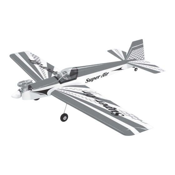
SPECIFICATION
Wingspan :
Length
Weight
Radio
Servo
Engine
Electric Motor :BL 2826/06 OUTRUNER
Battery :4 cells-Li-Poly-14.8V-5.000mAh
Speed control: 45A
Propeller : 12 x 8
Instruction Manual book
1.550 mm
:
1.250 mm
:
2.4 kg
:
04 channels.
:
05 servos.
:
40 - 46
52
61.02 in.
49.21 in.
5.28 Lbs.
2 stroke
4 stroke
Made in Vietnam.
Advertisement
Table of Contents

Subscribe to Our Youtube Channel
Related Manuals for Black Horse Model SUPER AIR BH.05


Summary of Contents for Black Horse Model SUPER AIR BH.05
- Page 1 Instruction Manual book SPECIFICATION Wingspan : 1.550 mm 61.02 in. Length 1.250 mm 49.21 in. Weight 2.4 kg 5.28 Lbs. Radio 04 channels.
- Page 2 SUPER AIR- Item code Instruction Manual BH05-A. This instruction manual is designed to help you build a great flying aeroplane. Please read this manual thoroughly before starting assembly of your SUPER AIR. Use the parts listing below to identify all parts. WARNING.
-
Page 3: Safety Precaution
SUPER AIR- Item code Instruction Manual BH05-A. Caution: this model is not a toy! Caution! do not heat the film more than is If you are a beginner to this type of powered absolutely necessary. If the air or the iron is model, please ask an experienced model flyer too hot, the film may melt and holes may be for help and support. -
Page 4: Installing The Aileron Servos
SUPER AIR- Item code Instruction Manual BH05-A. REPLACEMENT SMALL PARTS 3x15mm. 3x12mm. 1.Main landing gear(Left/Right). 2. Wheels. 3.Fuel Tank. Top side. 4. Tie wrap 5. Spinner. 6. Plastic parts for elevator and rudder pushrod. 7. Tail gear. 8.Electric motor ply of wood (8a,8b). Bottom side INSTALLING THE AILERON SERVOS. - Page 5 SUPER AIR- Item code Instruction Manual BH05-A. 3. Drill 1,5mm pilot holes through the block of wood for each of the four mounting screws provided with the servo. Install servo into ai- Temporary pin to leron servo tray as same as picture below. keep hinge centered.
- Page 6 SUPER AIR- Item code Instruction Manual BH05-A. 2. Locate nylon control horn, nylon con- trol horn backplates and 3 machine screws. 3. Drill through 1.5mm (diameter) the ai- leron using the control horn as a guide and screw the control horn in place. Repeat the procedure for the other wing half.
-
Page 7: Installing The Aileron Linkages
SUPER AIR- Item code Instruction Manual BH05-A. 4. Locate one nylon servo arm, and using wire cutters,remove all but one of the arms. Using a 2mm drill bit, enlarge the third hole out from the center of the arm to accommo- date the aileron pushrod wire. -
Page 8: Installing The Main Landing Gear
SUPER AIR- Item code Instruction Manual BH05-A. INSTALLING THE MAIN LANDING GEAR. 4x12mm 3x15mm 2. Using a modeling knife, remove the covering wing. Remove covering. Secure. Repeat the procedure for the other wing half. - Page 9 SUPER AIR- Item code Instruction Manual BH05-A. 3x15mm A+B Epoxy PLUS A+B Epoxy PLUS glue. Secure. 3x 15mm Bottom wing. secure.
-
Page 10: Installing The Engine Mount
SUPER AIR- Item code Instruction Manual BH05-A. Bottom wing. Epoxy glue Repeat the procedure for the other main gear wheel. INSTALLING THE ENGINE MOUNT. THERE ARE TWO OPTIONS: Front view 1. ELECTRIC MOTOR 2. ENGINE MOUNT. OPTION 1: ELECTRIC MOTOR. Secure 3x 15mm C/A glue... -
Page 11: Option 2: Engine Mount
SUPER AIR- Item code Instruction Manual BH05-A. Battery When the stopper assembly is installed in the tank, the top of the vent tube should rest just below the top surface of the tank. It should not touch the top of the tank. OPTION 2: ENGINE MOUNT. -
Page 12: Installing The Engine
SUPER AIR- Item code Instruction Manual BH05-A. 8. Feed three lines through the fuel tank compartment and through the pre-drilled hole Tie wrap. in the firewall. Pull the lines out from behind the engine, while guiding the fuel tank into place. -
Page 13: Installing The Throttle Servo
SUPER AIR- Item code Instruction Manual BH05-A. Drill a hole 2.5mm diameter INSTALLING THE THROTTLE SERVO. 1. Install one adjustable metal connector through the third hole out from the center of one servo arm, enlarge the hole in the servo arm using a 2mm drill bit to accommodate the servo connector. -
Page 14: Installing The Spinner
SUPER AIR- Item code Instruction Manual BH05-A. INSTALLING THE SPINNER. 3x 12mm Install the spinner backplate, propeller and spinner cone. The spinner cone is held in place using two 3mm x 12mm wood screws. secure. Throttle wire. Front view. - Page 15 SUPER AIR- Item code Instruction Manual BH05-A. ELEVATOR INSTALLATION. SERVO INSTALLATION. 1. Install the rubber grommets and brass collets into the elevator servo. Test fit the servo Cut the covering into the servo tray. away from the slot. 2. Mount the servo to the tray using the ...
- Page 16 SUPER AIR- Item code Instruction Manual BH05-A. Remove covering. Remove covering 5. When you are sure that everything is aligned correctly, mix up a generous amount of 30 minute epoxy. Apply a thin layer to the top and bottom of the stabilizer mounting area and to the stabilizer mounting platform sides in the fuselage.
-
Page 17: Elevator Control Horn Installation
SUPER AIR- Item code Instruction Manual BH05-A. ELEVATOR CONTROL HORN INSTALLATION. Elevator control horn install as same as the way of aileron control horn. Please see pic- tures below. Control horn of elevator. 2 x12mm. 6. After the epoxy has fully cured, remove the masking tape or T-pins used to hold the stabilizer in place and carefully inspect the glue joints. -
Page 18: Elevator Pushrod Installation
SUPER AIR- Item code Instruction Manual BH05-A. ELEVATOR PUSHROD INSTALLATION. Elevator servo. Elevator pushrod install as same as the way of aileron pushrod. Cut. Elevator servo. Elevator pushrod. Bottom side. Bend and cut after. Elevator Elevator pushrod. pushrod. Top side. Elevator pushrod. -
Page 19: Vertical Installation
SUPER AIR- Item code Instruction Manual BH05-A. VERTICAL INSTALLATION. See picture below: Secure. Hinge. Cut the covering away from the slot. RUDDER SERVO INSTALLATION. Temporary pin to Rudder servo install as same as method of keep hinge centered. elevator servo. See picture below: Rudder servo. - Page 20 SUPER AIR- Item code Instruction Manual BH05-A. 4. Now, remove the rudder and using a 1) Using a modeling knife, remove the modeling knife, carefully cut just inside the covering from the top of the fuselage and the marked lines and remove the film of the rud- covering from over the precut hinge slot cut der.
- Page 21 SUPER AIR- Item code Instruction Manual BH05-A. secure. RUDDER CONTROL HORN Rudder AND PUSHROD INSTALLATION. control horn. 1) Locate the two nylon control horns, two nylon control horn backplates and four M2 x 12mm machine screws. 2) Position the rudder horn on the bottom side of rudder.
- Page 22 SUPER AIR- Item code Instruction Manual BH05-A. Plastic parts of elevator and rudder pushrod. Cut. Bend and cut Elevator pushrod. Rudder pushrod. Bottom side. C/A glue. Snap keeper...
-
Page 23: Mounting The Tail Wheel Bracket
SUPER AIR- Item code Instruction Manual BH05-A. Bottom side. Drill hole MOUNTING THE TAIL WHEEL BRACKET. 3x12mm. 3. Secure the tail wheel bracket in place using three 3mm x 12mm wood screws. Be 1. Set the tail wheel assembly in place careful not to overtighten the screws. -
Page 24: Installing The Switch
SUPER AIR- Item code Instruction Manual BH05-A. INSTALLING THE SWITCH. 1. Cut out the switch hole using a modeling knife. Use a 2mm drill bit and drill out the two mounting holes through the fuselage side. Tie wrap. - Page 25 SUPER AIR- Item code Instruction Manual BH05-A. Right side. Secure. Secure. See picture wing attach to fuselage. Installing the fuselage hatch as same as pic- Left side. ture below. Top side. 3. Insert two wing panels as pictures below. Insert and secure...
-
Page 26: Control Throws
SUPER AIR- Item code Instruction Manual BH05-A. BALANCING. CONTROL THROWS. 1) It is critical that your airplane be bal- 1. We highly recommend setting up a plane anced correctly. Improper balance will cause using the control throws listed.
Need help?
Do you have a question about the SUPER AIR BH.05 and is the answer not in the manual?
Questions and answers