Table of Contents

Related Manuals for Black Horse Model AT.6-Texan


Summary of Contents for Black Horse Model AT.6-Texan
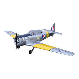
- Page 1 Instruction Manual book ITEM CODE BH61. SPECIFICATION Wingspan : 2,090mm 82.28 in. Length 1,470m 57.87 in. Weight 4.9 kg 10.78 Lbs. Radio 07 channels. Servo 09 servos. Engine 2 stroke. 20 CC gas. Made in Vietnam.
-
Page 2: Parts List
AT.6 TEXAN Instruction Manual This instruction manual is designed to help you build a great flying aeroplane. Please read this manual thoroughly before starting assembly of your AT.6- TEXAN. Use the parts listing below to identify all parts. WARNING Please be aware that this aeroplane is not a toy and if assembled or used incorrectly it is capable of causing injury to people or property. -
Page 3: Safety Precaution
AT.6 TEXAN. INSTRUCTION MANUAL Caution: this model is not a toy! SAFETY PRECAUTION. If you are a beginner to this type of powered + This is not a toy model, please ask an experienced model flyer + Be sure that no other flyers are using your for help and support. -
Page 4: Instruction Manual
AT.6 TEXAN Instruction Manual INSTALLING THE AILERON - FLAP SERVO CONTROL HORN. C/A glue Aileron Flap Bottom side C/A glue Aileron C/A glue C/A glue C/A glue C/A glue Flap... - Page 5 AT.6 TEXAN. INSTRUCTION MANUAL C/A glue Aileron Flap 3. Drill 1,5mm pilot holes through the block of wood for each of the four mounting screws INSTALLING THE AILERON SERVO . provided with the servo. Install servo into ai- 1. Install the rubber grommets and brass leron servo tray as same as picture below.
- Page 6 AT.6 TEXAN Instruction Manual Repeat the procedure for the other wing Electric wire half. INSTALLING THE AILERON CONTROL HORN. Nilon control clasp. 3 x 40mm 5. Instal servo tray with aileron servo into the wing as same as picture below. 2x10mm.
-
Page 7: Installing The Aileron Linkages
AT.6 TEXAN. INSTRUCTION MANUAL Install aileron control horn as same as picture below . Control horn of the aileron Repeat the procedure for the other wing half. INSTALLING THE AILERON LINKAGES. Installing the aileron linkages as pictures below. M3 lock nut... - Page 8 AT.6 TEXAN Instruction Manual INSTALLING THE FLAP SERVO . 2x10mm. Flap Bottom side INSTALLING THE FLAP CONTROL HORN. Nilon control clasp. 3 x 40mm Thread Thread Electric Remove covering wire Flap...
- Page 9 AT.6 TEXAN. INSTRUCTION MANUAL Aileron Flap Bottom Repeat the procedure for the other wing half. INSTALLING AIR RETRACTABLE LANDING GEAR. Bottom side Control horn of the flap Repeat the procedure for the other wing half. INSTALLING THE FLAP LINKAGES. Installing the aileron linkages as pictures below.
- Page 10 AT.6 TEXAN Instruction Manual...
- Page 11 AT.6 TEXAN. INSTRUCTION MANUAL Mark point 3 x 15mm Secure 4 x 35mm...
- Page 12 AT.6 TEXAN Instruction Manual Bottom side Top side Secure...
- Page 13 AT.6 TEXAN. INSTRUCTION MANUAL Valve control valve one way Air speed Secure control valve 3 way connector Air tank Air supply Valve one way Right main gear wing Left main gear wing Vavle control control valve Secure...
- Page 14 AT.6 TEXAN Instruction Manual Right side Air speed control valve Left side Top side Bottom side...
-
Page 15: Wing Attachment
AT.6 TEXAN. INSTRUCTION MANUAL WING ATTACHMENT. Locate the aluminium wing dihedral brace. *** Test fit the aluminium tube dihedral brace into each wing haft. The brace should slide in easily. If not, use 220 grit sand around the edges and ends of the brace until it fits prop- erly. -
Page 16: Installing The Engine Mount
AT.6 TEXAN Instruction Manual Secure Top side Drill a hole 2mm diameter Bottom side INSTALLING THE ENGINE MOUNT. ENGINE MOUNT. See pictures below: 4 x 30mm 4 x 30mm... -
Page 17: Installing The Stopper Assembly
AT.6 TEXAN. INSTRUCTION MANUAL FUEL TANK. INSTALLING THE STOPPER ASSEMBLY 1) The stopper has been pre-assembled at the factory. 2) Using a modeling knife, cut one length of silicon fuel line (the length of silicon fuel line is calculated by how the weighted clunk should rest about 8mm away from the rear of the tank and move freely inside the tank). -
Page 18: Installing The Engine
AT.6 TEXAN Instruction Manual Do not secure the tank into place perma- nently until after balancing the airplane. You may need to remove the tank to mount the battery in the fuel tank compartment INSTALLING THE ENGINE. Locate the long piece of wire used for the throttle pushrod. - Page 19 AT.6 TEXAN. INSTRUCTION MANUAL Right side Pushrod wire. Left side Pushrod w i r e . Pushrod w i r e . Secure...
- Page 20 AT.6 TEXAN Instruction Manual COWLING. 1) Slide the fiberglass cowl over the en- gine and line up the back edge of the cowl with the marks you made on the fuselage. Right side Bottom side 2) While keeping the back edge of the cowl flush with the marks, align the front of the cowl with the crankshaft of the engine.
-
Page 21: Installing The Throttle Pushrod
AT.6 TEXAN. INSTRUCTION MANUAL Bottom side 3 x 12mm Machine screw INSTALLING THE THROTTLE PUSHROD 1. Install one adjustable metal connector through the third hole out from the center of one servo arm, enlarge the hole in the servo arm using a 2mm drill bit to accommodate the servo connector. -
Page 22: Horizontal Stabilizer
AT.6 TEXAN Instruction Manual Secure HORIZONTAL STABILIZER. T h r o t t l e pushrod See pictures below: ELEVATOR INSTALLATION. SERVO INSTALLATION. Top side 1. Install the rubber grommets and brass collets into the elevator servo. Test fit the servo into the servo tray. - Page 23 AT.6 TEXAN. INSTRUCTION MANUAL C/A glue C/A glue 1. Draw a center line onto the horizontal stabilizer. Then slide the horizont al into the fuselage. C/A glue center line 2 Using a modeling knife, cut away the covering from the fuselage for the stabilizer and remove it.
- Page 24 AT.6 TEXAN Instruction Manual Check to mark sure the wing and stabi- lizer are paralell. If they are not, lightly sand the opening in the fuselage for the stabilizer until the stabilizer is paralell to the wing. Mark point Bottom side Epoxy glue 4.
-
Page 25: Elevator Control Horn Installation
AT.6 TEXAN. INSTRUCTION MANUAL C/A glue ELEVATOR CONTROL HORN INSTALLATION. Elevator control horn install as same as the way of aileron control horn. Please see pic- tures below. 3 x 40mm. Nilon control clasp. M3 lock nut. Control horn of elevator . Remove covering Bottom side Elevator... -
Page 26: Elevator Pushrod Installation
AT.6 TEXAN Instruction Manual Elevator Elevator control horn control horn ELEVATOR PUSHROD INSTALLATION. Pushrod install as same as method of pushrod wing. See pictures below: Elevator Elevator pushrod pushrod R e m o v e covering Bottom elevator Top elevator M2 lock nut... -
Page 27: Vertical Stabilizer
AT.6 TEXAN. INSTRUCTION MANUAL Elevator servo C/A glue Elevator servo VERTICAL STABILIZER. Rudder servo 1. Put the rudder into the fuselage as same as picture below. 2. Mark the shape of the vertical on the left and right side of the rudder on to the horizon- tal stabilizer using a felt-tip pen. - Page 28 AT.6 TEXAN Instruction Manual 4. Now , remove the rudder and using a modeling knife, carefully cut just inside the marked lines and remove the film of the rud- der. Just as you did with the horizontal stabi- lizer, make sure you only press hard enough to cut the film, not the balsa rudder.
-
Page 29: Rudder Pushrod Installation
AT.6 TEXAN. INSTRUCTION MANUAL Control horn of Rudder . RUDDER PUSHROD INSTALLATION. 1. Rudder pushrod install as same as the way of aileron control horn. 2. Rudder push - pull system install as same as picture below. M3 clevis ( 4pcs for push - pull system ). C/A glue M3 lock nut. - Page 30 AT.6 TEXAN Instruction Manual Rudder Rudder pushrod pushrod C/A glue Rudder Rudder control horn control horn...
-
Page 31: Mounting The Tail Wheel Bracket
AT.6 TEXAN. INSTRUCTION MANUAL MOUNTING THE TAIL WHEEL BRACKET. 3 x 12mm Rudder push 3 x 15mm pull cable Mark point Secure Mark point... -
Page 32: Installing The Switch
AT.6 TEXAN Instruction Manual Air tank Secure Air tank Elevator pushrod Rudder pushrod Rudder pushrod Elevator pushrod Air tank INSTALLING THE AIR TANK. Tie wrap. Air supply Tie wrap. INSTALLING THE SWITCH. 1) Cut out the switch hole using a modeling knife. -
Page 33: Installing The Receiver And Battery
AT.6 TEXAN. INSTRUCTION MANUAL Receiver switch INSTALLING THE RECEIVER AND BATTERY. 1. Plug the servo leads and the switch lead into the receiver . You may want to plug an aileron extension into the receiver to make plugging in the aileron servo lead easier when you are installing the wing . - Page 34 AT.6 TEXAN Instruction Manual See picture wing attach to fuselage. Wing bolt. C/A glue Installing the fuselage hatch as same as pic- ture below. Insert and secure...
- Page 35 AT.6 TEXAN. INSTRUCTION MANUAL Top fuselage C/A glue Drill a hole 6mm diameter. C/A glue C/A glue...
- Page 36 AT.6 TEXAN Instruction Manual C/A glue C/A glue Mark point Mark point C/A glue...
- Page 37 AT.6 TEXAN. INSTRUCTION MANUAL BALANCING. 1) It is critical that your airplane be bal- anced correctly. Improper balance will cause your plane to lose control and crash. THE CENTER OF GRA VITY IS LOCA TED 175MM BACK FROM THE LEADING EDGE OF THE WING.
-
Page 38: Control Throws
AT.6 TEXAN Instruction Manual CONTROL THROWS. 1) We highly recommend setting up a plane using the control throws listed. 2) The control throws should be meas- ured at the widest point of each control sur- face. 3) Check to be sure the control surfaces move in the correct directions. - Page 39 AT.6 TEXAN. INSTRUCTION MANUAL...
- Page 40 AT.6 TEXAN Instruction Manual...
- Page 41 AT.6 TEXAN. INSTRUCTION MANUAL...
- Page 42 AT.6 TEXAN Instruction Manual...
- Page 43 AT.6 TEXAN. INSTRUCTION MANUAL...
- Page 44 AT.6 TEXAN Instruction Manual...
- Page 45 AT.6 TEXAN. INSTRUCTION MANUAL...
- Page 46 AT.6 TEXAN Instruction Manual...
Need help?
Do you have a question about the AT.6-Texan and is the answer not in the manual?
Questions and answers