
Related Manuals for Black Horse Model Travel Air BH.06


Summary of Contents for Black Horse Model Travel Air BH.06
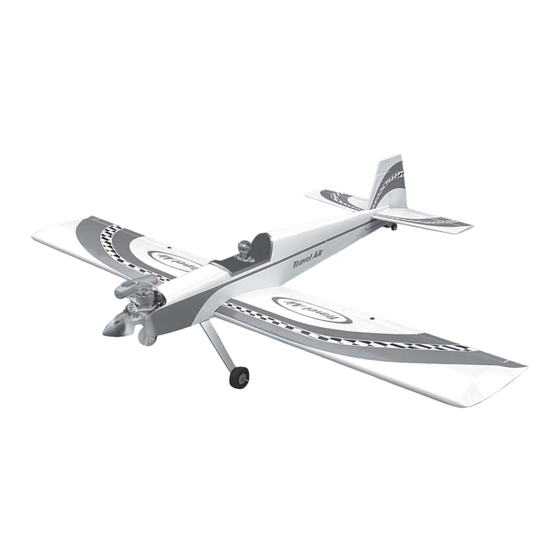
- Page 1 Instruction Manual book SPECIFICATION Wingspan : 1,550 mm 61.02 in. Length 1,250 mm 49.2 in. Weight 2.4 kg 5.28 Lbs. Radio 04 channels. Servo 05 servos. Engine 40 - 46 2 stroke 4 stroke Made in Vietnam.
- Page 2 TRAVEL AIR. Instruction Manual This instruction manual is designed to help you build a great flying aeroplane. Please read this manual thoroughly before starting assembly of your TRAVEL AIR. Use the parts listing below to identify all parts. WARNING. Please be aware that this aeroplane is not a toy and if assembled or used incorrectly it is capable of causing injury to people or property.
-
Page 3: Safety Precaution
TRAVEL AIR. INSTRUCTION MANUAL 2. Using a modeling knife, remove the SAFETY PRECAUTION. covering servo tray. + This is not a toy + Be sure that no other flyers are using your radio frequency. + Do not smoke near fuel + Store fuel in a cool, dry place, away from children and pets. - Page 4 TRAVEL AIR. Instruction Manual 2x10mm. Electric wire. Repeat the procedure for the other wing half. INSTALLING THE AILERON CONTROL HORN. 5. Instal servo tray with aileron servo into the wing as same as picture below. Nilon control clasp. M3 lock nut. 3x40mm.
- Page 5 TRAVEL AIR. INSTRUCTION MANUAL Bottom side. 2. Drill through 6mm (diameter) the aileron using the control horn as a guide and screw the control horn in place. aileron 3. Install control horn as same as picture below.
-
Page 6: Installing The Aileron Linkages
TRAVEL AIR. Instruction Manual 3. Plug the aileron servo into the receiver and center the servo. Install the servo arm onto the servo. The servo arm should be C/A glue perpendicular to the servo and point toward the middle of the wing. Bend and cut after. -
Page 7: Joining The Wing Halves
TRAVEL AIR. INSTRUCTION MANUAL Top side. JOINING THE WING HALVES. 1. Locate the aluminium wing dihedral brace. 2. Using a modeling knife, remove the covering wing. Remove covering. Masking tape. Apply masking tape. 3. Test fit the dihedral brace into each wing half. -
Page 8: Installing The Engine Mount
TRAVEL AIR. Instruction Manual INSTALLING THE ENGINE MOUNT. 5. Test fit the stopper assembly into the tank. It may be necessary to remove some of the flashing around the tank opening using a modeling knife. If flashing is present, make FUEL TANK. -
Page 9: Installing The Engine
TRAVEL AIR. INSTRUCTION MANUAL Fuel tank. Blow through one of the lines to ensure the fuel lines have not become kinked inside the fuel tank compartment. Air should flow through easily. 9. To secure the fuel tank in place, apply a bead of silicon sealer to the forward area of the tank, where it exits the fuselage behind the engine mounting box and to the rear of the tank... -
Page 10: Installing The Spinner
TRAVEL AIR. Instruction Manual Pushrod wire INSTALLING THE SPINNER. Install the spinner backplate, propeller and spinner cone. The spinner cone is held in place using two 3mm x 12mm wood screws. -
Page 11: Horizontal Stabilizer Installation
TRAVEL AIR. INSTRUCTION MANUAL Elevator servo. HORIZONTAL STABILIZER INSTALLATION. 1. Using a modeling knife, cut away the covering from the fuselage for the stabilizer and remove it. 2 . Draw a center line onto the horizontal stabilizer. Then slide the horizontal into the fuselage. -
Page 12: Elevator Control Horn Installation
TRAVEL AIR. Instruction Manual in the fuselage. Slide the stabilizer in place and re-align. Double check all of your measurements one more time before the epoxy cures. Remove any excess epoxy using a paper towel and rubbing alcohol and hold the stabilizer in place with T-pins or masking tape. -
Page 13: Elevator Pushrod Installation
TRAVEL AIR. INSTRUCTION MANUAL C/A glue Drill 1 hole with 6 mm diameter. ELEVATOR PUSHROD INSTALLATION. Elevator pushrod install as same as the way of aileron pushrod. Please see pictures below. - Page 14 TRAVEL AIR. Instruction Manual Ben and cut. Elevator pushrod. Secure. Elevator pushrod. Elevator servo. Cut. Secure.
-
Page 15: Vertical Installation
TRAVEL AIR. INSTRUCTION MANUAL 3. Mark the shape of the vertical on the left VERTICAL INSTALLATION. and right side on the rudder using a felt-tip pen. Pen. 4. Now, remove the rudder and using a modeling knife, carefully cut just inside the marked lines and remove the film of the rud- der. - Page 16 TRAVEL AIR. Instruction Manual 6) When you are sure that everything is a Nilon aligned correctly, mix up a generous amount M3 lock nut control clasp. of 30 minute epoxy. Apply a thin layer to the slot in the mounting platform and to the verti- cal stabilizer mounting area.
-
Page 17: Rudder Pushrod Installation
TRAVEL AIR. INSTRUCTION MANUAL RUDDER PUSHROD INSTALLATION. Rudder pushrod install as same as the way of aileron pushrod. C/A glue Bend and cut after C/A glue Rudder control horn. Snap keeper. Rudder pushrod. Elevator pushrod. Elevator Elevator pushrod. pushrod. Rudder Rudder pushrod. -
Page 18: Installing The Switch
TRAVEL AIR. Instruction Manual INSTALLING THE SWITCH. INSTALLING THE THROTTLE PUSHROD. 1. Cut out the switch hole using a modeling 1. Install one adjustable metal connector knife. Use a 2mm drill bit and drill out the two through the third hole out from the center of mounting holes through the fuselage side. - Page 19 TRAVEL AIR. INSTRUCTION MANUAL INSTALLING THE RECEIVER AND BATTERY. 1. Plug the servo leads and the switch lead into the receiver. You may want to plug an aileron extension into the receiver to make plugging in the aileron servo lead easier when you are installing the wing .
-
Page 20: Mounting The Tail Wheel Bracket
TRAVEL AIR. Instruction Manual 2) Using the hardware provided, mount the main landing gear to the fuselage. Secure. Repeat the process for the other wheel. MOUNTING THE TAIL WHEEL BRACKET. 3x12mm. 1. Set the tail wheel assembly in place on the plywood plate. The pivot point of the tail wheel wire should be even with the rud- der hinge line and the tail wheel bracket should be centered on the plywood plate. -
Page 21: Wing Attachment
TRAVEL AIR. INSTRUCTION MANUAL WING ATTACHMENT. See pictures below: Wing bolt. Wing attach to fuselage. Top side. 2. Using a pen, mark the locations of the two mounting screws. Remove the tail wheel Bottom side. bracket and drill 1mm pilot holes at the loca- tions marked. - Page 22 TRAVEL AIR. Instruction Manual With the wing attached to the fuselage, all parts of the model installed ( ready to fly), and empty fuel tanks, hold the model at the marked balance point with the stabilizer level. Lift the model. If the tail drops when you lift, the model is “tail heavy”...
-
Page 23: Control Throws
TRAVEL AIR. INSTRUCTION MANUAL CONTROL THROWS. 1. We highly recommend setting up a plane using the control throws listed. 2. The control throws should be measured at the widest point of each control surface. 3. Check to be sure the control surfaces move in the correct directions.
Need help?
Do you have a question about the Travel Air BH.06 and is the answer not in the manual?
Questions and answers