Table of Contents
Advertisement
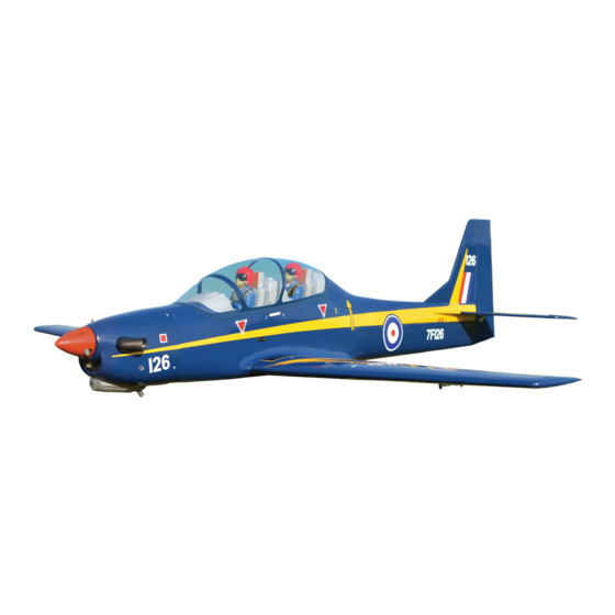
SUPER TUCANO
SUPER TUCANO
Glow and EP
OPTION ELECTRIC RETRACT GEAR (NOT INCLUDING).
ONLY INCLUDING CNC SUSPENSION METAL STRUTS.
ALL BALSA – PLYWOOD CONSTRUCTION.
COVERED WITH ORACOVER.
95% ALMOST READY TO FLY
SPECIFICATION
- Wingspan:1,730 mm (68.1in).
- Length: 1,752 mm (67in).
- Weight: 4.7 kg (10.34lbs).
- Wing area: 47.6 dm
- Wing loading: 98.74.g/dm
- Servo mount: 42mm x 21mm.
- Spinner: 70mm
- Wing type: NacaAirfoil.
- Gear type: Electric retract gear,
size: (92.2 x 51 x 30.6)mm(not included).
CNC Suspension Metal Struts (included).
Instruction Manual Book
.
2
.
2
Item code: BH173
Parts listing required (not included):
- Radio: 07 channels.
- Servo: 08 servos.
- Engine: 65-95 2 stroke, 15cc gas.
- Motor: Brushless Outrunner 1200-2200W, 650KV.
- Propeller: Suit with your engine.
Recommended motor and battery set up (not
included):
- Motor: RIMFIRE.60.
- Lipo cell: 6 cells 4,000-5,000mAh.
- Receiver battery: 6V/ 1200-2000mAh.
- ESC: 80A.
Made in Vietnam
Advertisement
Table of Contents

Related Manuals for Black Horse Model SUPER TUCANO BH173


Summary of Contents for Black Horse Model SUPER TUCANO BH173
- Page 1 Instruction Manual Book Item code: BH173 SUPER TUCANO SUPER TUCANO Glow and EP OPTION ELECTRIC RETRACT GEAR (NOT INCLUDING). ONLY INCLUDING CNC SUSPENSION METAL STRUTS. ALL BALSA – PLYWOOD CONSTRUCTION. COVERED WITH ORACOVER. 95% ALMOST READY TO FLY SPECIFICATION - Wingspan:1,730 mm (68.1in). Parts listing required (not included): - Length: 1,752 mm (67in).
-
Page 2: Table Of Contents
Item code: BH173 INSTRUCTION MANUAL SUPER TUCANO TABLE OF CONTENTS Mounting the cowl..........21 Symbols used throughout this instruction Installing the nose gear........23 manual, comprise............2 Warranty..............3 Installing horizontal stabilizer......26 Installing the control horns and linkages..27 Disclaimer..............3 Installing the vertical stabilizer......28 Suggestion..............3 Installing the switch, receiver and battery...29 Note................3 Wing attachment..........30... -
Page 3: Warranty
The the use or misuse of Black Horse Model products. By the model will only be strong and fly well if you complete your... -
Page 4: Part Listing ( Not Included )
Item code: BH173 INSTRUCTION MANUAL SUPER TUCANO PARTS LISTING (NOT INCLUDED). Servo extension leads....pcs....1 pcs. Engine: 65 - 95 ..1 pcs. 220mm ..2 pcs. 190mm ..2 pcs. Size: (92.2 x 51 x 30.6)mm. Propeller. - Page 5 Item code: BH173 INSTRUCTION MANUAL SUPER TUCANO : Fuselage : Wing panel ( 2a, 2b . : Cockpit fuselage ( Canopy, 3b : Pilot, : Cockpit). : Horizontal stabilizer. ertical stabilizer : Cowling. : Spinner. : Aluminium wing dihedral brace. Plastic - engine mount (9a, 9b) : Wheel well (10a, 10b, 10c) .
-
Page 6: Preparations
Item code: BH173 INSTRUCTION MANUAL SUPER TUCANO PREPARATIONS: Use a covering iron with a covering sock on high heat to tighten the covering if necessary. Apply pressure over sheeted areas to thoroughly bond the covering to the wood. INSTALLING THE AILERONS AND FLAPS. Apply drops of thin CA to the top and bottom of each hinge. - Page 7 Item code: BH173 INSTRUCTION MANUAL SUPER TUCANO 5. Place the servo into the servo tray/ hatch into the 6. Repeat step # 2 - # 5 to install the second aileron servo box on the bottom of the wing and drill 1.5mm servo in the opposite wing half.
-
Page 8: Installing The Control Horns And Linkages
Item code: BH173 INSTRUCTION MANUAL SUPER TUCANO INSTALLING THE CONTROL HORNS AND LINKAGES Nylon Clevis - - - - - - - 4 100mm Push rod - - 4 Flaslink Horn - - - - - - - 4 Horn - - - - - - 4 1.7x8 mm Cap Screw - - - - - - 4... - Page 9 Item code: BH173 INSTRUCTION MANUAL SUPER TUCANO Nylon Clevis 1.7x8mm Cap Screw Bottom view...
-
Page 10: Installing The Wheel Well
Item code: BH173 INSTRUCTION MANUAL SUPER TUCANO INSTALLING THE WHEEL WELL Using a modeling knife, Wheel well carefully remove the film covering from the gear tray. Make sure that Cut the plastic Cut the plastic you do not remove any wood. Bottom view... -
Page 11: Installing Main Gear
Item code: BH173 INSTRUCTION MANUAL SUPER TUCANO Fuselage Bottom Side INSTALLING MAIN GEAR 3x15mm Tp Screw Cab link ELECTRIC NOT INCLUDED. - - 12 - - - - - 2 Metal Clevis 5x35mm Socket Head Cap Screw - - - - - 2 - - - - - - 3 600mm... - Page 12 Item code: BH173 INSTRUCTION MANUAL SUPER TUCANO 5mm Washer ONLY INCLUDING OLEO STRUTS. 5x35mm Landing gear mount. Screw 4x4mm 75mm Wheels. Spring 3x6mm Main gear Nose gear 65mm Wheels. Main gear THERE ARE TWO OPTIONS: Nose gear OPTION 1: MAIN GEAR STRUTS Screw Bottom view C .
- Page 13 Item code: BH173 INSTRUCTION MANUAL SUPER TUCANO Screw the gear in position Bottom view OPTION 2: ELECTRIC GEAR RETRACTS Screw Bottom view...
- Page 14 Item code: BH173 INSTRUCTION MANUAL SUPER TUCANO Screw the gear in position...
-
Page 15: Installing The Fuselage Servos
Item code: BH173 INSTRUCTION MANUAL SUPER TUCANO INSTALLING THE FUSELAGE SERVOS 1) Install the rubber grommets and brass collets into the elevator, rudder and throttle servos. Test fit the servos into the servo tray. Trim the tray if necessary to fit your servos. 2) Mount the servo to the tray using the mounting screws provided with your radio system. -
Page 16: Installing The Engine Mount
Item code: BH173 INSTRUCTION MANUAL SUPER TUCANO INSTALLING THE ENGINE MOUNT There are two options: 1. Electric motor 2. Engine mount. OPTION 1: INSTALLING THE ELECTRIC MOTOR (EP VERSION) M4 Blind Nut - - - - - 4 M4 Blind Nut 10x5mm Aluminum - - - - - 4 10x50mm Aluminum... -
Page 17: Engine Installation
Item code: BH173 INSTRUCTION MANUAL SUPER TUCANO OPTION 2: ENGINE INSTALLATION 4) Carefully bend the third nylon tube down at a 45 degree angle (using a cigarette lighter). This tube will Installing the engine mount, fuel tank be vent tube to the fueling valve. When the stopper assembly is installed in the tank, the top of the vent tube should rest just below the top surface of the tank. -
Page 18: Installing The Throttle Pushrod
Item code: BH173 INSTRUCTION MANUAL SUPER TUCANO Fuel tank 7) Using a modeling knife, cut 3 lengths of fuel line 150mm long. Connect 2 lines to the 2 vent tubes and 1 line to the fuel pickup tube in the stopper. 8) Feed three lines through the fuel tank compartment and through the pre-drilled hole in the firewall. - Page 19 Item code: BH173 INSTRUCTION MANUAL SUPER TUCANO 4x30 mm Cap Screw 4mm Hex Nut - - - - - - - - 8 - - - - - - 4 4mm Flat Washer 4mm Hex Nut - - - - - - 4 4mm Flat Washer 4x30 mm Cap Screw 125 mm...
- Page 20 Item code: BH173 INSTRUCTION MANUAL SUPER TUCANO Connector - - - - 1 1) Install one adjustable metal connector through reverse the direction of the servo, using the the third hole out from the center of one servo arm, transmitter. enlarge the hole in the servo arm using a 2mm drill Slide the adjustable metal connector / servo bit to accommodate the servo connector.
-
Page 21: Mounting The Cowl
Item code: BH173 INSTRUCTION MANUAL SUPER TUCANO MOUNTING THE COWL Enlarging the holes through the cowl will prevent berglass from splitting when the mounting Remove the muf f ler and needle valve screws are installed. assembly from the engine. Slide the fiberglass cowl over the engine. - Page 22 Item code: BH173 INSTRUCTION MANUAL SUPER TUCANO C . A 2 m m 3x12mm Tp Screw C . A 3x12mm Tp Screw...
-
Page 23: Installing The Nose Gear
Item code: BH173 INSTRUCTION MANUAL SUPER TUCANO INSTALLING THE NOSE GEAR OPTION 1: NOSE GEAR STRUT Screw Crimp Cable rod 2.5mm... - Page 24 Item code: BH173 INSTRUCTION MANUAL SUPER TUCANO OPTION 2: ELECTRIC GEAR RETRACTS Screw 3x6 mm Screw Cable rod Screw Crimp 3x15mm 2.5mm...
- Page 25 Item code: BH173 INSTRUCTION MANUAL SUPER TUCANO Screw the gear in position Metal Clevis Cab link Servo nose gear Fuselage bottom side Servo nose gear...
-
Page 26: Installing Horizontal Stabilizer
Item code: BH173 INSTRUCTION MANUAL SUPER TUCANO INSTALLING HORIZONTAL STABILIZER Elevator install as same as the way of aileron. When cutting through the covering to remove it, cut with only enough pressure to only cut through the covering it's self. Cutting into the balsa structure may weaken it. -
Page 27: Installing The Control Horns And Linkages
Item code: BH173 INSTRUCTION MANUAL SUPER TUCANO INSTALLING THE CONTROL HORNS AND LINKAGES. Nylon Clevis Horn Nylon Clevis - - - - - - - 2 2.5mm 100mm Push rod - - 2 Flaslink - - - - - - - 2 Horn - - - - - - 2 1.7x8 mm Cap Screw... -
Page 28: Installing The Vertical Stabilizer
Item code: BH173 INSTRUCTION MANUAL SUPER TUCANO INSTALLATION THE VERTICAL STABILIZER Hinges for Rudder are glued the same way as the aileron before (see page 6, 7). INSTALLING THE CONTROL HORNS AND LINKAGES. Control horn and linkages for Rudder are installed the same way as the elevator before ( see page 8, 9 ). Nylon Clevis Nylon Clevis - - - - - - - 1... -
Page 29: Installing The Switch, Receiver And Battery
Item code: BH173 INSTRUCTION MANUAL SUPER TUCANO Flaslink Horn INSTALLING THE SWITCH, RECEIVER AND BATTERY INSTALLING THE SWITCH 1) Plug the servo leads and the switch lead into the receiver. You may want to plug an aileron extension 1) The switch should be mounted on the fuselage into the receiver to make plugging in the aileron servo side, opposite the muffler, close enough to the lead easier when you are installing the wing. -
Page 30: Wing Attachment
Item code: BH173 INSTRUCTION MANUAL SUPER TUCANO *** Test fit the aluminium tube dihedral brace into each WING ATTACHMENT wing haft. The brace should slide in easily. If not, use Locate the aluminium wing dihedral brace. 220 grit sand around the edges and ends of the brace until it fits properly. - Page 31 Item code: BH173 INSTRUCTION MANUAL SUPER TUCANO Screw the wing panel in position. 4x15mm Screw Repeat the procedure for the other wing half.
-
Page 32: Installing Cockpit Fuselage
Item code: BH173 INSTRUCTION MANUAL SUPER TUCANO INSTALLING COCKPIT FUSELAGE Position the canopy so the rear frame on the canopy is aligned with the rear edge of the cockpit opening. Use canopy glue to secure the canopy to the canopy hatch. Use low-tack tape to hold the canopy in position until the glue fully cures. - Page 33 Item code: BH173 INSTRUCTION MANUAL SUPER TUCANO C . A Open/Close Adhesive tape.
-
Page 34: Installing The Spinner, Propeller
Item code: BH173 INSTRUCTION MANUAL SUPER TUCANO INSTALLING THE SPINNER, PROPELLER * Install the spinner back-plate, propeller and spinner cone. The spinner cone is held in place using two screws. The propeller should not touch any part of the The propeller should not touch any part of the spinner - - - - - 1 cone. - Page 35 Item code: BH173 INSTRUCTION MANUAL SUPER TUCANO 3x12 mm Tp Screw...
-
Page 36: Balancing
Item code: BH173 INSTRUCTION MANUAL SUPER TUCANO If one side of the wing fall, that side is heavier BALANCING than the opposite. Add small amounts of lead weight to the bottom side of the lighter wing half's It is critical that your airplane be balanced wing tip. -
Page 37: For Your Radio Installation Basic Connection For Airplane And Adjustment Of Servos
Item code: BH173 INSTRUCTION MANUAL SUPER TUCANO FOR YOUR RADIO INSTALLATION BASIC CONNECTION FOR AIRPLANE AND ADJUSTMENT OF SERVOS Example of connection For more information, refer to radio system instruction manual. Follow instruction manual of Engine and Battery. Aileron Servo Aileron Aileron Servo Aileron... -
Page 38: Main Gear Dimensional Detail
Item code: BH173 INSTRUCTION MANUAL SUPER TUCANO MAIN GEAR DIMENSIONAL DETAIL NOSE GEAR STRUTS MAIN GEAR STRUTS LANDING GEAR MOUNT. . 41mm 31mm 44mm 5.1mm hold 5.1mm hold 25mm 21mm... -
Page 39: Decoration
Item code: BH173 INSTRUCTION MANUAL SUPER TUCANO DECORATION < Top view > < Bottom view > < Side view > Left < Side view > Right ORACCOVER #21-019 - Corsair Blue #21-030 - Cub Yellow... - Page 40 Item code: BH173 INSTRUCTION MANUAL SUPER TUCANO DECAL SHEET 11b 11c 17a 17b...
- Page 42 I/C FLYING WARNINGS Always operate in open areas, away from fly near power lines,aerials or AL WAYS adjust the engine from behind NEVER factories, hospitals, schools, buildings other dangerous areas including airports, the propeller, and do not allow any part of and houses etc.
- Page 43 I/C FLYING GUIDELINES Operate the control sticks on the ALWAYS land the model INTO When ready to fly, first extend transmitter and check that the the wind, this ensures that the the transmitter aerial. control surfaces move freely and in model lands at the slowest possible the CORRECT directions.