Table of Contents
Advertisement
Quick Links
Instruction Manual book
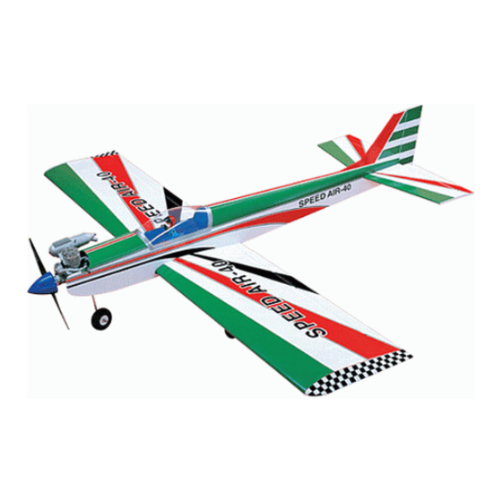
SPECIFICATION
Wingspan :
Length
Weight
Radio
Servo
Engine
Recommended Motor Size :Power 46
Battery :4 cells-Li-Poly-14.8V-4.000mAh
All manuals and user guides at all-guides.com
1,500 mm
:
1,160 mm
:
2.4 kg
:
04 channels.
:
05 servos.
:
40 - 46
52
59 in.
46 in.
5.28 Lbs.
2 stroke
4 stroke
Made in Vietnam.
Advertisement
Table of Contents

Subscribe to Our Youtube Channel
Related Manuals for Black Horse Model SPEED AIR-40


Summary of Contents for Black Horse Model SPEED AIR-40
- Page 1 All manuals and user guides at all-guides.com Instruction Manual book SPECIFICATION Wingspan : 1,500 mm 59 in. Length 1,160 mm 46 in. Weight 2.4 kg 5.28 Lbs.
- Page 2 Instruction Manual. Item code:BH08. This instruction manual is designed to help you build a great flying aeroplane. Please read this manual thoroughly before starting assembly of your SPEED AIR-40. Use the parts listing below to identify all parts. WARNING. Please be aware that this aeroplane is not a toy and if assembled or used incorrectly it is capable of causing injury to people or property.
-
Page 3: Safety Precaution
All manuals and user guides at all-guides.com SPEED AIR-40 _ Instruction Manual. Item code:BH08. Caution: this model is not a toy! Caution! do not heat the film more than is If you are a beginner to this type of powered absolutely necessary. -
Page 4: Servo Installation
All manuals and user guides at all-guides.com SPEED AIR-40 _ Instruction Manual. Item code:BH08. REPLACEMENT SMALL PARTS 3x15mm 3x12mm 1. Main landing gear. 2. Nose gear 3.Steering arm. 4. Fuel Tank. 5. Wheels. 6. Spinner. Top side 7. Plastic parts for elevator and rudder pushrod. - Page 5 All manuals and user guides at all-guides.com SPEED AIR-40 _ Instruction Manual. Item code:BH08. R e m o v e covering. Cut the covering away from the slot. Servo tray Temporary pin to keep hinge centered. 3. Drill 1,5mm pilot holes through the block...
- Page 6 All manuals and user guides at all-guides.com SPEED AIR-40 _ Instruction Manual. Item code:BH08. INSTALLING THE AILERON CONTROL HORN. Electric wire. Install aileron control horn as same as picture below. 2 x16mm. Control horn of Aileron 5. Instal servo tray with aileron servo into the wing as same as picture below.
-
Page 7: Installing The Aileron Linkages
All manuals and user guides at all-guides.com SPEED AIR-40 _ Instruction Manual. Item code:BH08. 3. Plug the aileron servo into the receiver and center the servo. Install the servo arm onto the servo. The servo arm should be perpen- dicular to the servo and point toward the mid- dle of the wing. - Page 8 All manuals and user guides at all-guides.com SPEED AIR-40 _ Instruction Manual. Item code:BH08. A+B Epoxy PLUS Aileron pushrod. Bottom side. 3x15mm Repeat the procedure for the other wing half. MAIN GEAR INSTALATION. PARTS REQUIRED A+B Epoxy PLUS Glue 3x15mm Remove covering.
-
Page 9: Installing The Engine Mount
All manuals and user guides at all-guides.com SPEED AIR-40 _ Instruction Manual. Item code:BH08. INSTALLING THE ENGINE MOUNT. Front view. NOSE GEAR INSTALLATION. Secure. Installing steering arm as follow Steering arm. Adjust the nose gear steering arm until the arm is parallel with the fire wall. - Page 10 All manuals and user guides at all-guides.com SPEED AIR-40 _ Instruction Manual. Item code:BH08. Secure. Front view. Secure.
-
Page 11: Installing The Engine
All manuals and user guides at all-guides.com SPEED AIR-40 _ Instruction Manual. Item code:BH08. INSTALLING THE ENGINE. Locate the long piece of wire used for the throttle pushrod. One end of the wire has been pre-bend in to a “Z” bend at the factory. This “Z”... - Page 12 All manuals and user guides at all-guides.com SPEED AIR-40 _ Instruction Manual. Item code:BH08. 3) Carefully bend the second nylon tube up at 6) When satisfied with the alignment of the a 45 degree angle (using a cigarette lighter). stopper assembly tighten the 3mm x 20mm This tube will be the vent tube to the muffler.
-
Page 13: Installing The Throttle Servo
All manuals and user guides at all-guides.com SPEED AIR-40 _ Instruction Manual. Item code:BH08. Tie wrap Throttle servo INSTALLING THE THROTTLE SERVO. Throttle wire. 1. Install one adjustable metal connector through the third hole out from the center of... -
Page 14: Installing The Spinner
All manuals and user guides at all-guides.com SPEED AIR-40 _ Instruction Manual. Item code:BH08. INSTALLING THE SPINNER. 3x 12mm Install the spinner backplate, propeller and spinner cone. The spinner cone is held in place using two 3mm x 12mm wood screws. -
Page 15: Horizontal Stabilizer Installation
All manuals and user guides at all-guides.com SPEED AIR-40 _ Instruction Manual. Item code:BH08. 1. Using a modeling knife, cut away the HORIZONTAL STABILIZER INSTALLATION. covering from the fuselage for the stabilizer See pictures below: and remove it. Top side... - Page 16 All manuals and user guides at all-guides.com SPEED AIR-40 _ Instruction Manual. Item code:BH08. Bottom side. 3. With the stabilizer held firmly in place, use a pen and draw lines onto the stabilizer When cutting through the covering to re- move it, cut with only enough pressure to where it and the fuselage sides meet.
-
Page 17: Elevator Control Horn Installa- Tion
All manuals and user guides at all-guides.com SPEED AIR-40 _ Instruction Manual. Item code:BH08. 7) After the epoxy has fully cured, remove ELEVATOR CONTROL HORN INSTALLA- the masking tape or T-pins used to hold the TION. -
Page 18: Elevator Pushrod Installation
All manuals and user guides at all-guides.com SPEED AIR-40 _ Instruction Manual. Item code:BH08. 2) Install control horn as same as picture Top side below. Control horn of elevator. Elevator servo. ELEVATOR PUSHROD INSTALLATION. Elevator pushrod install as same as the way of aileron pushrod. -
Page 19: Rudder Servo Installation
All manuals and user guides at all-guides.com SPEED AIR-40 _ Instruction Manual. Item code:BH08. Cut the covering away from the slot. RUDDER SERVO INSTALLATION. Rudder servo install as same as method of elevator servo. See picture below: Temporary pin to keep hinge centered. - Page 20 All manuals and user guides at all-guides.com SPEED AIR-40 _ Instruction Manual. Item code:BH08. 4) Now, remove the vertical stabilizer and using a modeling knife, carefully cut just in- side the marked lines and remove the film of the vertical stabilizer. Just as you did with the...
- Page 21 All manuals and user guides at all-guides.com SPEED AIR-40 _ Instruction Manual. Item code:BH08. Epoxy glue. C/A glue. 6) When you are sure that everything is a aligned correctly, mix up a generous amount of 30 minute epoxy. Apply a thin layer to the slot in the mounting platform and to the verti- cal stabilizer mounting area.
- Page 22 All manuals and user guides at all-guides.com SPEED AIR-40 _ Instruction Manual. Item code:BH08. Secure. Rudder pushrod. connector. servo arm Nose gear pushrod. Rudder control horn. Bend and cut Rudder pushrod. Rudder pushrod.
- Page 23 All manuals and user guides at all-guides.com SPEED AIR-40 _ Instruction Manual. Item code:BH08. Plastic parts of elevator and rudder pushrod. Snap keeper Cut. Secure. C/A glue. Nose gear pushrod. Elevator Elevator Bottom side. pushrod. pushrod. Rudder pushrod. Bottom side.
-
Page 24: Installing The Switch
All manuals and user guides at all-guides.com SPEED AIR-40 _ Instruction Manual. Item code:BH08. INSTALLING THE SWITCH. 1. Cut out the switch hole using a modeling knife. Use a 2mm drill bit and drill out the two mounting holes through the fuselage side. - Page 25 All manuals and user guides at all-guides.com SPEED AIR-40 _ Instruction Manual. Item code:BH08. Right side. Secure. Secure. See picture wing attach to fuselage. Installing the fuselage hatch as same as pic- ture below. Top side. Left side. 3. Insert two wing panels as pictures below.
-
Page 26: Control Throws
All manuals and user guides at all-guides.com SPEED AIR-40 _ Instruction Manual. Item code:BH08. BALANCING. CONTROL THROWS. 1) It is critical that your airplane be bal- 1) We highly recommend setting up a plane anced correctly.
Need help?
Do you have a question about the SPEED AIR-40 and is the answer not in the manual?
Questions and answers