Table of Contents
Advertisement
Quick Links
Advertisement
Table of Contents

Related Manuals for Black Horse Model PZL-104 WILGA BH 124


Summary of Contents for Black Horse Model PZL-104 WILGA BH 124
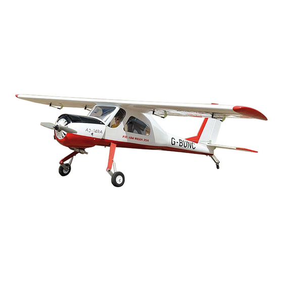
- Page 1 Instruction Manual book ITEM CODE:BH 124 SPECIFICATION Wingspan : 2,240 mm 88.19 in. Length 1,625 mm 63.98 in. Weight 6,4 kg 14.08 lbs. Parts listing required (not included). Radio 08 channels. Servo 09 standard high torque servos. Engine 26 - 35cc Gas. Made in Vietnam.
-
Page 2: Parts List
PZL-104 Wilga Instruction Manual - Item code: BH 124 This instruction manual is designed to help you build a great flying aeroplane. Please read this manual thoroughly before starting assembly of your PZL-104 WILGA. Use the parts listing below to identify all parts. WARNING. -
Page 3: Safety Precaution
PZL-104 Wilga Instruction Manual - Item code: BH 124 Wing warp: Hold the panel twisted Caution: this model is not a toy! gently in the opposite If you are a beginner to this type of powered direction to the warp, and model, please ask an experienced model flyer apply warm air to remove for help and support. -
Page 4: Installing The Aileron Servo
PZL-104 Wilga Instruction Manual - Item code: BH 124 REPLACEMENT SMALL PARTS 1. Aluminium landing gear. Bottom side 2. Plastic parts for landing gear. 3. Chairs 4. Pilot doll. Aileron Flap. 5. Wheels. 2. Using a modeling knife, remove the cov- 6. - Page 5 PZL-104 Wilga Instruction Manual - Item code: BH 124 Servo tray. 5. Instal servo tray with aileron servo into the wing as same as picture below. 2x10mm. Secure. 3. Drill 1,5mm pilot holes through the block of wood for each of the four mounting screws provided with the servo.
-
Page 6: Installing The Aileron Linkages
PZL-104 Wilga Instruction Manual - Item code: BH 124 A+B Epoxy PLUS II. FLAP 1. INSTALLING THE FLAP SERVO . A+B Epoxy PLUS Flap. Thread Electric wire Control horn of the aileron 3.INSTALLING THE AILERON LINKAGES . Installing the aileron linkages as pictures below. - Page 7 PZL-104 Wilga Instruction Manual - Item code: BH 124 Secure. Control horn of the flap 3.INSTALLING THE FLAP LINKAGES. Installing the flap linkages as pictures below. Flap. M3 lock nut. Repeat the procedure for the other wing 65mm half. 2. INSTALLING THE FLAP CONTROL HORN. Control horn of the flap A+B Epoxy Bottom side...
-
Page 8: Installing The Engine Mount
PZL-104 Wilga Instruction Manual - Item code: BH 124 4x12mm. Drill a hole 6 mm diam- eter Secure Repeat the procedure for the other wing half. INSTALLING THE ENGINE MOUNT. See pictures below: 5x 90mm Secure. Engine 30cc. -
Page 9: Installing The Stopper Assembly
PZL-104 Wilga Instruction Manual - Item code: BH 124 INSTALLING THE THROTTLE - CABLE. 1. Install one adjustable metal connector through the third hole out from the center of one servo arm, enlarge the hole in the servo arm using a 2mm drill bit to accommodate the servo connector. - Page 10 PZL-104 Wilga Instruction Manual - Item code: BH 124 When the stopper assembly is installed in the tank, the top of the vent tube should rest just below the top surface of the tank. It should not touch the top of the tank. 5.
- Page 11 PZL-104 Wilga Instruction Manual - Item code: BH 124 Secure. INSTALATION CHOKE SERVO. connector Choke servo Tie wrap Choke servo Electric power. Left side. Right side.
- Page 12 PZL-104 Wilga Instruction Manual - Item code: BH 124 MAIN GEAR INSTALATION. PARTS REQUIRED 1) Assemble and mounting the wheel pants as shown in the following pictures. Secure. C/A glue. 4x 15mm...
- Page 13 PZL-104 Wilga Instruction Manual - Item code: BH 124 Aluminium 10mm 16mm 3x25mm Landing gear struts. 3x 8mm 3x 8mm 3x 10mm 3x10mm Secure.
- Page 14 PZL-104 Wilga Instruction Manual - Item code: BH 124 3x 25mm Secure. 3x 10mm Secure. Secure. Bottom side. Bottom side. 5x 40mm...
- Page 15 PZL-104 Wilga Instruction Manual - Item code: BH 124 10mm. cut. 30mm. Mark line cut. Cut.
- Page 16 PZL-104 Wilga Instruction Manual - Item code: BH 124 Drill a hole 2.5mm diameter 20mm Mark point 1 Drill a hole 2.5mm diameter Mark point 2 Make a tero hole drill 3mm diameter. Mark point...
- Page 17 PZL-104 Wilga Instruction Manual - Item code: BH 124 Repeat the procedure for the behind side right landing gear Repeat the procedure for all left side landing gear Front view. Make a tero hole drill 3mm diameter. 3x 6mm Plastic part bottom fuselage. Secure.
- Page 18 PZL-104 Wilga Instruction Manual - Item code: BH 124 Bottom side. C/A glue. Bottom side COWLING. 1. Slide the fiberglass cowl over the en- gine and line up the back edge of the cowl with the marks you made on the fuselage. Top side.
- Page 19 PZL-104 Wilga Instruction Manual - Item code: BH 124 Slide the cowl back over the engine Bottom side. and secure it in place using three screws. See picture below. 4. Install the muffler and muffler exten- sion onto the engine and make the cutout in the cowl for muffler clearance.
-
Page 20: Horizontal Stabilizer Installation
PZL-104 Wilga Instruction Manual - Item code: BH 124 Secure. Elevator servo HORIZONTAL STABILIZER. Horizontal stabilizer installation See picture below. ELEVATOR INSTALLATION SERVO INSTALLATION 1. Install the rubber grommets and brass collets into the elevator servo. Test fit the servo into the servo tray. 2. - Page 21 PZL-104 Wilga Instruction Manual - Item code: BH 124 A+B Epoxy plus glue. 12 mm 263 mm 3x 15mm.
- Page 22 PZL-104 Wilga Instruction Manual - Item code: BH 124 Secure. Bottom side. 3x 10mm ELEVATOR CONTROL HORN AND ELEVATOR PUSHROD INSTALLATION. Elevator control horn install as same as the way of aileron control horn. Please see pictures below. Control horn of Elevator. Secure A+B epoxy plus glue.
-
Page 23: Vertical Stabilizer Installation
PZL-104 Wilga Instruction Manual - Item code: BH 124 Bottom side. VERTICAL STABILIZER INSTALLATION. Rudder servo install as same as method of elevator servo. See picture below: Horizontal Stabilizer Struts. 3x 10mm 3x 10mm Elevator servo. Secure. Secure. Aluminium... -
Page 24: Rudder Control Horn In- Stallation
PZL-104 Wilga Instruction Manual - Item code: BH 124 Cut. A+ B Epoxy Plus. RUDDER CONTROL HORN IN- STALLATION. Rudder control horn install as same as the way of aileron control horn. Please see pic- tures below. Control horn of Rudder. Aluminium A+B Epoxy Plus. -
Page 25: Rudder Pushrod Installation
PZL-104 Wilga Instruction Manual - Item code: BH 124 Plastic parts for vertical. Rudder control horn. RUDDER PUSHROD INSTALLATION. Rudder pushrod install as same as the way C/A glue. of aileron pushrod. 3x 10 mm Secure Rudder pushrod. -
Page 26: Mounting The Tail Wheel Bracket
PZL-104 Wilga Instruction Manual - Item code: BH 124 C/A glue. Top side. MOUNTING THE TAIL WHEEL BRACKET. 1. Set the tail wheel assembly in place on the plywood plate. The pivot point of the tail wheel wire should be even with the rudder hinge line and the tail wheel bracket should be centered on the plywood plate. -
Page 27: Installing The Switch
PZL-104 Wilga Instruction Manual - Item code: BH 124 Servo tail Secure. gear. Servo tail gear. Cut. INSTALLING THE SWITCH. 1. Cut out the switch hole using a modeling knife. Use a 2mm drill bit and drill out the two mounting holes through the fuselage side. - Page 28 PZL-104 Wilga Instruction Manual - Item code: BH 124 Battery Switch of Engine Receiver. Switch of Receiver INSTALLING THE RECEIVER AND BATTERY. 1. Plug the servo leads and the switch lead into the receiver. You may want to INSTALLING THE COCKPIT. plug an aileron extension into the receiver to make See pictures below:...
- Page 29 PZL-104 Wilga Instruction Manual - Item code: BH 124 E p o x y glue. A+B Epoxy PLUS. Secure.
-
Page 30: Wing Attachment
PZL-104 Wilga Instruction Manual - Item code: BH 124 3x 10mm Secure. Secure. close. WING ATTACHMENT. Locate the aluminium wing dihedral brace. aluminium 25mm *** Test fit the aluminium tube dihedral brace into each wing haft. The brace should slide in easily. - Page 31 PZL-104 Wilga Instruction Manual - Item code: BH 124 Left wing. Right wing. Top side Secure. 3x 10mm Top side Secure...
-
Page 32: Control Throws
PZL-104 Wilga Instruction Manual - Item code: BH 124 BALANCING. CONTROL THROWS. 1) It is critical that your airplane be bal- 1) We highly recommend setting up a plane anced correctly. Improper balance will cause using the control throws listed. your plane to lose control and crash.
Need help?
Do you have a question about the PZL-104 WILGA BH 124 and is the answer not in the manual?
Questions and answers