Table of Contents
Advertisement
Quick Links
Advertisement
Table of Contents

Subscribe to Our Youtube Channel
Related Manuals for Black Horse Model SPEED AIR-40


Summary of Contents for Black Horse Model SPEED AIR-40
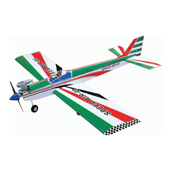
- Page 1 Instruction Manual book SPECIFICATION Wingspan : 1,500 mm 59 in. Length 1,160 mm 46 in. Weight 2.4 kg 5.28 Lbs. Radio 04 channels.
- Page 2 SPEED AIR-40. Instruction Manual. This instruction manual is designed to help you build a great flying aeroplane. Please read this manual thoroughly before starting assembly of your SPEED AIR-40. Use the parts listing below to identify all parts. WARNING. Please be aware that this aeroplane is not a toy and if assembled or used incorrectly it is capable of causing injury to people or property.
-
Page 3: Safety Precaution
SPEED AIR-40. Instruction Manual. SAFETY PRECAUTION. + This is not a toy + Be sure that no other flyers are using your radio frequency. + Wear safety glasses. + Keep loose clothing and wires away from the propeller. C/A glue. - Page 4 SPEED AIR-40. Instruction Manual. Remove covering. R e m o v e covering. Electric wire. Servo tray Servo mount. 3. Drill 1,5mm pilot holes through the block of wood for each of the four mounting screws provided with the servo. Install servo into ai- ...
- Page 5 SPEED AIR-40. Instruction Manual. 1. Using a ruler & pen to draw a straight line as below picture. 2. Locate nylon control horn, nylon con- trol horn backplates . Repeat the procedure for the other wing half. Mark line.
-
Page 6: Installing The Aileron Linkages
SPEED AIR-40. Instruction Manual. INSTALLING THE AILERON LINKAGES. Installing the aileron linkages as pictures below. Attach the clevis to the outer hole in the con- trol horn. Aileron pushrod. Bottom side. Repeat the procedure for the other wing half. WING ASSEMBLY. -
Page 7: Installing The Main Gear Wheels
SPEED AIR-40. Instruction Manual. 2)Test fit the dihedral brace into each wing half. The brace should slide in easily. If not, use 220 grit sandpaper with a sanding block and sand down the edges and ends of the brace until it fits properly. -
Page 8: Installing The Engine Mount
SPEED AIR-40. Instruction Manual. Repeat the procedure for the other main gear wheel. INSTALLING THE ENGINE MOUNT. 2mm. FUEL TANK. Secure. INSTALLING THE STOPPER ASSEMBLY 1) The stopper has been pre-assembled at the factory. - Page 9 SPEED AIR-40. Instruction Manual. 8) Feed three lines through the fuel tank com- partment and through the pre-drilled hole in the firewall. Pull the lines out from behind the en- gine, while guiding the fuel tank into place. Push the fuel tank as far forward as possible, the front of the tank should just about touch the back of the firewall.
-
Page 10: Nose Gear Installation
SPEED AIR-40. Instruction Manual. Installing steering arm as follow Steering arm. Adjust the nose gear steering arm until the arm is parallel with the fire wall. NOSE GEAR INSTALLATION. Steering arm. -
Page 11: Installing The Engine
SPEED AIR-40. Instruction Manual. INSTALLING THE ENGINE. Locate the long piece of wire used for the throttle pushrod. One end of the wire has been pre-bend in to a “Z” bend at the factory. This “Z” bend should be inserted into the throttle arm of the engine when the engine is fitted onto the engine mount. -
Page 12: Horizontal Stabilizer
SPEED AIR-40. Instruction Manual. HORIZONTAL STABILIZER. 1. Using a modeling knife, cut away the covering from the fuselage for the stabilizer and remove it. Remove covering. Bottom side ELEVATOR INSTALLATION. SERVO INSTALLATION. 1. Install the rubber grommets and brass collets into the elevator servo. - Page 13 SPEED AIR-40. Instruction Manual. The top of the stabilizer does not have the hinge pins exposed. C/A glue. 3. With the stabilizer held firmly in place, use a pen and draw lines onto the stabilizer where it and the fuselage sides meet. Do this on both the right and left sides and top and bottom of the stabilizer.
-
Page 14: Elevator Control Horn Installa- Tion
SPEED AIR-40. Instruction Manual. When cutting through the covering to re- ELEVATOR CONTROL HORN INSTALLA- move it, cut with only enough pressure to TION. only cut through the covering itself. Cut- ting into the balsa structure may weaken Elevator control horn install as same as the way of aileron control horn. - Page 15 SPEED AIR-40. Instruction Manual. Remove covering C/A glue. 2) Install control horn as same as picture below. C/A glue. Bottom.
-
Page 16: Vertical Stabilizer Installation
SPEED AIR-40. Instruction Manual. Elevator servo. Secure. VERTICAL STABILIZER INSTALLATION. Bend. Hinge. Cut. - Page 17 SPEED AIR-40. Instruction Manual. 1) Using a modeling knife, remove the covering from the top of the fuselage and the covering from over the precut hinge slot cut into the lower rear portion of the fuselage This C/A glue.
-
Page 18: Rudder Pushrod Installation
SPEED AIR-40. Instruction Manual. 4) Now, remove the vertical stabilizer and using a modeling knife, carefully cut just inside the marked lines and remove the film of the vertical stabilizer. Just as you did with the horizontal stabilizer, make sure you only press hard enough to cut the film, not the balsa vertical stabilizer. - Page 19 SPEED AIR-40. Instruction Manual. Nose gear pushrod. Receiver. SWITCH-THROTTLE SERVO INSTALLATION. Rudder servo. See pictures below. Servo tray. Elevator servo. INSTALLING THE RECEIVER AND BATTERY. 1) Plug the servo leads and the switch lead into the receiver. Plug the battery pack lead into the switch.
- Page 20 SPEED AIR-40. Instruction Manual. 2) Secure the switch in place using the two machine screws provided with the radio system. Switch. Secure servo tray on to the fuselage. Secure. ATTACHMENT WING-FUSELAGE. See pictures below: Thottl pushrod.
- Page 21 SPEED AIR-40. Instruction Manual. BALANCING. 1) It is critical that your airplane be bal- anced correctly. Improper balance will cause your plane to lose control and crash. Remove covering. THE CENTER OF GRAVITY IS LOCATED 95mm BACK FROM THE LEADING EDGE OF THE WING.
-
Page 22: Control Throws
SPEED AIR-40. Instruction Manual. CONTROL THROWS. 1) We highly recommend setting up a plane using the control throws listed. 2) The control throws should be measured at the widest point of each control surface.
Need help?
Do you have a question about the SPEED AIR-40 and is the answer not in the manual?
Questions and answers