Table of Contents
Advertisement
Quick Links
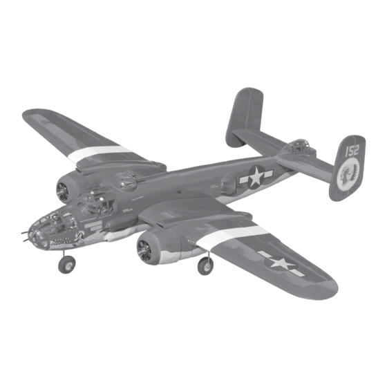
Instruction Manual book
SPECIFICATION
Wingspan :
Length
Weight
Radio
Servo
Parts listing required :
Electric Motor : ( 02pcs ) + AXI 2814/12.
Battery:
Speed control : ( 02pcs ) : 40 A
Engine (02PCS) :
Propeller :
1,590mm
:
1,230 mm
:
2.8 kg
:
06-7 channels.
:
08-10 servos.
+ KMS 2814/08
3 CELLS-LI-POLY
11.1V-4,500 mA.h-20 c .
25 -2 stroke.
9 x 6
62.60 in.
48.43 in.
6.16 Lbs.
Made in Vietnam.
ITEM CODE: BH51.
Advertisement
Table of Contents

Subscribe to Our Youtube Channel
Related Manuals for Black Horse Model B-25J Mitchell


Summary of Contents for Black Horse Model B-25J Mitchell
- Page 1 Instruction Manual book ITEM CODE: BH51. SPECIFICATION Wingspan : 1,590mm 62.60 in. Length 1,230 mm 48.43 in. Weight 2.8 kg 6.16 Lbs. Radio 06-7 channels. Servo 08-10 servos. Parts listing required : Electric Motor : ( 02pcs ) + AXI 2814/12. + KMS 2814/08 Battery: 3 CELLS-LI-POLY...
-
Page 2: Parts List
B-25J MITCHELL Instruction Manual This instruction manual is designed to help you build a great flying aeroplane. Please read this manual thoroughly before starting assembly of your B-25J MITCHELL. Use the parts listing below to identify all parts. WARNING. Please be aware that this aeroplane is not a toy and if assembled or used incorrectly it is capable of causing injury to people or property. -
Page 3: Safety Precaution
B-25J MITCHELL. INSTRUCTION MANUAL Caution: this model is not a toy! SAFETY PRECAUTION. If you are a beginner to this type of powered + This is not a toy model, please ask an experienced model flyer + Be sure that no other flyers are using your for help and support. - Page 4 B-25J MITCHELL Instruction Manual INSTALLING THE AILERON - FLAP SERVO CONTROL HORN. INSTALLING THE AILERON - SERVO CONTROL HORN. 1) Install the rubber grommets and brass eyelets onto the aileron servo. 2) Install the metal connector onto servo C/A glue.
- Page 5 B-25J MITCHELL. INSTRUCTION MANUAL Epoxy glue. 3) Install the aileron servo as same as picture. C/A glue Electric wire Thread Bottom side of leftwing. Remove covering Thread...
- Page 6 B-25J MITCHELL Instruction Manual Micro control connector. 4) Attach the micro control connector to the servo arms. Be sure to use the lock tie but it could free rotation. Remove the covering to pre-cut slot of aileron as picture below.
- Page 7 B-25J MITCHELL. INSTRUCTION MANUAL INSTALLING FLAP SERVO-CONTROL HORN. Remove the covering to pre-cut slot of flap as picture below. Aileron control horn Remove covering Flap Bottom side Secure Installing the flap servo as picture below . Secure Aileron...
- Page 8 B-25J MITCHELL Instruction Manual Insert flap control horn to the flap as picture below. C/A glue Secure CONTROL HORN OF THE FLAP Pushrod wire Flap control horn...
-
Page 9: Installing The Engine Mount
B-25J MITCHELL. INSTRUCTION MANUAL Repeat the procedure for the other wing half. 4.5mm INSTALLING THE ENGINE MOUNT. THERE ARE TWO OPTIONS: 1. ELECTRIC MOTOR. 3x 15mm. 2. ENGINE MOUNT. 1. ELECTRIC MOTOR. See pictures below... - Page 10 B-25J MITCHELL Instruction Manual...
- Page 11 B-25J MITCHELL. INSTRUCTION MANUAL C/A glue C/A glue C/A glue balsa wood piece Epoxy glue.
- Page 12 B-25J MITCHELL Instruction Manual INSTALLING RETRACTABLE LANDING GEAR 3 x 12mm 3 x 15mm Bottom side Top side Mark point Drill 2mm hole...
- Page 13 B-25J MITCHELL. INSTRUCTION MANUAL Secure 3 x 12mm...
- Page 14 B-25J MITCHELL Instruction Manual Retract landing Mark point gear pushrod Secure Top side...
- Page 15 B-25J MITCHELL. INSTRUCTION MANUAL Top side Mark point Bottom side of left haft wing Top side of left haft wing Top side of left haft wing...
- Page 16 B-25J MITCHELL Instruction Manual Bottom side ENGINE COWLING INTALLATION. Install the engine cowl as same as picture below. Cowling Bottom nacelle Ply wood piece Center line Ply wood piece 3 x 12 mm Secure the wing to the bottom nacelle...
- Page 17 B-25J MITCHELL. INSTRUCTION MANUAL Left nacelle Right nacelle Mark line 1 Top side Cut nacelle as picture below . Mark line 2...
- Page 18 B-25J MITCHELL Instruction Manual C/A glue Line 2 Line 1 C/A glue Mark line 3 Mark line 4 Line 4 Line 3...
- Page 19 B-25J MITCHELL. INSTRUCTION MANUAL Drill 4mm a hole diameter C/A glue Line 1 Line 2 Line 3 Line 4 Mark point Secure Repeat procedure for the other wing panel.
- Page 20 B-25J MITCHELL Instruction Manual Secure OPTION 2: ENGINE MOUNT. Secure...
- Page 21 B-25J MITCHELL. INSTRUCTION MANUAL C/A glue balsa wood piece Epoxy glue Mark point...
- Page 22 B-25J MITCHELL Instruction Manual 3x20mm 3x20mm Secure Tie wrap. FUEL TANK. Vent tube Fuel pick - up tube Fuel fill tube...
- Page 23 B-25J MITCHELL. INSTRUCTION MANUAL Drill 2mm hole Tie wrap. Throttle pushrod 92mm Mark point Secure...
- Page 24 B-25J MITCHELL Instruction Manual Secure Throttle servo Throttle pushrod...
- Page 25 B-25J MITCHELL. INSTRUCTION MANUAL Trim and cut Bottom side Repeat the procedure for the other wing half.
- Page 26 B-25J MITCHELL Instruction Manual INSTALLING RETRACT NOSE GEAR. 3 x 12mm Secure Secure Secure...
- Page 27 B-25J MITCHELL. INSTRUCTION MANUAL Epoxy glue C/A glue C/A glue...
-
Page 28: Servo Installation
B-25J MITCHELL Instruction Manual Nose gear servo Secure SERVO INSTALLATION. 1) Install the rubber grommets and brass eyelets onto the elevator servo and nose gear servo. 2) Install the metal connector onto servo arm. Servo for retract only RETRACTABLE INSTALLATION... - Page 29 B-25J MITCHELL. INSTRUCTION MANUAL Metal conector Servo arm Retracts of retracts. pushrod system 25mm...
- Page 30 B-25J MITCHELL Instruction Manual...
-
Page 31: Horizontal Vertical Stabilizer In- Stallation
B-25J MITCHELL. INSTRUCTION MANUAL HORIZONTAL VERTICAL STABILIZER IN- STALLATION. C/A glue VERTICAL INSTALLATION. C/A glue Elevator servo Elevator pushrod Bottom Remove covering C/A glue... - Page 32 B-25J MITCHELL Instruction Manual Remove covering...
- Page 33 B-25J MITCHELL. INSTRUCTION MANUAL Secure C/A glue Mark point A hole 2.5mm diameter.
- Page 34 B-25J MITCHELL Instruction Manual C/A glue Mark point Remove covering...
- Page 35 B-25J MITCHELL. INSTRUCTION MANUAL C/A glue Epoxy glue Bottom 90 - degree C/A glue C/A glue...
- Page 36 B-25J MITCHELL Instruction Manual C/A glue C/A glue...
-
Page 37: Horizontal Installation
B-25J MITCHELL. INSTRUCTION MANUAL Secure HORIZONTAL INSTALLATION. - Page 38 B-25J MITCHELL Instruction Manual Vertical Stabilizer. Horizontal 90º Stabilizer. Install the elevator pushrod- elevator control horn as picture below.
- Page 39 B-25J MITCHELL. INSTRUCTION MANUAL Elevator servo. Elevator pusrod Secure Elevator control horn . Elevator Elevator control horn control horn...
- Page 40 B-25J MITCHELL Instruction Manual Secure ATTACHMENT WING-FUSELAGE. See pictures below: Secure...
-
Page 41: Installing The Receiver And Battery
B-25J MITCHELL. INSTRUCTION MANUAL Tie wrap. INSTALLING THE RECEIVER AND BATTERY. See picture below. Battery battery Nose gear servo... - Page 42 B-25J MITCHELL Instruction Manual Radiator.
- Page 43 B-25J MITCHELL. INSTRUCTION MANUAL C/A glue...
- Page 44 B-25J MITCHELL Instruction Manual...
- Page 45 B-25J MITCHELL. INSTRUCTION MANUAL...
- Page 46 B-25J MITCHELL Instruction Manual BALANCING. 1) It is critical that your airplane be bal- anced correctly. Improper balance will cause your plane to lose control and crash. THE CENTER OF GRA VITY IS LOCA TED 95MM BACK FROM THE LEADING EDGE OF THE WING.
-
Page 47: Control Throws
B-25J MITCHELL. INSTRUCTION MANUAL CONTROL THROWS. 1) We highly recommend setting up a plane using the control throws listed. 2) The control throws should be meas- ured at the widest point of each control sur- face. 3) Check to be sure the control surfaces move in the correct directions.
Need help?
Do you have a question about the B-25J Mitchell and is the answer not in the manual?
Questions and answers