Table of Contents
Advertisement
Quick Links
Advertisement
Table of Contents

Related Manuals for Black Horse Model Travel Air


Summary of Contents for Black Horse Model Travel Air
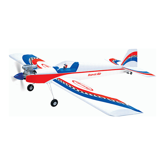
- Page 1 Instruction Manual book SPECIFICATION Wingspan : 1,550 mm 61.02 in. Length 1,250 mm 49.2 in. Weight 2.4 kg 5.28 Lbs. Radio 04 channels.
-
Page 2: Parts List
Instruction Manual Item code:BH06. This instruction manual is designed to help you build a great flying aeroplane. Please read this manual thoroughly before starting assembly of your TRAVEL AIR. Use the parts listing below to identify all parts. WARNING. Please be aware that this aeroplane is not a toy and if assembled or used incorrectly it is capable of causing injury to people or property. -
Page 3: Safety Precaution
TRAVEL AIR- Instruction Manual Item code:BH06. Caution: this model is not a toy! Caution! do not heat the film more than is If you are a beginner to this type of powered absolutely necessary. If the air or the iron is... -
Page 4: Installing The Aileron Servos
TRAVEL AIR- Instruction Manual Item code:BH06. REPLACEMENT SMALL PARTS 5x35mm. 3x12mm. 3x12mm. 1. Aluminium landing gear. 2. Fuel Tank. 3. Wheels. 4.Tie wrap Top side. 5. Plastic parts for elevator and rudder pushrod. 6. Tail gear 7. Spinner. Bottom side. - Page 5 TRAVEL AIR- Instruction Manual Item code:BH06. Cut the covering away from the slot. Temporary pin to 3. Drill 1,5mm pilot holes through the block keep hinge centered. of wood for each of the four mounting screws provided with the servo. Install servo into ai- leron servo tray as same as picture below.
- Page 6 TRAVEL AIR- Instruction Manual Item code:BH06. INSTALLING THE AILERON CONTROL HORN. Install aileron control horn as same as picture below . Electric wire. 2 x20mm. Control horn of Aileron 5. Instal servo tray with aileron servo into the wing as same as picture below.
-
Page 7: Installing The Aileron Linkages
TRAVEL AIR- Instruction Manual Item code:BH06. 3. Plug the aileron servo into the receiver and center the servo. Install the servo arm onto the servo. The servo arm should be perpen- dicular to the servo and point toward the mid- dle of the wing. -
Page 8: Installing The Engine Mount
TRAVEL AIR- Instruction Manual Item code:BH06. INSTALLING THE ENGINE MOUNT. Drill a hole 2.5mm diameter. INSTALLING THE ENGINE. Locate the long piece of wire used for the throttle pushrod. One end of the wire has been pre-bend in to a “Z” bend at the factory . This “Z”... -
Page 9: Installing The Stopper Assembly
TRAVEL AIR- Instruction Manual Item code:BH06. When the stopper assembly is installed in the tank, the top of the vent tube should rest just below the top surface of the tank. It should not touch the top of the tank. -
Page 10: Installing The Throttle Servo
TRAVEL AIR- Instruction Manual Item code:BH06. 8. Feed three lines through the fuel tank compartment and through the pre-drilled hole in the firewall. Pull the lines out from behind the engine, while guiding the fuel tank into place. Push the fuel tank as far forward as possible, the front of the tank should just about touch the back of the firewall. -
Page 11: Installing The Spinner
TRAVEL AIR- Instruction Manual Item code:BH06. After installing the adjustable metal con- Throttle wire. nector apply a small drop of thin C/A to the bottom nut. This will prevent the con- nector from loosening during flight. Throttle servo INSTALLING THE SPINNER. -
Page 12: Elevator Installation
TRAVEL AIR- Instruction Manual Item code:BH06. HORIZONTAL STABILIZER INSTALLATION. See pictures below: Secure. ELEVATOR INSTALLATION. SERVO INSTALLATION. 1. Install the rubber grommets and brass collets into the elevator servo. Test fit the servo into the servo tray. Cut the covering 2. - Page 13 TRAVEL AIR- Instruction Manual Item code:BH06. 2. Draw a center line onto the horizontal 4. Remove the stabilizer. Using the lines you just drew as a guide, carefully remove the stabilizer. Then slide the horizont al into the covering from between them using a modeling fuselage.
-
Page 14: Elevator Control Horn Installa- Tion
TRAVEL AIR- Instruction Manual Item code:BH06. Top side Epoxy glue Bottom side. Check to mark sure the wing and stabi- lizer are paralell. If they are not, lightly sand ELEVATOR CONTROL HORN INSTALLA- the opening in the fuselage for the stabilizer TION. -
Page 15: Elevator Pushrod Installation
TRAVEL AIR- Instruction Manual Item code:BH06. Drill 1 hole with 1.5mm diameter. Elevator pushrod. Elevator servo. Secure. Cut. ELEVATOR PUSHROD INSTALLATION. Elevator pushrod install as same as the way of aileron pushrod. Please see pictures be- low. Bend and... -
Page 16: Vertical Installation
TRAVEL AIR- Instruction Manual Item code:BH06. VERTICAL INSTALLATION. See picture below: Elevator pushrod. Control clasp. Hinge. Cut the covering RUDDER SERVO INSTALLATION. away from the slot. Rudder servo install as same as method of elevator servo. See picture below: Temporary pin to keep hinge centered. - Page 17 TRAVEL AIR- Instruction Manual Item code:BH06. 2. Slide the rudder into the fuselage as 1) Using a modeling knife, remove the same as picture below. covering from the top of the fuselage and the covering from over the precut hinge slot cut into the lower rear portion of the fuselage This slot accepts the lower vertical.
- Page 18 TRAVEL AIR- Instruction Manual Item code:BH06. Epoxy glue. Remove covering. Top side 5. Put the vertical stabilizer back in place. Using a triangle, check to ensure that the vertical stabilizer is aligned 90 de- gree to the horizontal stabilizer.
- Page 19 TRAVEL AIR- Instruction Manual Item code:BH06. Elevator pushrod. Rudder control horn. Drill a hole 1.5mm. Rudder pushrod. Secure. Snap keeper Rudder pushrod.
-
Page 20: Mounting The Tail Wheel Bracket
TRAVEL AIR- Instruction Manual Item code:BH06. MOUNTING THE TAIL WHEEL BRACKET. 3x12mm. 2. Using a pen, mark the locations of the 1. Set the tail wheel assembly in place two mounting screws. Remove the tail wheel on the plywood plate. - Page 21 TRAVEL AIR- Instruction Manual Item code:BH06. MAIN GEAR INSTALATION. PARTS REQUIRED Cut. 5x35mm 1) Assemble and mounting the wheel p ants as shown in the following pictures. C/A glue 2) Using the hardware provided, mount the main landing gear to the fuselage.
-
Page 22: Installing The Switch
TRAVEL AIR- Instruction Manual Item code:BH06. Bottom side INSTALLING THE SWITCH. 1. Cut out the switch hole using a modeling knife. Use a 2mm drill bit and drill out the two mounting holes through the fuselage side. -
Page 23: Wing Attachment
TRAVEL AIR- Instruction Manual Item code:BH06. 3. Position the battery pack and receiver 2. Attach the aluminium tube into the behind the fuel tank. Use sing to two tie wraps fuselage. to hold the battery and receiver securely in place as picture below. - Page 24 TRAVEL AIR- Instruction Manual Item code:BH06. 3.Insert two wing panels as pictures be- top side low. Insert and secure BALANCING. 1) It is critical that your airplane be bal- anced correctly. Improper balance will cause your plane to lose control and crash.
-
Page 25: Pre-Flight Check
TRAVEL AIR- Instruction Manual Item code:BH06. PRE-FLIGHT CHECK. 1. Completely charge your transmitter and receiver batteries before your first day of fly- ing. 2. Check every bolt and every glue joint in ...
Need help?
Do you have a question about the Travel Air and is the answer not in the manual?
Questions and answers