
Related Manuals for AES 605


Summary of Contents for AES 605
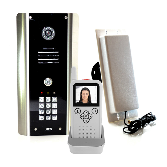
- Page 1 Installation & User Manual 6 0 5 D E C T + 2 . 4 G I n t e r c o m W ireless Video Inter com System Models 605AB, 605ABK P a g e...
-
Page 2: Table Of Contents
Contents …………….Pg 3 Overview of system …………….Pg 3 Site Survey …………….Pg 3 Mounting the Transmitter …………….Pg 3 Power supply …………….Pg 4 Mounting Architectural Panels …………….Pg 4 Mounting Hooded Panels …………….Pg 4 Mounting Flush Panels …………….Pg 5 Wiring …………….Pg 5 Code Lock Keypad Connections …………….Pg 6 Wiring Tips …………….Pg 6... -
Page 3: Overview Of System
Overview of System Please read this entire manual before attempting to install this system. This system should only be installed by a professional automatic gate installer or access control specialist installer. It is recommended that the system be range tested on site BEFORE being fully installed. Site Survey Before installing this system, you need to be sure that the range of the system will be sufficient. -
Page 4: Power Supply
Mounting the Antenna Mount the antenna as high as possible to achieve longest range. TIP: Antenna beam width is approximately 40 degrees. For short range door intercoms, ask your distributor or dealer for an omni-pole type antenna with 360 degree beam angle. -
Page 5: Wiring
Wiring Tamper Sense OUT2 Relay (-)GND Select DU out K or A OUT3 OUT1 OUT2 Wiring Tips Note: The manufacturer can only support the use, operation and functionality of the intercom and keypad themselves. Professional wiring to door release or automatic gate P a g e... -
Page 6: Keypad Overview
systems is the responsibility of the installer. Please consult a security integrator for further support. Advanced Keypad Connections Advanced connections INT Lock – Used to operate a door in conjunction with Tamper INT Lock another keypad. 24v dc max voltage, 100mA sink. O/P1 inhib O/P1 inhib –... -
Page 7: Basic Keypad Programming
Basic Keypad Programming Quick start guide Tip: The engineer code 1) Enter programming mode (amber LED should be ON) must be the same length as user codes. So if using a 6 digit engineers code, then 2) Enter a new user code... user codes must also be 6 digits long etc. - Page 8 0 = start / stop toggle mode (latching) 51=relay1 Validate 1-99999 = seconds momentary operation 52=relay2 53=relay3 Delete a user code even if you don’t know the code… 10=relay1 Delete code ID location to be deleted Validate 20=relay2 30=relay3 Delete an entire group of codes 10=relay1 group Super delete code Validate...
-
Page 9: Using The Keypad
Using the keypad Using the standard codes… Once you have exited out of programming mode, simply enter the user code. Using super user codes Activate output 1 Activate output 2 Activate output 3 The Video Handset The handset should be charged for 8 hours before use. It is recommended to give it at least 1 hour charge before range testing. -
Page 10: The Handset
Answering Calls 1. When the intercom calls, identify the visitor on the screen. 2. Press the OK button to answer the call. 3. Speak clearly into the top of the handset at a distance of 10-20cm. 4. During the call press < or > to increase or decrease volume. 5. - Page 11 Settings The following settings can be changed in the system. To make any of the following settings, put the system into monitoring mode by pressing and holding the key for a few seconds. 1. Brightness – Adjusts screen brightness. 2. Language – Select English, French or German. 3.
- Page 12 Using the Audio Handset 12.21 Menu Open door / gate Answer / end call Change ring tone Up and down arrows increase / decrease ring Select or enter and speech volume Menu Button Press and hold the menu button for 3 seconds and the display will show “ti” Use the up and down arrows you can select the relay Latch time 1- 9 seconds Press “OK”...
-
Page 13: Testing
Testing 1. Press the call button on the intercom and all coded handsets should ring (max 4 handsets). 2. Answer the call on any handset and adjust speech volume while on the call as per instructions. 3. Activate the door or gate release and check the relay activates. Adjusting time on Audio Handset Press MENU for more than 2 seconds, and then use up and down arrow keys to set hour. -
Page 14: Troubleshooting Guide
Troubleshooting guide Q. The unit will not ring the handset. A. Try re-coding the handset and transmitter as per instructions. - Check push button wiring to the transmitter with multi-meter. -Check power cable distance from power adaptor to transmitter is less than 4 metres. Q. - Page 15 A. This can be caused by the inbuilt surge protection being short circuited due to a surge, over voltage, or wiring fault. Disconnect all wiring, check, and re-wire again. If the fault still appears, contact your dealer for service. P a g e | 15...
- Page 16 P a g e | 16...
- Page 17 P a g e | 17...
Need help?
Do you have a question about the 605 and is the answer not in the manual?
Questions and answers