
Subscribe to Our Youtube Channel
Related Manuals for AES CellCOM Plus AB


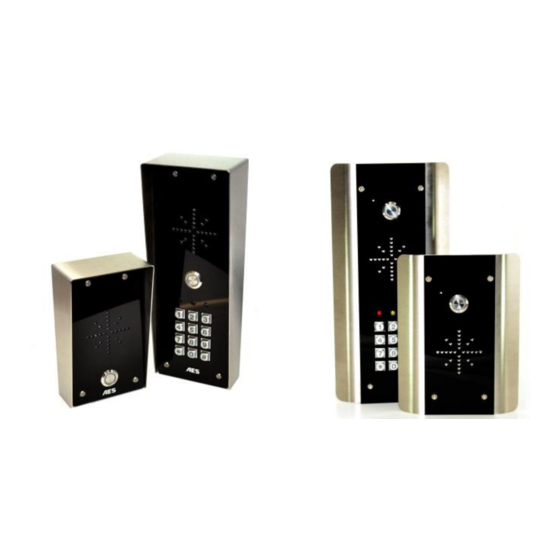
Summary of Contents for AES CellCOM Plus AB
- Page 1 Installation & User Manual C e l l C O M GSM Intercom System Models AB, ABK, HB, HBK, FB, FBK Version 1 P a g e...
-
Page 2: Table Of Contents
Contents …………….Pg 3 Overview of system …………….Pg 3 Site Survey …………….Pg 3 SIM card …………….Pg 3 Power …………….Pg 4 Installation …………….Pg 4 Architectural panels …………….Pg 4 Hooded Panels …………….Pg 4 Flush Panels …………….Pg 5 Installing the SIM card …………….Pg 5 Connections on GSM controller …………….Pg 6 Codelock Keypad connections... -
Page 3: Overview Of System
Overview of System Please read this entire manual before attempting to install this system. This system should only be installed by a professional automatic gate installer or access control specialist dealer. It is recommended that the system be set up, configured, commissioned and tested on a workshop bench before taken to site for installation. -
Page 4: Installation
Installation Do not remove the protective film until the system is Speech fully installed and working. Protective coverings are Unit there to protect the intercom from scratches and 200mm marks during installation. Antenna height is best higher than intercom for cleaner audio and also better reception. -
Page 5: Installing The Sim Card
Inserting the SIM card Note: This unit is a 2G quad band system, operating on standard 2G network frequencies of 850/900/1800/1900MHz. Please ensure the SIM card is a 2G compatible SIM card. The SIM may also close be 3G and 4G capable as well, as long as both the SIM and the network also support 2G. -
Page 6: Codelock Keypad Connections
Code Lock Keypad connections (Keypad versions only) Tamper Commonly used connections INT Lock O/P1 inhib Outputs – This keypad has 3 outputs. All can be Sense (-)GND programmed for momentary and latching operation. DU out For gate systems and AC strike locks, connect a K or A keypad relay (normally open) in parallel with the GSM OUT3... -
Page 7: Output Connections Example
Output Connections Example Gate motor controller modem close Other exit Out 1 device, e.g. keypad Out 2 Magnetic Lock 12v dc Other exit 12v dc device, e.g. Separate keypad This example shows relay 1 connected to a gate motor controller for vehicle gates, and output 2 connected to a magnetic lock for a door or pedestrian gate. -
Page 8: Powering Up
Powering Up Perform a final check of wiring and ensure the antenna is connected before switching on the power. Once the power is switched on, the power LED should illuminate. TIPS: My GSM LED is still searching… Power LED -Check the SIM card is registered and can make a CPU LED call in a phone. - Page 9 Step 2: Programming dial out numbers for single call button models Programing text messages must start with a pass code string, followed by a command, followed by data, and each command is separated in the SMS by #. To begin, program the unit to dial numbers when the call button is pressed. This module will dial up to 4 telephone numbers in sequence, for each push button.
- Page 10 141 = button 4, tel no 1. 142 = button 4, tel no 2. 143 = button 4, tel no 3. 181 = button 4, tel no 1. 144 = button 4, tel no 4. 182 = button 4, tel no 2. 183 = button 4, tel no 3.
-
Page 11: Complete List Of Parameters
GSM unit complete list of parameters The table below show the complete list of features in the cellular part of the intercom. Programming messages below must begin with 9999# (assuming 9999 is still the programming passcode)… Changing pass codes 01????# Change programming password 9999 Change access control password (SMS control of relays, or non-... -
Page 12: Keypad Overview
Notification Number Store a master user, who will receive a SMS notification from the 78number# intercom each time any of the output relays are triggered. Where “text” is the content of the message to be sent. E.g. “Gates Opened, or Door Opened”. This will be sent on closing of 79text# any output relay. -
Page 13: Basic Keypad Programming
Basic Keypad Programming Quick start guide Tip: The engineer code 1) Enter programming mode (amber LED should be ON) must be the same length as user codes. So if using a 6 digit engineers code, then 2) Enter a new user code... user codes must also be 6 digits long etc. - Page 14 Example: Add user 31 to have access code 5555 operating relay 2…. Group 2 Add code Location 31 Pin code 5555 Validate Programming relay output times and modes… 0 = start / stop toggle mode (latching) 51=relay1 Validate 1-99999 = seconds momentary operation 52=relay2 53=relay3 Delete a user code even if you don’t know the code…...
-
Page 15: Using The Keypad
Using the keypad Using the standard codes… Once you have exited out of programming mode, simply enter the user code. Using super user codes Activate output 1 Activate output 2 Activate output 3 Using the intercom This cellular intercom can dial up to 4 numbers in sequence for any call button when pressed.. Dialling….. -
Page 16: Check If Door/Gate Opened/Closed
Check if door or gate is open or closed Send the SMS as shown, and the unit will reply showing the status *22# of the input limit switch (if used), and the relay.. This example shows that the input sensor is in OPEN state. Relay 1 OPEN, is OFF and Relay 2 is latched ON. -
Page 17: Maintenance Of Intercom
Maintenance of the Intercom The intercom SIM card will need topped up occasionally if it is a pre-pay casual SIM card. It is recommended that you register this SIM card on the provider’s web site. You can register card payment details. Many networks offer an auto top up feature, which means they will automatically top up your intercom when the balance runs low. - Page 18 -Change SIM card if necessary to another network which may have better coverage. -Purchase a high gain antenna. -Increase height of antenna. This may also be caused by a defective microphone, water on a microphone from a sprinkler for example, or dirt blocking the microphone hole. If reception is optimum and the problem persists, contact your supplier or installer.
- Page 19 P a g e | 19...
- Page 20 P a g e | 20...
Need help?
Do you have a question about the CellCOM Plus AB and is the answer not in the manual?
Questions and answers