Table of Contents

Related Manuals for Leica IP C


Summary of Contents for Leica IP C
- Page 1 Instructions for use Leica IP C - Automated printing system for tissue cassettes Leica IP C, V 1.9, English – 03/2017 Order No.: 14 0602 80101, RevH Always keep this manual with the instrument. Read carefully before working with the instrument.
- Page 3 Leica reserves the right to change technical following thorough investigation in this field. specifications as well as manufacturing process- We are under no obligation to update the pres- es without prior notice.
-
Page 4: Table Of Contents
Table of contents Important Information ....................... 6 Symbols in the text and their meanings..................6 1.1.1 Symbols on the transport packaging and their meanings ............. 7 Qualification of personnel ......................8 Intended use of instrument ......................8 Instrument type ..........................8 Safety ............................ - Page 5 Troubleshooting ........................60 Malfunctions ..........................60 Status messages ......................... 61 Error messages ........................... 62 Changing the flash bulb ......................65 Power failure ..........................65 Replacing the secondary fuses ....................66 Warranty and Service ......................67 Decontamination Certificate ....................68 Leica IP C...
-
Page 6: Important Information
Important Information 1.1 Symbols in the text and their meanings Symbol for labeling electrical and elec- tronic equipment in accordance with Section 7 of the German Electrical and Warnings Electronic Equipment Act (ElektroG). Ele- appear in a gray box and are marked by a warning triangle ktroG is the law regarding the sale, re- turn and environmentally sound disposal... -
Page 7: Symbols On The Transport Packaging And Their Meanings
With a pitch of 60° or more, the blue quartz sand flows into the arrow-shaped indicator window and sticks there permanently. Improper handling of the shipment is immediately detectable and can be proven definitively. Leica IP C... -
Page 8: Qualification Of Personnel
1.3 Intended use of instrument Leica IP C printer system for standard histology cassettes. • The instrument has been designed for use in pathology, histology, cytology, toxicology and similar laboratories, and there only for printing tissue cassettes. -
Page 9: Safety
Malfunctions that impede safety must be remedied immediately. For current information about applicable guidelines, please refer to the CE declaration of conformity and on our Internet site at: http://www.LeicaBiosystems.com Leica IP C... -
Page 10: Warnings
Safety 2.2 Warnings The safety devices installed in this instrument by the manufacturer only constitute the basis for accident prevention. Operating the instrument safely is, above all, the responsibility of the owner, as well as the designated personnel who operate, service or repair the instrument. To ensure trouble-free operation of the instrument, make sure to comply with the following instructions and warnings. - Page 11 The painted surfaces and the control panel of the instrument are not resistant to xylene or acetone! • While working and during cleaning, no liquid may get into the interior of the instrument. Leica IP C...
-
Page 12: Instrument Components And Specifications
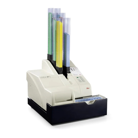
Instrument Components and Specifications 3.1 Overview—instrument 1 - Basic instrument 2 - Cassette magazines - Magazine no. 1 3 - Control panel 4 - Lid 5 - Cover—cartridge slot 6 - Unload station (manual) Fig. 2 Instructions for Use V 1.9 RevH – 03/2017... - Page 13 Prior to operation, the cleaning car- tridge must be exchanged for an - Location plate ink cartridge - See "Exchanging the - External alarm jack cartridge". - Socket for printer cable Leica IP C...
-
Page 14: Technical Data
Instrument Components and Specifications 3.2 Technical data General Approvals: The instrument-specific approval marks are located at the rear panel of the instrument, next to the name plate. Nominal supply voltages: 100 to 120 V ~ +/- 10 % 200 to 240 V ~ +/- 10 % Nominal frequency: 50 to 60 Hz Power fuse:... - Page 15 Windows VISTA, Windows 7 (32 bit and 64 bit) ) Average value—exact speed in each individual case depending on system configuration and software used. ) Average values are given; the exact number depends on the print density. ) Measured in addressable dots per inch Leica IP C...
-
Page 16: Print Specifications
Leica IP C. Fig. 5 3.3.1 Requirements for cassettes A wide variety of standard cassettes may be used in the IP C; however, the following restric- tions must be observed: • Suitable for printing are all standard cassettes without lids, of the following dimensions: Length without lid x Width = max. 41.3 x 28.9 mm... - Page 17 If the slides/cassettes you are currently using are not listed above, please contact your local Leica Microsystems’ representative. The following cassettes have been successfully tested with the Leica IP C. Cassette type Imprinting in Leica IP C...
-
Page 18: Print Specifications
Instrument Components and Specifications 3.3.2 Print specifications Print resolution The print head of the instrument has a preset resolution of 360 dpi in both directions (vertical and horizontal). Each printed line has a maximum height of 128 dots. This corresponds to a value of 9.03 mm. In horizontal direction, the printable surface is Fig. -
Page 19: Printing Bar Code
Data should never be printed as bar code only, but also as text (line of optical characters above or below the bar code), to ensure that no information is lost for the above reasons. Leica IP C... - Page 20 • Barcode style (2D). • The number and types of characters required in the barcode. • The quality and resolution capabilities of the bar code reader As always, using Leica recommended print media will produce the highest quality print. However, it is highly recommended that any bar code solution be tested prior to implementation. Please check with your local represen- tative for details on achieving the maximum number of characters with 2 D bar codes.
-
Page 21: Resistance Against Reagents
A wide range of factors beyond Leica's control can have negative effects on the results. The test conditions stated below can therefore only serve as an outline for individual labora- tory test specifications. -
Page 22: Instrument Setup
If the tip of the arrow is blue, the shipment was not handled as pre- scribed. In this case, please mark the shipping documents accord- ingly and check the shipment for damage! Fig. 11 Fig. 12 Leica IP C... - Page 23 Fig. 15 • When the instrument has been set up at its final area of use, remove the blue foam transport anchor (6 – Fig. 15, pull upwards). Fig. 13 Leica IP C...
-
Page 24: Installing The Printer
Instrument Setup 4.2.1 Installing the printer When unpacking the printer, at least two people (one person on each side of the printer) are required to lift the printer out of the box and place it onto the laboratory bench. • Check the instrument for transport damage. • Check all accessories delivered against your order to make sure there are no discrepancies. -
Page 25: Standard Delivery
Instrument Setup 4.3 Standard delivery The Leica IP C standard equipment consists of the following items: 1 Leica IP C, basic instrument without unload station 14 0602 33206 1 Cleaning cartridge (in the instrument) 14 0601 42865 1 UV ink cartridge Leica... -
Page 26: Installing The Manual Unload Station
Instrument Setup 4.4 Installing the manual unload station The unload station supplied consists of: 28 - Unload station 29 - Screening plate 30 - Collar screws (3 pcs.) 31 - Slotted screws with washers (2 pcs.) Install as follows (Fig. 17): • Open lid (4). -
Page 27: Automated Unload Station (Optional)
• Place the stack of trays (39) onto the lifting table (38) of the automated unload station. chapter 5.2 for details on the lifting table controls. Fig. 18 Leica IP C... -
Page 28: Installing/Exchanging The Flash Bulb
Instrument Setup 4.6 Installing/exchanging the flash bulb Removing the old flash bulb Switch the instrument off and unplug it from power supply. Allow the flash bulb to cool off before removing it. Do not handle the flash bulb with bare hands. - Page 29 • The contact spring (44) has to touch the igni- tion wire (45) of the bulb after being inserted. • Swing the reflector downwards. Reinsert and retighten screw (49). • Close lid (4) of the instrument again. Fig. 26 Leica IP C...
-
Page 30: Filling And Inserting The Magazines
Instrument Setup 4.7 Filling and inserting the magazines Inserting the strips Depending on the type of cassette used, addi- tional inserts must be placed into the magazine (54) to guide the cassettes properly: This includes: 53 – Metal insert 50 – Adhesive strip (2 mm thick) Metal strip Insert the metal strip (53) so that the angled part (58) touches the back panel (56) of the magazine... - Page 31 Printer that they are aligned properly and that there are no gaps between the cassettes. • To achieve this, use your finger to carefully lift the cassettes slightly from below, then release them—they should then lie in the magazine properly (see Fig. 32). Fig. 31 Leica IP C...
- Page 32 Leica IP C. ified in the table on page 31 are to be Leica does not guarantee that cassette used, use trial and error to find out types other than those tested can be which insert is required in the maga- processed in the instrument.
-
Page 33: Electrical Connection
3.5 mm-diameter jack connector printer port (optional accessory). (60). • For details about the remote alarm see chapter 5.3. Fig. 35 • Connect the cable to one of the serial ports (COM 1, COM 2) of the computer containing the control software. Leica IP C... -
Page 34: Exchanging The Cartridge
Instrument Setup 4.9 Exchanging the cartridge The printer is supplied with a cleaning cartridge (64) inserted. To be able to print, the cleaning cartridge must be exchanged for an ink cartridge. To do so, proceed as follows: • Open the cover plate (5) on the left side of the instrument (pressing its top left corner). - Page 35 • Store the removed cleaning cartridge in a sealed container. The cartridge is full and can be used twice more to clean the print head. The expiration date can be found on the red label. Fig. 41 Leica IP C...
- Page 36 Instrument Setup • Remove the ink cartridge (66) from the delivery Exchanging the cartridge (continued) carton and shake it a few times, then remove the protective foil. • The ink cartridge must be replaced after 60,000 printouts or 3.5 months. The instrument setup date can be recorded on the white sur- face (65) on the front (Fig.
- Page 37 1. • Press and hold the CLEAN button until "00" is displayed, then release the button. A cassette is imprinted with a stored test image. If the print result is not satisfactory, this step can be repeated several times. Leica IP C...
-
Page 38: Installing The Printer Driver
Instrument Setup 4.10 Installing the printer driver This printer driver only runs under the operating systems Microsoft Windows NT 4.0, Windows 2000 and Windows XP. The description below refers to the installation of the driver under Windows NT. Any steps that need to be carried out in a different way when installing under other Windows versions are also explained below. - Page 39 Instrument Setup 6. In the selection window, select PRINTER IP C (blue mark). If no (or other) selectable options are displayed, click on "HAVE DISK..." to return to the previous dialog box and repeat insertion of the path. 7. If the message shown on the left is displayed, the driver has already been installed on your PC on a previous occasion (e.g.
- Page 40 Instrument Setup Configuring the serial port: 1. Open the printer folder: START --> SETTINGS --> PRINTERS 2. Right-click on the icon of the newly installed printer, a quick menu opens up. Click on PROPERTIES..3. The PROPERTIES window contains several tabs; select the PORTS tab. Caution! Windows 2000 and XP do not contain the PORTS page.
-
Page 41: Operation
Ink cartridge will be empty shortly—keep the printer that the magazine has replacement ink cartridge handy. been refilled. The printer will resume the interrupted print job LED illuminates: where previously left off. Ink cartridge empty, no further printing possible. Leica IP C... - Page 42 Operation POWER POWER Switching from POWER ON to STANDBY mode and back LED illuminated – POWER ON mode • Power is supplied to all printer systems. • The flash power supply is continuously being recharged. • The printer is ready to print immediately. LED flashes – STANDBY mode • All power absorbers of the printer are switched off, with the exception of those related directly to the processor (power saving mode). • The printer cleans a print head at regular intervals (e.g. 4 times a day).
- Page 43 If several errors occur simultaneously, the highest priority error code is displayed first. After that error has been acknowledged by pressing ERROR, the second highest priority error code is displayed and so on. Leica IP C...
- Page 44 Operation CLEAN Cleaning the print head and carrying out a print test Pressing CLEAN briefly While a print job is in progress: • The print job is interrupted. "00" will appear on the display for about 2 s. • A print head clean is carried out and subsequently the print job is re- sumed. If no print job is in progress: • The print head is cleaned immediately after "00"...
- Page 45 Be careful about getting near the sen- sor (66). Any object getting closer than 2 mm to the sensor will trigger a lifting movement. Fig. 49 Leica IP C...
-
Page 46: Display Indications
Operation 5.2 Display indications Display indication Magazine empty (in combination with "Mag. Empty" LED) 1 - Magazine No. 1 empty Magazine No. 4 empty 2 - Magazine No. 2 empty Magazine No. 5 empty 3 - Magazine No. 3 empty Magazine No. - Page 47 The display consists of two parts: The "8" is a warning that a magazine ejector is mechanically blocked. The second digit of the message specifies the number of the affected magazine. Error messages All displayed numbers between 20 and 78 and 89 and 93. Leica IP C...
-
Page 48: Alarm Functions
100 mA. A maximum voltage of 24 V DC must not be ex- ceeded. For details on how to connect a remote alarm device to the Leica Printer, please contact your local Leica sales office or the man- ufacturer directly. -
Page 49: Printer Driver Settings
Operation 5.4 Printer driver settings With the Leica IP C cassette printer you can print cassettes from any Windows application al- lowing the user to individually configure the printing parameters. The description below refers to Microsoft Wordpad, a program that is part of any Windows installation and therefore avail- able on all PCs supported by the printer driver. - Page 50 Operation Selectable options in the PAPER --> SOURCE dialog box When clicking on the Source input field, an al- phabetical list of all cassette supply options from all 6 magazines opens up. • MANUAL FEED means, that individual cas- settes will be placed onto the chute (12 Fig.
- Page 51 Due to the higher ink consumption and When using the manual unloading the substantially poorer printed image, system, the values configured in the the OVERSTRIKE setting may not be PAPER/OUTPUT menu item are not used. considered by the device. Leica IP C...
-
Page 52: Cleaning And Maintenance
No liquid may come into contact with the electrical connections or spill into the interior of the instrument! The Leica IP C needs to be thoroughly vacuum cleaned once a week. Cassette guiding mechanisms Cleaning of the following IP modules signed by an arrow is of particular importance: •... - Page 53 • Do not use any solvents for cleaning the outer surfaces and the lid! Automated unload station • Remove the unload trays; with a brush, remove dust and debris from guides and ejector. • The trays themselves can be cleaned with a household cleaner. • Do not use any solvents to clean the trays! • Prior to reinserting them into the instrument, the trays must be completely dry. Leica IP C...
-
Page 54: Cleaning The Print Head
Cleaning and Maintenance 6.2 Cleaning the print head Preparing the printer The print head must be cleaned manually once a week or if the message "15" is displayed. • Open the printer lid and then press the CLEAN and LOADED keys simultaneously. -
Page 55: General Maintenance
6.3 General maintenance Only authorized and qualified Leica service personnel may repair the instrument and access the instrument's internal components. The Leica IP C printer is virtually maintenance-free. To ensure smooth operation of the instrument over many years we do rec- ommend the following: • Clean the instrument thoroughly on a daily basis. -
Page 56: Storing The Printer
Cleaning and Maintenance 6.4 Storing the printer If the printer is not used for a long period of time (up to three months), the following instructions are to be followed. Important! • If the instrument remains connected to the power supply with the power on, the ink cartridge can remain in the printer up to its expiration date. - Page 57 • The print head (72) moves up- ward to a position approx. 1 cm (� inch) away from the sealing (Fig. 63). • Push the small lever (69, Fig. 63) upwards under the print head. Fig. 63 Leica IP C...
- Page 58 Cleaning and Maintenance Instructions for storage • Then pull out the location plate (70, Fig. 64). (continued) • Clean the print head with a foam swab, as described in Fig. 59 (see also Fig. 65). Always use the cleaning swab for the print head once only. Never rotate the swab—this can damage the nozzle plate of the print head.
- Page 59 Chap. 4.6 this manual • Close the flash cover and the hood. • Use original packaging and securely screw the printer to the baseplate (see unpacking instructions). • Reinsert the transport anchor (27) (see Fig. 16) and secure the hood with adhesive tape. • Make sure that the instrument is only transported upright. Leica IP C...
-
Page 60: Troubleshooting
(back panel) and, after a short waiting period of approx. 30 sec., switch it back on. If this does not eliminate the problem either, call Leica Technical Service. Instructions for Use V 1.9 RevH – 03/2017... -
Page 61: Status Messages
– Flash bulb has reached its maximum life. – Prompt requesting maintenance. – Prompt to clean the print head. "Ink empty" flashing Ink cartridge has been changed; instrument waiting for confirmation via ERROR, CLEAN, or LOADED button. Leica IP C... -
Page 62: Error Messages
The instrument remains disabled until the print head has cooled down to a temperature value within the permis- sible range. Check ambient temperature. No or incorrect voltage at ink print head. Call Leica Technical Service. Instructions for Use V 1.9 RevH – 03/2017... - Page 63 Safety switch triggered. manual unload station. Close cover completely. Flash standby state not reached within the pre- Call Leica Technical Service. scribed time. Charging electronics defective. No flash or flash duration too short. Check whether flash bulb works – to do so, Flash bulb dirty or defective.
- Page 64 Error caused by application software. Print image exceeding the horizontal limit. Error caused by application software. The CRC test of the EEPROM returned an error when Call Leica Technical Service. the instrument was switched on. Internal firmware error or Call Leica Technical Service.
-
Page 65: Changing The Flash Bulb
Some instrument malfunctions / failures are caused by defective fuses. Fig. 68 Malfunction / failure Fuse to be checked • Instrument not functioning. Fuse F1 • No display indication. Fuse F2 • Instrument not working at normal speed. Printing a cassette takes approx. 8 sec., even after the warm-up phase has been completed. Leica IP C... -
Page 66: Replacing The Secondary Fuses
Troubleshooting 7.6 Replacing the secondary fuses Before replacing a fuse, always switch the instrument off and unplug from power supply. Defective fuses may be replaced only with the replacement fuses supplied together with the instrument. Replacing the fuses Fig. 69 Fig. -
Page 67: Warranty And Service
Leica Biosystems Nussloch GmbH guarantees that the contractual product delivered has been subjected to a comprehensive quality control proce- dure based on the Leica in-house testing standards, and that the product is faultless and complies with all technical specifications and/or agreed characteristics warranted. -
Page 68: Decontamination Certificate
Decontamination Certificate Every product that is returned to Leica Biosystems or that requires on-site maintenance must be properly cleaned and decontaminated. You can find the dedicated template of the decontamination confirmation on our website www.LeicaBiosystems.com within the product menu. This template has to be used for gathering all required data. When returning a product, a copy of the filled and signed confirmation has to be enclosed or passed on to the service technician. - Page 70 Leica Biosystems Nussloch GmbH Heidelberger Straße 17-19 D- 69226 Nussloch Tel.: +49 - (0) 6224 - 143 0 Fax: +49 - (0) 6224 - 143 268 Web: www.LeicaBiosystems.com...
Need help?
Do you have a question about the IP C and is the answer not in the manual?
Questions and answers
Our IPC will go through it's routine, but the cassette comes out without print. It's had its weekly cleaning, new flash bulb, new ink cartridge, the cover door is making its connection.
A possible cause of the Leica IP C cassette coming out without print, despite routine maintenance, could be that the print head is not working correctly. This can be verified by running a test print. If the print result is not satisfactory, the test print step can be repeated several times. Another possible reason is that the ink cartridge is empty or not properly confirmed after replacement, which requires pressing the ERROR, CLEAN, or LOADED button to proceed.
This answer is automatically generated