Leica IP S Instructions For Use Manual
Hide thumbs
Also See for IP S:
- Instructions for use manual (78 pages) ,
- User instructions (2 pages) ,
- Operating instructions manual (56 pages)

Related Manuals for Leica IP S


Summary of Contents for Leica IP S
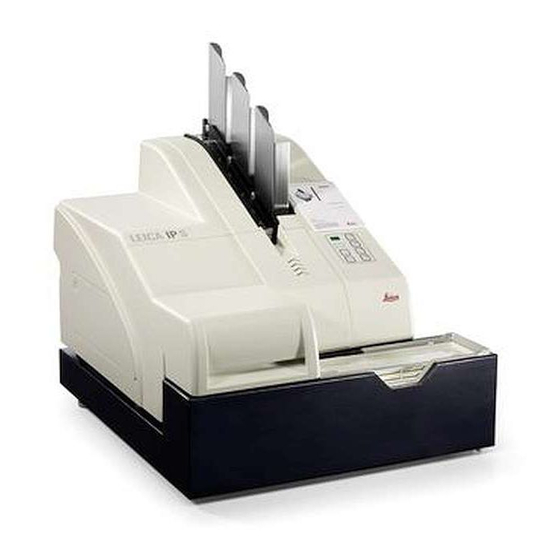
- Page 1 Instructions for Use Leica IP S - Printer for slides Leica IP S, V 1.9 RevD, English – 05/2013 Order No: 14 0601 85101, RevD...
- Page 3 Leica IP S Printer for slides Instructions for Use Leica IP S Order No. 14 0601 85101 RevD V 1.9 RevD, English - 05/2013 Always keep this manual with the instrument. Read carefully before working with the instrument.
- Page 5 Leica reserves the right to change technical following thorough investigation in this field. specifications as well as manufacturing process- We are under no obligation to update the pres- es without prior notice.
-
Page 6: Table Of Contents
Table of contents Important Information ....................... 6 Symbols in the text and their meanings ..................6 1.1.1 Symbols on the transport packaging and their meanings ............. 7 Qualification of personnel ......................8 Intended use of instrument ......................8 Instrument type ..........................8 Safety ............................ - Page 7 Storing the printer ........................55 Troubleshooting ........................59 Malfunctions ..........................59 Status messages ......................... 60 Error messages ........................... 61 Changing the flash bulb ......................64 Power failure ..........................64 Replacing the fuses ........................65 Warranty and Service ......................66 Leica IP S...
-
Page 8: Important Information
Important Information 1.1 Symbols in the text and their meanings Designates the serial number of the Warnings instrument. appear in a gray box and are marked by a warning triangle Order number for standard delivery or accessories. Notes i.e. important user information appear Symbol for alternating current in a gray box and are marked by an in- formation symbol... -
Page 9: Symbols On The Transport Packaging And Their Meanings
• Treatment code, e.g. HT (heat treatment), MB flows into the arrow-shaped (methyl bromide), and possibly DB (debarked) indicator window and sticks there permanently. Improp- er handling of the shipment is immediately detectable and can be proven defini- tively. Leica IP S... -
Page 10: Qualification Of Personnel
Important Information 1.2 Qualification of personnel 1.4 Instrument type • The Leica IP S may be operated by trained All information provided in these Instructions for laboratory personnel only. Use applies only to the instrument type indicated on the cover page. -
Page 11: Safety
Malfunctions that impede safety must be remedied immediately. For current information about applicable guidelines, please refer to the CE declaration of con- formity and on our Internet site at: http://www.LeicaBiosystems.com Leica IP S... -
Page 12: Warnings
Safety 2.2 Warnings The safety devices installed in this instrument by the manufacturer only constitute the basis for accident prevention. Primarily responsible for accident-free operation is above all the institution which owns the instrument and, in addition, the designated personnel who operates, services or repairs the instrument. - Page 13 • The painted surfaces and the control panel of the instrument are not resistant to xylene or acetone! • While working and during cleaning, no liquid may get into the interior of the instrument. Leica IP S...
-
Page 14: Instrument Components And Specifications
Instrument Components and Specifications 3.1 Overview—instrument 1 - Basic instrument 2 - Slide Magazines - Magazine no. 1 3 - Control panel 4 - Lid 5 - Cover—cartridge slot 6 - Unload station (manual) Fig. 2 Instructions for Use V 1.9 RevD - 05/2013... - Page 15 Prior to operation, the cleaning car- - Location plate tridge must be exchanged for an ink - External alarm jack cartridge - see Chapter 4.10, "Exchang- ing the cartridge". - Socket for printer cable Leica IP S...
-
Page 16: Technical Data
Instrument Components and Specifications 3.2 Technical data General Approvals: The instrument-specific approval marks are located at the rear panel of the instrument, next to the name plate. Nominal supply voltages: 100 to 120 V ~ +/- 10 % 200 to 240 V ~ +/- 10 % Nominal frequency: 50 to 60 Hz Power fuse:... - Page 17 ) Average value—exact speed in each individual case depending on system configuration and the software used. ) Average value—exact number of cassettes in each individual case depending on quantity being imprinted and on density of imprint. ) Measured in addressable dots per inch Leica IP S...
-
Page 18: Print Specifications
(23) can be imprinted in the Some slides have been coated over the print Leica IP S (see Fig. surface as well as the glass, which can create Printing directly onto the glass is not possible. - Page 19 Instrument Components and Specifications Tested and recommended print media for the Leica IP S ink jet printer Important! The use of other print media may result in unsatisfactory print quality and/or jamming of slides/ cassettes during the printing process! If the specimen slides you are currently using are not listed above, please contact your local Leica Biosystems representative.
-
Page 20: Print Specifications
Instrument Components and Specifications 3.3.2 Print specifications Print resolution The print head of the instrument has a preset resolution of 360 dpi in both directions (vertical and horizontal). Each printed line has a maximum height of 128 dots. This corresponds to a value of 9.03 mm. Therefore, a maximum of 2 lines can be printed on the slides. -
Page 21: Printing Bar Code
Data should never be printed as bar code only, but also as text (line of optical characters above or below the bar code), to ensure that no information is lost for the above reasons. Leica IP S... - Page 22 • Bar code style (1D or 2D) • Number and types of characters required in the bar code • The quality and resolution capabilities of the bar code reader As always, using Leica recommended print media will produce the highest quality print. However, it is highly recommended that any bar code solution be tested prior to implementation. Please check with your local representa- tive for details on achieving the maximum number of characters with 2 D bar codes.
-
Page 23: Resistance Against Reagents
All laboratories must perform their own tests to ensure that the ink is resistant against the vari- ous reagents the slides will subsequently be exposed to. A wide range of factors beyond Leica's control can have negative effects on the results. The test conditions stated below can therefore only serve as an outline for individual labora- tory test specifications. -
Page 24: Instrument Setup
Note this on the shipping doc- uments and check the ship- ment for possible damage. Only personnel authorized by Leica may unpack and install the instrument. Fig. 8 Instructions for Use V 1.9 - 08/2012... - Page 25 Fig. 11 • If the instrument was set up at its final area of use, remove the blue foam transport anchor Fig. 11) (pull upwards). Fig. 9 Leica IP S...
-
Page 26: Installing The Printer
Instrument Setup 4.3 Installing the printer When unpacking the printer, at least two people (one person on each side of the printer) are required to lift the printer out of the box and place it onto the laboratory bench. • Check instrument for damage (do not switch on in the case of damage!). -
Page 27: Standard Delivery-Packing List
Instrument Setup 4.4 Standard delivery—packing list The standard equipment of the Leica IP S includes the following parts: 1 Leica IP S, basic instrument without unload station 14 0601 33201 1 Cleaning cartridge (in the instrument) 14 0601 42865 1 UV ink cartridge Leica... -
Page 28: Installing The Manual Unload Station
Instrument Setup 4.5 Installing the manual unload station The unload station supplied consists of: 26 - Unload station 27 - Screening plate 28 - Collar screws (3 pcs.) 29 - Slotted screws with washers (2 pcs.) Install as follows (Fig. 13): • Open lid (4). -
Page 29: Automated Unload Station (Optional)
• Place the stack of trays (39) onto the lifting table (38) of the automated unload station. See chap- ter 5.2 for details on the lifting table controls. Fig. 14 Leica IP S... -
Page 30: Installing/Exchanging The Flash Bulb
Instrument Setup 4.7 Installing/exchanging the flash bulb Removing the old flash bulb Switch the instrument off and unplug it from power supply. Allow the flash tube to cool before re- moving it. Do not handle the flash tube with bare hands. Use a glove or tissue. • Open the lid (4, Fig. - Page 31 • The contact spring (44) has to touch the igni- tion wire (45) of the lamp after being inserted. • Swing the reflector downwards. Reinsert and retighten screw (49). • Close lid (4) of the instrument again. Fig. 22 Leica IP S...
-
Page 32: Filling And Inserting The Magazines
Instrument Setup 4.8 Filling and inserting the magazines Fig. 23 Fig. 24 Fig. 25 • Fill one of the magazines (48) with slides (49). While doing so, ensure that the surface to be imprinted (50) is on the left and facing upwards (Fig. 23). • So that the specimen slides are ejected cor- rectly, ensure that the specimen slides are inserted into the magazine accurately aligned above each other... - Page 33 • The magazine may be loaded with no more than 72 specimen slides to prevent problems during ejection. This corresponds to the lowest mark (75). • Even smaller loads will significantly improve the ability of the instrument to eject positively charged slides from the magazine. Fig. 28 Leica IP S...
-
Page 34: Electrical Connection
Instrument Setup 4.9 Electrical connection The instrument must be connected to a grounded power socket. Of the set of power cords supplied, be sure to use only the one that is appropriate for the local power supply (plug must fit on-site wall outlet). Back panel of instrument Connecting to power supply Electrical connections... -
Page 35: Exchanging The Cartridge
33). Do not reinstall a used transport plate (73), as it will no longer completely seal the print head. To prevent damage to the print head, always use the red location plate (70) when printing. Fig. 33 Leica IP S... - Page 36 Instrument Setup Exchanging the cartridge (continued) • Push the small lever (69, Fig. 32) back down into its original position. ð • Press any key of the control panel to reposition the print head and make the printer ready to operate. The last 30 sec- onds before the head closes are Caution! counted down.
- Page 37 • Directly next to the slot opening is a safety catch (86, Fig. 40). Moving this catch to the side secures the ink cartridge against falling out. This step is very important to ensure safe operation of the printer! Fig. 40 Leica IP S...
- Page 38 Instrument Setup • The sensor in the cartridge slot recognizes the presence of a Exchanging the cartridge (continued) new cartridge. ð • The indicator LED "Ink Empty" goes out, code "88" appears in the display. At this point, the instrument has to be "told" which type of cartridge has been inserted. There are three options: 1.
-
Page 39: Installing The Printer Driver
CD-ROM drive and enter the following path in the input field: (for English user interface) and con- X:\IP_Driver\IP_S\English firm with OK. " " is to be replaced by the letter corresponding to the drive containing the CD. Leica IP S... - Page 40 Instrument Setup 6. In the selection window, select PRINTERS IP-S (blue mark). If no (or other) selectable options are displayed, click on "HAVE DISK..." to return to the previous dialog box and repeat insertion of the path. 7. If the message shown on the left is displayed, the driver has already been installed on your PC on a previous occasion (e.g.
- Page 41 5. Click on CONFIGURE PORT... to open the Ports dialog box. Select the corresponding port and click on SETTINGS..The SETTINGS FOR... dia- log box opens up. Set BAUD RATE to 57600. Leave all other settings as shown in Fig. Leica IP S...
-
Page 42: Operation
Operation 5.1 Control panel functions The control panel • consists of a membrane keyboard with six pressure-sensitive keys (four of them with an LED, two LED displays and a two-figure seven- segment display. • controls the printer functions and the print jobs that are defined via the control software. • indicates current printer status and processes in progress. - Page 43 (Or that a magazine has been removed and replaced by another one containing cassettes of a different color). Pressing and holding LOADED for approx. 10 sec. in offline mode: Informs the printer that a cartridge has been exchanged. (For more information, see Chapter 4.10, "Exchanging the cartridge"). Leica IP S...
- Page 44 Operation ONLINE Interrupting a print job in progress. LED on: Printer is ready and waiting for a new print job. LED flashing: A data transmission is in progress or a print job is being carried out. • Pressing ONLINE while a print job is in progress interrupts printing. The current print job, however, is completed.
- Page 45 If no print job is in progress: • The printer switches to offline mode. • All steps are performed as described above. When operating continuously, the printer pauses regularly for inter- mediate print head cleans. Printing is interrupted for approximately 10 seconds, after which time the instrument automatically resumes operation. Leica IP S...
- Page 46 Operation TRAY LOAD Controls the movement of the lifting table of the automated unload station (optional) If your printer is not equipped with an automated unload station, no Place a stack of trays (37) onto the lifting table of function is assigned to this button! the unload station (Fig.
-
Page 47: Display Indications
6 minutes, "43" is displayed. Flash bulb has reached its maximum life. The flash lamp has reached the end of its specified service life and must be replaced. If this message is ignored, the resistance of subsequent printouts can be affected. Leica IP S... - Page 48 Operation Status messages (continued) Display Prompt requesting maintenance If this message is displayed, the instrument will be due for main- tenance within the next few weeks. Confirm the prompt pressing ERROR. After about 3 weeks the message will be displayed again and will not disappear from the screen when pressing ERROR.
-
Page 49: Alarm Functions
100 mA. A maximum voltage of 24 V DC must not be exceeded. For details on how to connect a remote alarm device to the Leica Printer IP S, please contact your local Leica sales office or the manufacturer directly. -
Page 50: Printer Driver Settings
Operation 5.4 Printer driver settings With the Leica IP S slide printer you can print slides from any Windows application allowing the user to individually configure the printing parameters. The description below refers to Mi- crosoft Wordpad, a program that is part of any Windows installation and therefore available on all PCs supported by the printer driver. - Page 51 Click on PROPERTIES... and ADVANCED... to access the ADVANCED OPTIONS menu. The ADVANCED... button does not exist under Windows NT 4.0. Clicking on PROPERTIES... in Windows NT leads you directly into the ADVANCED OPTIONS menu. Leica IP S...
- Page 52 Operation • In the PAPER SIZE menu you select the size of "ADVANCED OPTIONS" menu the imprintable zone of the Clicking onto the individual menu items opens up slide. Slide must be selected a pull-down menu to their right, where you can in this menu, otherwise select the desired parameters.
-
Page 53: Cleaning And Maintenance
Slide guiding mechanisms The IP S needs to be cleaned with a small vac- uum daily in the case of heavy use (or weekly in the case of light use) to remove any debris, especially glass dust. - Page 54 Cleaning and Maintenance Slide guiding mechanisms • Drying station (Fig. The chute must be clean. Caution! Sensitive electronics components are located in this area. Use no liquid in this area! Fig. 51 Drawer for broken glass • The drawer for broken glass (77) is located above the slot for the ink cartridge, behind the left cover (5).
-
Page 55: Clean Print Head
(on print head) and move the foam swab back and forth (Fig. 55) (approx. 10 times!). This procedure removes dried ink residues. Never rotate the swab—this can dam- age the nozzle plate of the print head. Fig. 55 Leica IP S... -
Page 56: General Maintenance
6.3 General maintenance Only authorized and qualified Leica service personnel may repair the instrument and access the instrument's internal components. The Leica IP S printer is virtually maintenance-free. To ensure smooth operation of the instrument over many years we do rec- ommend the following: • Clean the instrument thoroughly on a daily basis. -
Page 57: Storing The Printer
• Screw the red cap (87) to the shutter (88), close it securely and take the ink cartridge out completely. The ink cartridge cannot be used in another printer, because the ink level information is stored in the printer • Store the ink cartridge in a horizontal position itself. in a sealed container. Leica IP S... - Page 58 Cleaning and Maintenance Instructions for storage (continued) • Push a (new) cleaning cartridge as far as it will go into the shaft (Fig. 58). • Unscrew the red cap (85) one turn and slide the cartridge fully home. • Push the security latch (86, Fig. 57) back in front of the cartridge. Fig.
- Page 59 Turn the printer off and disconnect it from the power supply at this point to prevent damage to the print head. Never use a cleaning cartridge together with a location plate (70)! Do not reinstall a used transport plate (73), as it will no longer completely seal the print head. Leica IP S...
- Page 60 Cleaning and Maintenance Instructions for storage (continued) • Likewise, clean the removed removable disk (70) with the sealing lip with (clean) alcohol and a cleaning swab (89) (Fig. 62). • The sealing lip (71) must be completely free of ink residue. Check the sealing lip for dam- age. Do not reuse a replacement plate with a damaged sealing lip.
-
Page 61: Troubleshooting
All print jobs in the print queue are deleted. • If the same error continues to be displayed even after a Reset, switch the printer off via the power switch (back panel) and, after a short waiting period of approx. 30 sec., switch it back on. If this does not eliminate the problem either, call Leica Technical Service. Leica IP S... -
Page 62: Status Messages
Troubleshooting 7.2 Status messages (For additional information, refer also to Chap. 5.2) Display Meaning code "Mag. empty flashing" The printer is waiting for an individual cassette to be placed in the feeding chute for printing. "Mag. empty flashing" Magazine No. 1 empty "Mag. -
Page 63: Error Messages
Ambient temperature too high or electronics defective. The instrument remains disabled until the print head has cooled down to a temperature value within the permis- sible range. Check ambient temperature. No or incorrect voltage at ink print head. Call Leica Technical Service. Leica IP S... - Page 64 Close cover completely. Flash standby state not reached within the prescribed Call Leica Technical Service. time. Charging electronics defective. No flash or flash duration too short. Check whether flash bulb works – to do Flash bulb dirty or defective.
- Page 65 Error caused by application software. Print image exceeding the horizontal limit. Error caused by application software. The CRC test of the EEPROM returned an error when Call Leica Technical Service. the instrument was switched on. Internal firmware error or Call Leica Technical Service.
-
Page 66: Changing The Flash Bulb
Troubleshooting 7.4 Changing the flash bulb Code 13 is displayed when the flash bulb has reached its maximum service- able life. When code 13 is issued, the bulb has to be changed. For details on how to insert / replace the flash bulb, please refer to Chap- 4.7. -
Page 67: Replacing The Fuses
Insert the screwdriver into the slot in the fuse • The fuse holder is released and can be holder, push slightly inwards and at the same removed. time rotate the fuse holder 1/4 turn to the right. Leica IP S... -
Page 68: Warranty And Service
Leica Biosystems Nussloch GmbH guarantees that the contractual product delivered has been subjected to a comprehensive quality control proce- dure based on the Leica in-house testing standards, and that the product is faultless and complies with all technical specifications and/or agreed characteristics warranted. - Page 70 Leica Biosystems Nussloch GmbH Heidelberger Straße 17-19 D- 69226 Nussloch Tel.: +49 - (0) 6224 - 143 0 Fax: +49 - (0) 6224 - 143 268 Web: www.LeicaBiosystems.com...
Need help?
Do you have a question about the IP S and is the answer not in the manual?
Questions and answers