
Related Manuals for Avalue Technology SEAX-H81


Summary of Contents for Avalue Technology SEAX-H81
- Page 1 SEAX-H81 Intel® H81 Express Chipset ATX Motherboard User’s Manual Ed – 11 August 2014 Part No. E2047SA8100R...
- Page 2 Disclaimer Avalue Technology Inc. reserves the right to make changes, without notice, to any product, including circuits and/or software described or contained in this manual in order to improve design and/or performance. Avalue Technology assumes no responsibility or liability for the...
-
Page 3: Technical Support
SEAX-H81 User’s Manual otherwise specified. Applications that are described in this manual are for illustration purposes only. Avalue Technology Inc. makes no representation or warranty that such application will be suitable for the specified use without further testing or modification. -
Page 4: Table Of Contents
Gigabit LAN (RJ-45) connector (LAN) ........... 25 3.BIOS Setup ........................26 Introduction ....................27 Starting Setup ....................27 Using Setup ....................28 Getting Help ....................29 In Case of Problems ..................29 BIOS setup ....................30 4 SEAX-H81 User’s Manual... - Page 5 Install VGA Driver ..................53 Install LAN Driver (For Realtek 8111E Gigabit Ethernet) ......54 Install Audio Driver (For Realtek ALC662 HD Audio) ........55 Install USB3.0 Driver ..................56 Install ME Driver ................... 57 5. Mechanical Drawing ....................58 SEAX-H81 User’s Manual 5...
-
Page 6: Getting Started
Before you begin installing your single board, please make sure that the following materials have been shipped: Driver/Utility CD X 1 Serial ATA Signal Cable X 2 Motherboard X 1 IO Shield X 1 6 SEAX-H81 User’s Manual... -
Page 7: Document Amendment History
SEAX-H81 User’s Manual 1.3 Document Amendment History Revision Date Comment August 2014 Avalue Initial Release SEAX-H81 User’s Manual 7... -
Page 8: Manual Objectives
We strongly recommend that you study this manual carefully before attempting to set up SEAX-H81 series or change the standard configurations. Whilst all the necessary information is available in this manual we would recommend that unless you are confident, you contact your supplier for guidance. -
Page 9: Specifications
1 x Parallel port Internal I/O 2 x SATA III connector, 2 x SATA II connector Connector 1 x 2 x 5 pin, pitch 2.54mm connector for RS-232, Pin 9 without power SEAX-H81 User’s Manual 9... - Page 10 The Launch PXE OpROM policy can’t work at UEFI mode. But it can work normally under Legacy mode. Random Vibration Test (Operation) Test PSD: 0.00202G²/Hz, 1.0 Grms Random Vibration Test (Non-Operation) Test PSD: 0.01818G²/Hz 3 Grms Note: Specifications are subject to change without notice. 10 SEAX-H81 User’s Manual...
-
Page 11: Architecture Overview-Block Diagram
SEAX-H81 User’s Manual 1.6 Architecture Overview—Block Diagram The following block diagram shows the architecture and main components of SEAX-H81. Two 240-pin DIMM 1 x PS2 Keyboard Sockets Up to 16GB 1 x PCI-e x 16 1 x PS2 Mouse DDR3 1333 /1600MHz PCI-e x 16 Gen.3... -
Page 12: Hardware Configuration
SEAX-H81 User’s Manual 2. Hardware Configuration 12 SEAX-H81 User’s Manual... -
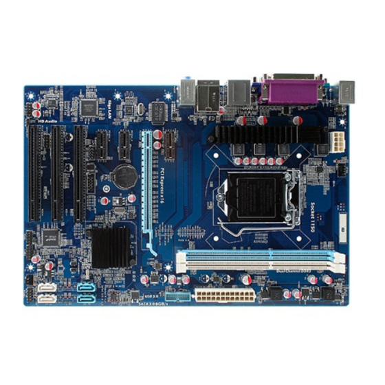
Page 13: Product Overview
SEAX-H81 User’s Manual 2.1 Product Overview SEAX-H81 User’s Manual 13... -
Page 14: Installation Procedure
4. Connect power supply to the board via the ATX Power. 5. Turn on the power. 6. Enter the BIOS setup by pressing the delete key during boot up. Use the "Save & Exit \ Restore Defaults" feature. 14 SEAX-H81 User’s Manual... -
Page 15: Jumper And Connector List
FPANEL Front Panel Switches 2 x 5 header, pitch 2.54 mm PCIEX16 PCI-e x 16 PCI Express x 1 connector 1 PCIE1_1 PCI Express x 1 connector 2 PCIE1_2 PCI Express x 1 connector 3 PCIE1_3 SEAX-H81 User’s Manual 15... - Page 16 2 x 5 header, pitch 2.54 mm AUDIO Audio connector JSPD_OUT Sony/Philips Digital Interface 1 x 3 header, pitch 2.54 mm PS2 KB_MS Keyboard & Mouse 2 x 5 header, pitch 2.54 mm JLPC LPC connector 16 SEAX-H81 User’s Manual...
-
Page 17: Setting Jumpers & Connectors
SEAX-H81 User’s Manual 2.4 Setting Jumpers & Connectors 2.4.1 Clear CMOS (JBAT1) Normal* Clear CMOS Define Open Normal Short Clear CMOS * Default 2.4.2 ME update (For Flash BIOS use) (JME) Open* Short * Default SEAX-H81 User’s Manual 17... -
Page 18: Keyboard Power Select Jumper (Jkb)
SEAX-H81 User’s Manual 2.4.3 Keyboard power select jumper (JKB) Disabled* Enabled Define Disabled Enabled * Default 2.4.4 Front Panel Switches (FPANEL) Signal PIN PIN Signal +HD_LED +P_LED -HD_LED -P_LED PWR_ON -PWR_ON 18 SEAX-H81 User’s Manual... -
Page 19: Sony/Philips Digital Interface (Jspd_Out)
SEAX-H81 User’s Manual 2.4.5 Sony/Philips Digital Interface (JSPD_OUT) Signal 2.4.6 Front Panel Audio Connection Header (F_AUDIO) Signal Signal PORT1L PORT1R PRESENCE# PORT2R SENSE1_RETURN SENSE_SEND PORT2L SENSE2_RETURN SEAX-H81 User’s Manual 19... -
Page 20: Usb Port Headers - Usb2.0 (Fusb1/2)
2.4.7 USB Port Headers - USB2.0 (FUSB1/2) Signal PIN PIN Signal DATA - DATA - DATA + DATA + FUSB1 FUSB2 USB Port Headers – USB3.0 (FUSB3.0) 2.4.8 Signal PIN PIN Signal SSRX- SSRX- SSRX+ SSRX+ SSTX- SSTX- SSTX+ SSTX+ 20 SEAX-H81 User’s Manual... -
Page 21: Atx +12V Power Connector (Pwr12V)
SEAX-H81 User’s Manual 2.4.9 ATX +12V Power connector (PWR12V) Signal PIN PIN Signal +12V +12V +12V +12V 2.4.10 ATX Power connector (ATXPWR) Signal PIN PIN Signal +3.3V +12V +12V 5VSB PWRGD PS-ON +3.3V -12V +3.3V +3.3V SEAX-H81 User’s Manual 21... -
Page 22: Serial Port Connector (Jcom)
SEAX-H81 User’s Manual 2.4.11 Serial port connector (JCOM) Signal PIN PIN Signal NDCDB NSINB NSOUTB NDTRB NDSRB NRTSB NCTSB NRIB 2.4.12 Speaker connector (SPEAK) Signal INTSPL+ INTSPR- 22 SEAX-H81 User’s Manual... -
Page 23: System Fan Connector (Sfan1)
SEAX-H81 User’s Manual 2.4.13 System Fan connector (SFAN1) Signal +12V Ground 2.4.14 CPU Fan connector (CFAN1) Signal Ground +12V Control SEAX-H81 User’s Manual 23... -
Page 24: General Purpose I/O Connector (Gpio)
SEAX-H81 User’s Manual 2.4.15 General purpose I/O connector (GPIO) Signal PIN PIN Signal VCC3 6779_GPI0 6779_GPO4 6779_GPI1 6779_GPO5 6779_GPI2 6779_GPO6 6779_GPI3 6779_GPO7 2.4.16 LPC connector (JLPC) Signal PIN PIN Signal L_AD3 VCC3 L_AD2 PLTRST_BUF L_AD1 L_FRAME_N L_AD0 CLK_PCI_DUG 24 SEAX-H81 User’s Manual... -
Page 25: Gigabit Lan (Rj-45) Connector (Lan)
Linked Green connection 1Gbps Blinking Data activity Green connection Note: This port allows Gigabit connection to a Local Area Network (LAN) through a network hub. Refer to the table below for the LAN port LED indications. SEAX-H81 User’s Manual 25... -
Page 26: Bios Setup
SEAX-H81 User’s Manual 3.BIOS Setup 26 SEAX-H81 User’s Manual... -
Page 27: Introduction
If you do not press the keys at the correct time and the system does not boot, an error message will be displayed and you will again be asked to. Press DEL to enter setup, F11 to popup menu SEAX-H81 User’s Manual 27... -
Page 28: Using Setup
Note: Some of the navigation keys differ from one screen to another. To Display a Sub Menu Use the arrow keys to move the cursor to the sub menu you want. Then press <Enter>. A “” pointer marks all sub menus. 28 SEAX-H81 User’s Manual... -
Page 29: Getting Help
AMI and your systems manufacturer to provide the absolute maximum performance and reliability. Even a seemingly small change to the chipset setup has the potential for causing you to use the override. SEAX-H81 User’s Manual 29... -
Page 30: Bios Setup
Note: BIOS setup screens shown in this chapter are for reference only, and may not exactly match what you see on your screen. Visit the Avalue website (www.avalue.com.tw) to download the latest product and BIOS information. 30 SEAX-H81 User’s Manual... -
Page 31: Advanced Bios Settings
This section allows you to configure your CPU and other system devices for basic operation through the following sub-menus. 3.6.2.1 ACPI Settings Item Options Description Enable ACPI Auto Disabled[Default] Enable or Disable BIOS ACPI Auto Enabled Configuration. Configuration Enable Hibernation Disabled Enables or Disables System ability to SEAX-H81 User’s Manual 31... -
Page 32: Onboard Device Configuration
Disabled HD Audio Controller Control of the Azalia audio. Enabled[Default] Disabled Azalia Internal HDMI Codec Azalia Internal HDMI Codec. Enabled[Default] Disabled USB Controller Control of USB ports. Enabled[Default] Disabled[Default] PCI Devices List PCI Device List. Enabled 32 SEAX-H81 User’s Manual... - Page 33 Maximum time the device will take before it properly reports itself to the Host Controller. ‘Auto’ Auto[Default] Device power-up delay Manual uses default value: for a Root port it is 100 ms, for a Hub port the delay is taken from Hub descriptor. SEAX-H81 User’s Manual 33...
-
Page 34: Cpu Configuration
Enabled for Windows XP and Linux. When Disabled Hyper-threading Disabled only one thread per enabled core is Enabled[Default] enabled. All[Default] Number of cores to enable in each processor Active Processor Cores package. Disabled[Default] Limit CPUID Maximum Disabled for Windows XP. Enabled 34 SEAX-H81 User’s Manual... -
Page 35: Intel® Rapid Start Technology
Enabled[Default] Disabled CPU C7 Report CPU C7 Enable/Disable CPU C7 report to OS. CPU C7s[Default] 3.6.2.4 Intel® Rapid Start Technology Item Options Description Intel® Rapid Start Disabled[Default] Enable or disable Intel® Rapid Start Technology. Enabled Technology SEAX-H81 User’s Manual 35... -
Page 36: Pch-Fw Configuration
SEAX-H81 User’s Manual 3.6.2.5 PCH-FW Configuration Item Options Description None[Default] MEBx Type. MEBx Type MiniMEBx Disabled[Default] MDES BIOS Status Code Enable/Disable MDES BIOS Status Code. Enabled Firmware Update Configuration Configure Management Engine Technology Parameters. 3.6.2.5.1 Firmware Update Configuration 36 SEAX-H81 User’s Manual... -
Page 37: Advanced Power Management
USB KB/MS WakeUp, for S3S4. Enabled[Default] Disabled LAN Wakeup LAN Wakeup by PME. Enabled[Default] Enable or disable System wake on alarm event. Disabled[Default] Wakeup By RTC When enabled, System will wake on the Enabled hr::min::sec specified. SEAX-H81 User’s Manual 37... -
Page 38: Nct6779D Super Io Configuration
3.6.2.7.1 Serial Port 0 Configuration Item Options Description Enabled[Default], Serial Port Enable or Disable Serial Port (COM). Disabled Auto[Default] IO=3F8h; IRQ=4; IO=3F8h; IRQ=3,4,5,6,7,10,11,12; Select an optimal setting for Super IO Change Settings IO=2F8h; IRQ=3,4,5,6,7,10,11,12; device. IO=3E8h; IRQ=3,4,5,6,7,10,11,12; IO=2E8h; IRQ=3,4,5,6,7,10,11,12; 38 SEAX-H81 User’s Manual... - Page 39 Select an optimal setting for Super IO Change Settings IO=2F8h; IRQ=3,4,5,6,7,10,11,12; device. IO=3E8h; IRQ=3,4,5,6,7,10,11,12; IO=2E8h; IRQ=3,4,5,6,7,10,11,12; Standard Serial Port Mode[Default] Change the Serial Port mode. Select Device Mode Full Duplex, ASKIR Mode <High Speed> or <Normal mode> Half Duplex, ASKIR Mode mode. SEAX-H81 User’s Manual 39...
- Page 40 (LPT/LPTE). Auto[Default] IO=378h; IRQ=5; Select an optimal setting for Super IO Change Settings IO=378h; IRQ=5,6,7,10,11,12; device. IO=278h; IRQ=5,6,7,10,11,12; IO=3BCh; IRQ=5,6,7,10,11,12; STD Printer Mode[Default] Device Mode SPP Mode Change the Printer Port mode. EPP-1.9 and SPP Mode 40 SEAX-H81 User’s Manual...
-
Page 41: Hw Monitor
The H/W Monitor shows the operating temperature, fan speeds and system voltages. Item Option Description Enable or Disable CPU Smart Fan. T1:30°C Duty:55T2:40°C Duty:70T3:50°C CPU Smart Fan Duty:80T4:60°C Duty:90risis:70°C Duty:100 PWM Output 0-100 Set CPU Fan Speed. 3.6.2.9 WatchDog Configuration SEAX-H81 User’s Manual 41... -
Page 42: Ami Graphic Output Protocol Policy
Fill Watchdog Timeout Value, 0 means Watchdog Timeout Value disabled. 3.6.2.10 AMI Graphic Output Protocol Policy Item Option Description Output Select Unknown Device Output Interface. Disabled[Default] Starts or stops the BIST on the integrated BIST Enable Enabled display panel. 42 SEAX-H81 User’s Manual... -
Page 43: Chipset
SEAX-H81 User’s Manual 3.6.3 Chipset Item Description South Bridge Configuration PCH Parameters. North Bridge Configuration System Agent (SA) Parameters. 3.6.3.1 South Bridge Configuration SEAX-H81 User’s Manual 43... -
Page 44: North Bridge Configuration
Aperture Size 256MB[Default] Select the Aperture Size. 512MB [32M] [64M][96M] [128M] [160M] Select DVMT 5.0 Pre-Allocated DVMT Pre-Allocated [192M] [224M] [256M] [Default] (Fixed) Graphics Memory size used by the Internal Graphics Device. [288M] [320M] [352M] [384M] [416M] 44 SEAX-H81 User’s Manual... -
Page 45: Boot Settings
Enables or disables Quiet Boot option. Enabled[Default] Auto: If the 1 boot HDD is GPT then Auto[Default] enable UEFI boot options, otherwise UEFI Boot Enabled disable. Enabled: Enable all UEFI boot Disabled options. Disabled: Disabled all UEFI boot options. SEAX-H81 User’s Manual 45... -
Page 46: Csm Parameters
Controls the execution of UEFI and UEFI only Launch Video OpROM policy Legacy Video OpROM. Legacy only[Default] For PCI devices other than Network, UEFI OpROM[Default] Other PCI device ROM priority Mass storage or Video defines which Legacy OpROM OpROM to launch. 46 SEAX-H81 User’s Manual... -
Page 47: Security
This setting specifies a password that must be entered to access the BIOS Setup Utility. If only the Administrator's password is set, then this only limits access to the BIOS setup program and is only asked for when entering the BIOS setup program. By default, no password is specified. SEAX-H81 User’s Manual 47... -
Page 48: Performance
SEAX-H81 User’s Manual 3.6.6 Performance 3.6.6.1 CPU Configuration Item Options Description Non Turbo Ratio Override 0-21[Default] Non Turbo Ratio Override. IA Core Current Max (1/8 Amp) IA Core Current Max (1/8 Amp). 48 SEAX-H81 User’s Manual... -
Page 49: North Bridge Configuration
Graphics Core Ratio Limit 0-10[Default] Graphics Core Ratio Limit. 3.6.6.2 North Bridge Configuration Item Options Description Automatic[Default] The selection of Performance Memory Manual Performance Memory Profiles Profiles which impacts memory sizing XMP Profile 1 behavior. XMP Profile 2 SEAX-H81 User’s Manual 49... -
Page 50: Overvoltage Configuration
1.50V[Default] 1.55V Memory Voltage (I/O) Set memory voltage. 1.60V 1.65V SVID Override Voltage Target, up to SVID Override Voltage Target(mV) 2500mV. CPU Voltage Offset(mV) CPU Voltage Offset, 0mV-998mV. GT Voltage Offset (mV) GT Voltage Offset, 0mV-998mV. 50 SEAX-H81 User’s Manual... -
Page 51: Drivers Installation
SEAX-H81 User’s Manual 4. Drivers Installation Note: Installation procedures and screen shots in this section are for your reference and may not be exactly the same as shown on your screen. SEAX-H81 User’s Manual 51... -
Page 52: Install Chipset Driver
Windows 7 operating system. Step 3. Select Install. Step 4. Select Finish to complete Step 1. Select Next to continue installation. Installation. Step 2. Select Accept to the next step. 52 SEAX-H81 User’s Manual... -
Page 53: Install Vga Driver
Windows 7 operating system. Step 3. Select Next to continue installation. Step 4. Select Next. Step 1. Select Next to start setup. Step 5. Select Finish to complete Step 2. Select Yes to the next step. Installation. SEAX-H81 User’s Manual 53... -
Page 54: Install Lan Driver (For Realtek 8111E Gigabit Ethernet)
Note: The installation procedures and Step 3. Click Finish to complete setup. screen shots in this section are based on Windows 7 operation system. Step 1. Click Next to Install. Step 2. Click Install to begin the installation. 54 SEAX-H81 User’s Manual... -
Page 55: Install Audio Driver (For Realtek Alc662 Hd Audio)
Note: The installation procedures and screen shots in this section are based on Windows 7 operation system. If the warning message appears while the installation process, click Continue to go Step1. Click Next to Install. Step 2. Select Finish to complete Installation. SEAX-H81 User’s Manual 55... -
Page 56: Install Usb3.0 Driver
Step 3. Select Next to continue installation. Step 4. Select Next to continue Step 1. Select Next to start setup. installation. Step 5. Select Finish to complete Step 2. Select Yes to the next step. Installation. 56 SEAX-H81 User’s Manual... -
Page 57: Install Me Driver
Windows 7 operating system. Step 3. Select Next to continue installation. Step 1. Select Next to start setup. Step 4. Select Finish to complete Installation. Step 2. Select Yes to the next step. SEAX-H81 User’s Manual 57... -
Page 58: Mechanical Drawing
SEAX-H81 User’s Manual 5. Mechanical Drawing 58 SEAX-H81 User’s Manual... - Page 59 SEAX-H81 User’s Manual Unit: mm SEAX-H81 User’s Manual 59...
- Page 60 SEAX-H81 User’s Manual Unit: mm 60 SEAX-H81 User’s Manual...
Need help?
Do you have a question about the SEAX-H81 and is the answer not in the manual?
Questions and answers