
Related Manuals for Avalue Technology ACP-GM45DS


Summary of Contents for Avalue Technology ACP-GM45DS
- Page 1 ACP-GM45DS Intel® GM45 socket μFC-PGA Core™ Duo / Core™ Solo/Core™ 2 Duo Mini ITX Main Board User’s Manual...
-
Page 2: Table Of Contents
ACP-GM45DS Contents Safety Information ......................4 Technical Support ......................5 Conventions Used in This Guide..................5 Packing List........................6 Revision History ........................7 Specifications Summary ....................8 Block Diagram........................11 Production Introduction ....................13 Before you Proceed ....................13 Motherboard Overview....................14 1.2.1 Placement Direction ........................14 1.2.2 Screw Holes ........................... 14 Motherboard Layout ....................15... - Page 3 LCD Inverter Connector (JBKL1)....................39 1.8.11 SPI Connector (JSPI1)....................... 40 1.8.12 Digital Audio Connector (SPDIF_OUT1) ................... 40 1.8.13 Serial SATA Connector (SATA1, SATA2, SATA3, SATA4) ............41 1.8.14 Serial SATA Power Connector (SATA_POWER1, SATA_POWER2)........42 1.8.15 USB 2.0 Connector (USB1, USB2).................... 42 ACP-GM45DS...
-
Page 4: Safety Information
ACP-GM45DS Safety Information Electrical safety To prevent electrical shock hazard, disconnect the power cable from the electrical outlet before relocating the system. When adding or removing devices to or from the system, ensure that the power cables for the devices are unplugged before the signal cables are connected. If possible, disconnect all power cables from the existing system before you add a device. -
Page 5: Technical Support
CAUTION: Information to prevent damage to the components when trying to complete a task. IMPORTANT: Instructions that you MUST follow to complete a task. NOTE: Tips and additional information to help you complete a task. ACP-GM45DS... -
Page 6: Packing List
Before you begin installing your single board, please make sure that the following materials have been shipped: 1 x Intel® 80I-GM4501-1000000 ACP-GM45DS Mini ITX Main board 1 x CD-ROM contains the followings: - User’s manual (this manual in PDF file) -... -
Page 7: Revision History
User’s Manual Revision History Revision Revision History Date V 1.0 First release for PCB 1.00 July 11, 2009 ACP-GM45DS... -
Page 8: Specifications Summary
ACP-GM45DS Specifications Summary Specifications System Supports Intel socket P Core 2 Duo / Core Duo / Core 2 Solo / Core Solo mobile CPU with 45nm process technology 667/800/1066 MHz BIOS AMI 32Mb SPI BIOS System Chipset Intel GM45/ICH9M-E Winbond W83627DHG-A... - Page 9 Intel 82574L PCI-E Gigabit Ethernet Controller (optional) Jumpers Label Function Note Normal * Clear CMOS CLRTC1 Clear CMOS SPDIF_OUT1 AAFP1 Front Panel Audio Connector Connectors Label Function Note JAMP1 Amplifier Connector Panel1 System Panel Connector JBKL1 LCD Inverter Connector ACP-GM45DS...
- Page 10 ACP-GM45DS Connectors JLVDS1 LVDS Connector +12V * Ring COMPWR2 COM1, COM2 RI/+5V/+12V COMPWR3 Selection COM23 COM Connector COM45 * Specifications are subject to change without notice.
-
Page 11: Block Diagram
User’s Manual Block Diagram ACP-GM45DS... - Page 12 ACP-GM45DS This chapter describes the main board features and the new technologies it supports. Product Product introduction introduction...
-
Page 13: Production Introduction
Before you install or remove any component, ensure that the ATX power supply is switched off or the power cord is detached from the power supply. Failure to do so may cause severe damage to the motherboard, peripherals, and/or components. ACP-GM45DS... -
Page 14: Motherboard Overview
ACP-GM45DS 1.2 Motherboard Overview Before you install the motherboard, study the configuration of your chassis to ensure that the motherboard fits into it. Refer to the chassis documentation before installing the motherboard. Make sure to unplug the power cord before installing or removing the motherboard. -
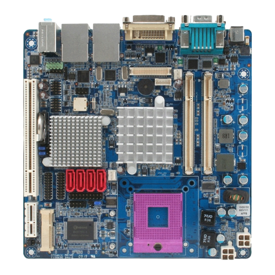
Page 15: Motherboard Layout
User’s Manual 1.3 Motherboard Layout ACP-GM45DS... -
Page 16: Layout Content List
ACP-GM45DS 1.3.1 Layout Content List Slots Label Function Note Page CF1A Compact Flash connector (Rear side) SODIMM_A1 200-pin SODIMM slot 1 SODIMM_B1 200-pin SODIMM slot 2 PCIEX1_1 PCI Express x1 Slot MINI_PCIE1 Mini PCI Express slot PCI1 PCI slot Jumpers... - Page 17 4 x 2 header, pitch 2.54mm SPDIF_OUT1 Digital Audio connector 4 x 1 header, pitch 2.54mm SATA1,2,3,4 Serial ATA connectors 1,2,3,4 7-pin header SATA_POWER1 SATA Power connectors 1,2 4-pin header SATA_POWER2 USB1,2 USB 2.0 connector 5 x 2 header, pitch 2.54mm ACP-GM45DS...
-
Page 18: Central Processing Unit (Cpu)
ACP-GM45DS 1.4 Central Processing Unit (CPU) The motherboard comes with a surface mount 478-pin designed for the Intel® socket 479P Core™ Duo / Core™ Solo / Core™ 2 Duo CPU with 65nm process. Take one of the marked corner (with gold triangle) on the CPU. -
Page 19: Installing The Cpu
Installing the CPU Locate the CPU socket on the motherboard. Before installing the CPU, make sure that the socket box is facing towards you. The processor socket comes with a screw to secure the processor, please unlock the screw first. ACP-GM45DS... - Page 20 ACP-GM45DS Position the CPU above the socket and the gold triangular mark on the CPU must align with pin 1 of the CPU socket. Carefully insert the CPU into the socket until it fits in place ‘Gold mark’. Turn the screw to the lock position.
-
Page 21: Installing The Cpu Heatsink And Fan
Orient the heatsink and fan assembly such that the CPU fan cable is closest to the CPU fan connector. Make sure each fastener is oriented as shown, with the narrow groove directed outward. ACP-GM45DS... - Page 22 ACP-GM45DS Push down two fasteners at a time in a diagonal sequence to secure the heatsink and fan assembly in place. Connect the CPU fan cable to the connector on the motherboard labelled CPU_FAN1. Do not forget to connect the fan cables to the fan connectors.
-
Page 23: Uninstalling The Cpu Heatsink And Fan
Carefully remove the heatsink and fan assembly from the motherboard. Refer to the documentation in the boxed or stand-alone CPU fan package for detailed information on CPU fan installation. ACP-GM45DS... -
Page 24: System Memory
ACP-GM45DS 1.5 System Memory 1.5.1 DIMM Sockets Location The motherboard comes with two 200-pin Double Data Rate 2 (DDR2) SODIMM sockets. A DDR2 module has the same physical dimensions as a DDR DIMM but has a 200-pin footprint compared to the 184-pin DDR DIMM. DDR2 DIMMs are notched differently to prevent installation on a DDR DIMM socket. -
Page 25: Memory Configurations
Make sure that the memory frequency matches the CPU FSB (Front Side Bus). Refer to the Memory frequency/CPU FSB synchronization table. Memory frequency/CPU FSB synchronization CPU FSB DDR 2 DIMM Type Memory Frequency 533/800MHz DDR2 667 Max clock Freq: 333MHZ; 667Mb/s DDR2 800 Max clock Freq: 400MHZ; 800Mb/s ACP-GM45DS... -
Page 26: Installing A Ddr2 Dimm
ACP-GM45DS 1.5.3 Installing a DDR2 DIMM Make sure to unplug the power supply before adding or removing DIMMs or other system components. Failure to do so may cause severe damage to both the motherboard and the components. Locate the DIMM socket on the board. -
Page 27: Removing A Ddr2 Dimm
Press the two ejector tabs on the slot outward simultaneously, and then pull out the DIMM module. Support the DIMM lightly with your fingers when pressing the ejector tabs. The DIMM might get damaged when it flips out with extra force. ACP-GM45DS... -
Page 28: Expansion Slots
ACP-GM45DS 1.6 Expansion Slots In the future, you may need to install expansion cards. The following sub sections describe the slots and the expansion cards that they support. Make sure to unplug the power cord before adding or removing expansion cards. Failure to do so may cause you physical injury and damage motherboard components. -
Page 29: Standard Interrupt Assignments
IRQ holder for PCI streeing* IRQ holder for PCI streeing* IRQ holder for PCI streeing* PS/2 Compatible Mouse Port* Numeric Data Processor Primary IDE Channel Secondary IDE Channel * There IRQs are usually available for ISA or PCI device. ACP-GM45DS... -
Page 30: Pci Slots
ACP-GM45DS 1.6.4 PCI Slots ACP-GM45DS has one PCI slots. The PCI slots support cards such as a LAN card, SCSI card, USB card, and other cards that comply with PCI specifications. The figure shows a LAN card installed on a PCI slot. -
Page 31: Jumpers
Hold down the <Del> key during the boot process and enter BIOS setup to re-enter data. Except when clearing the CMOS, never remove the cap on CLRTC jumper default position. Removing the cap will cause system boot failure! Normal (Default) Clear RTC ACP-GM45DS... -
Page 32: Com1 Ri/+5V/+12V Selection (Jcompwr3)
ACP-GM45DS 1.7.2 COM1 RI/+5V/+12V Selection (JCOMPWR3) JCOMPWR1 JCOMPWR2 (Default) +12V Ring 1.7.3 COM2 RI/+5V/+12V Selection (JCOMPWR2) JCOMPWR1 JCOMPWR2 (Default) +12V Ring... -
Page 33: Connectors
10/100 Mbps LAN controller allows 10/100 Mbps connection to a Local Area Network (LAN) through a network hub. ACT / LINK LED SPEED LED Status Description Status Description No link 10Mbps connection Orange Linked ORANGE 100Mbps connection Blinking Data activity GREEN 1Gbps connection ACP-GM45DS... - Page 34 ACP-GM45DS Label Function Description AUDIO1 Line-In port (Light Blue). This port connects a tape, CD, DVD player, or other audio sources. AUDIO1 Line-Out port (Lime) This port connects a headphone or a speaker. In 4-channel, 6-channel, and 8-channel configuration, the function of this port becomes Front Speaker Out.
-
Page 35: Amplifier Connector (Jamp1)
User’s Manual 1.8.2 Amplifier Connector (JAMP1) 1.8.3 Serial Port 2-3 Connector (COM2, COM3) 1.8.4 Serial Port 4-5 Connector (COM4,COM5) ACP-GM45DS... -
Page 36: Pu Fan Connector (Cpu_Fan1)
ACP-GM45DS 1.8.5 PU Fan Connector (CPU_FAN1) Do not forget to connect the fan cables to the fan connectors. Insufficient air flow inside the system may damage the motherboard components, and hardware monitoring errors can occur if you fail to plug this connector. -
Page 37: System Panel Connector (Fpio1)
The IDE LED lights up or flashes when data is read from or written to the HDD. Reset Button (2-pin RESET) This 2-pin connector is for the chassis-mounted reset button for system reboot without turning off the system power. ACP-GM45DS... -
Page 38: Digital I/O Connector
ACP-GM45DS 1.8.8 Digital I/O Connector 1.8.9 LVDS Connector (JLVDS1) -
Page 39: Lcd Inverter Connector (Jbkl1)
User’s Manual 1.8.10 LCD Inverter Connector (JBKL1) Signal Description Signal Signal Description Bright adjust. Vadj=0.75V ~ 4.25V (Recommended: 4.7KΩ, > 1/16W) ENBKL LCD backlight ON/OFF control signal ACP-GM45DS... -
Page 40: Spi Connector (Jspi1)
ACP-GM45DS 1.8.11 SPI Connector (JSPI1) 1.8.12 Digital Audio Connector (SPDIF_OUT1) This connector is for an additional Sony/Philips Digital Interface (S/PDIF) port(s). Connect the S/PDIF module cable to this connector, then install the module to a slot opening at the back of the system chassis. -
Page 41: Serial Sata Connector (Sata1, Sata2, Sata3, Sata4)
SATA3 SATA2 SATA4 Install the Windows® 2000 Service Pack 4 or the Windows® XP Service Pack1 before using Serial ATA. When using the connectors in Standard IDE mode, connect the primary (boot) hard disk drive to the SATA1 connector. ACP-GM45DS... -
Page 42: Serial Sata Power Connector (Sata_Power1, Sata_Power2)
ACP-GM45DS 1.8.14 Serial SATA Power Connector (SATA_POWER1, SATA_POWER2) These connectors provide power for SATA devices. Plug SATA Power Cable firmly then connect SATA power interface on hard drive or optical drive. SATA Power1 SATA Power2 SATA_POWER2 SATA_POWER1 1.8.15 USB 2.0 Connector (USB1, USB2) These connectors are for USB 2.0 ports.
Need help?
Do you have a question about the ACP-GM45DS and is the answer not in the manual?
Questions and answers