
Related Manuals for Avalue Technology EMX-CDD


Summary of Contents for Avalue Technology EMX-CDD
- Page 1 EMX-CDD Intel® Atom™ D2550 Process + NM10 Chipset Mini ITX Motherboard User’s Manual Ed – 30 September 2013 Part No. E2047CDDM00R...
-
Page 2: Technical Support
Avalue has come to be known. Your satisfaction is our primary concern. Here is a guide to Avalue’s customer services. To ensure you get the full benefit of our services, please follow the instructions below carefully. -
Page 3: Table Of Contents
2.4.20 Keyboard & Mouse connector (KM1) ............ 27 2.4.21 DC power-in connector (J14) ..............27 2.4.22 SATA Power connector 1~2 (SATA1~2_PWR) ........28 2.4.23 Speaker Headers (JSPK) ..............28 2.4.24 System Fan connector (SFAN1) ............29 EMX-CDD User’s Manual 3... - Page 4 3.6.6.3 Save Changes and Reset .............. 55 3.6.6.4 Discard Changes and Reset ............55 3.6.6.5 Save Changes ................55 3.6.6.6 Discard Changes ................55 3.6.6.7 Restore Defaults ................55 3.6.6.8 Save as User Defaults ..............55 3.6.6.9 Restore User Defaults ..............55 4 EMX-CDD User’s Manual...
- Page 5 4. Drivers Installation....................... 56 Install Chipset Driver ..................57 Install VGA Driver ..................59 Install LAN Driver (For Realtek 8111E Gigabit Ethernet) ......61 Install Audio Driver (For Realtek ALC661 HD Audio) ........62 5. Mechanical Drawing ....................63 EMX-CDD User’s Manual 5...
-
Page 6: Getting Started
Quick Installation Guide X 1 Driver/Utility CD X 1 Serial ATA Signal Cable X 1 Serial ATA Power Cable X 1 Screw X 2 Motherboard X 1 6 EMX-CDD User’s Manual... -
Page 7: Document Amendment History
EMX-CDD User’s Manual 1.3 Document Amendment History Revision Date Comment September Avalue Initial Release 2013 EMX-CDD User’s Manual 7... -
Page 8: Manual Objectives
We strongly recommend that you study this manual carefully before attempting to set up EMX-CDD series or change the standard configurations. Whilst all the necessary information is available in this manual we would recommend that unless you are confident, you contact your supplier for guidance. -
Page 9: Specifications
1 x 2 x 8 pin, pitch 2.54mm connector for front panel 1 x 2 x 2 pin ATX power connector for DC 12V input 1 x 2 x 20 pin, pitch 1.25mm connector for LVDS EMX-CDD User’s Manual 9... - Page 10 Operating 0%~90% relative humidity, non-condensing Humidity Size (L x W) 6.7" x 6.7" (170mm x 170mm) Weight 0.40 kg The USB keyboard and USB mouse can’t support wake up form S4 mode. Note: 10 EMX-CDD User’s Manual...
-
Page 11: Architecture Overview-Block Diagram
EMX-CDD User’s Manual 1.6 Architecture Overview—Block Diagram The following block diagram shows the architecture and main components of EMX-CDD. EMX-CDD User’s Manual 11... -
Page 12: Hardware Configuration
EMX-CDD User’s Manual 2. Hardware Configuration 12 EMX-CDD User’s Manual... -
Page 13: Product Overview
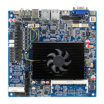
EMX-CDD User’s Manual 2.1 Product Overview EMX-CDD User’s Manual 13... -
Page 14: Installation Procedure
6. Enter the BIOS setup by pressing the delete key during boot up. Use the "Save & Exit \ Restore Defaults" feature. 7. If TFT panel display is to be utilized, make sure the panel voltage is correctly set before connecting the display cable and turning on the power. 14 EMX-CDD User’s Manual... -
Page 15: Jumper And Connector List
JU1~2 Jumper for FUSB2, MINIPCIE selection 1 x 3 header, pitch 2.54 mm JBAT1 Clear CMOS 1 x 3 header, pitch 2.54 mm J_MSATA_P Jumper for MSATA PWR selection 1 x 3 header, pitch 2.54 mm EMX-CDD User’s Manual 15... - Page 16 F_AUDIO1 Front Panel Audio Connection Header 2 x 5 header, pitch 2.54 mm Sony/Philips Digital Interface 1 x 5 header, pitch 2.54 mm JSPIDF1 IRDA connector (not supported) 1 x 5 header, pitch 2.00 mm IRDA 16 EMX-CDD User’s Manual...
-
Page 17: Setting Jumpers & Connectors
EMX-CDD User’s Manual 2.4 Setting Jumpers & Connectors 2.4.1 Clear CMOS (JBAT1) Normal* Clear CMOS Define * Default Normal Clear CMOS 2.4.2 Keyboard power select jumper (JKB1) Disabled* Enabled Define * Default Disabled Enabled EMX-CDD User’s Manual 17... -
Page 18: Jumper For Com2, Ir Selection (Jir1~2)
EMX-CDD User’s Manual 2.4.3 Jumper for COM2, IR selection (JIR1~2) JIR1 JIR2 Define * Default Note: IR is not functional. 2.4.4 Jumper for FUSB2, MINIPCIE selection (JU1~2) FUSB2* MINIPCIE Define * Default FUSB2 MINIPCIE 18 EMX-CDD User’s Manual... -
Page 19: Jumper For Mpcie_Wifi_Sata (Jp1~4)
M-SATA Define * Default MINIPCIE Note: SATA 2 bond together with M-SATA, it can only M-SATA work either way at one time. SATA2 2.4.6 Jumper for LVDS power (LVDS_PWR1) 3.3V Define Max current 3.3V * Default EMX-CDD User’s Manual 19... -
Page 20: Jumper For Inverter Power (Adj_Pwr1)
EMX-CDD User’s Manual 2.4.7 Jumper for inverter power (ADJ_PWR1) Define Max current * Default Serial port 1~6 – RI, USE JC1~6 PIN 9 selector (JC11~16) 2.4.8 USE JC1_JC6 PIN Option Define CLOSE OPEN USE JC_JC6 * Default 20 EMX-CDD User’s Manual... -
Page 21: Jumper For Serial Port 1~6 Selection (Jc1~6)
EMX-CDD User’s Manual 2.4.9 Jumper for Serial port 1~6 selection (JC1~6) +12V Define Max current +12V 2.4.10 Jumper for MSATA PWR selection (J_MSATA_P) M_PCIE* M_SATA Define * Default M_SATA M_PCIE EMX-CDD User’s Manual 21... -
Page 22: General Purpose I/O (Gpio)
General Purpose I/O (GPIO) Signal PIN PIN Signal +12V GPIO GPIO GPIO GPIO GPIO GPIO GPIO GPIO 2.4.12 Front Panel Switches (FPANEL1) Signal PIN PIN Signal 5VSB +HD_LED +P_LED -HD_LED -P_LED PS_ON +SPEAK -PS_ON RESET -RESET -SPEAK +SLPLED -SLPLED 22 EMX-CDD User’s Manual... -
Page 23: Lvds Connector (Jlvds1)
EMX-CDD User’s Manual 2.4.13 LVDS connector (JLVDS1) Signal PIN PIN Signal VDDPAEA VDDPAEA VDDPAEA VDDPAEA LVDS0_N0 Note: LVDS0_P0 Mapping connector DF13-40DS-1.25C (1.0mm). LVDS0_N1 LVDS0_P1 LVDS0_N2 LVDS0_P2 LVDS0_CLKN LVDS0_CLKP LVDS_DDCPDATA 32 LVDS_DDCPCLK LVDS0_N3 LVDS0_P3 LVDS_VCON EMX-CDD User’s Manual 23... -
Page 24: Printer (Jlpt)
2.4.14 Printer (JLPT) Signal PIN PIN Signal SLCT BUSY SLIN INIT 2.4.15 VGA connector (JVGA) Signal PIN PIN Signal DDC_CLK DDC_DATA VSYNC HSYNC BLUE GREEN Note: It can only use either D-SUB connector or Pin Header. 24 EMX-CDD User’s Manual... -
Page 25: Inverter Connector (Jinvert1)
EMX-CDD User’s Manual 2.4.16 Inverter connector (JINVERT1) Signal Max current BLEN 2.4.17 USB Connector 1~3 - USB2.0 (FUSB1~3) Signal PIN PIN Signal DATA- DATA- DATA+ DATA+ EMX-CDD User’s Manual 25... -
Page 26: Front Panel Audio Connection Header (F_Audio1)
EMX-CDD User’s Manual 2.4.18 Front Panel Audio Connection Header (F_AUDIO1) Signal Signal FROT1L PROT1R PRESENCE# PORT2R SENSE1_RETURN SENSE_SEND PORT2L SENSE2_RETURN 2.4.19 Serial port 1~6 connector (JCOM1~6) Signal PIN PIN Signal 26 EMX-CDD User’s Manual... -
Page 27: Keyboard & Mouse Connector (Km1)
EMX-CDD User’s Manual 2.4.20 Keyboard & Mouse connector (KM1) Signal PIN PIN Signal KB_DATA KB_CLK 2.4.21 DC power-in connector (J14) Signal PIN PIN Signal +12V +12V EMX-CDD User’s Manual 27... -
Page 28: Sata Power Connector 1~2 (Sata1~2_Pwr)
EMX-CDD User’s Manual 2.4.22 SATA Power connector 1~2 (SATA1~2_PWR) Signal Max current SATA1_PWR SATA2_PWR 2.4.23 Speaker Headers (JSPK) Signal INTSPR- INTSPR+ INTSPL- INTSPL+ Note: Support 3W X 2 speaker. Mapping Connector PHR-4 28 EMX-CDD User’s Manual... -
Page 29: System Fan Connector (Sfan1)
EMX-CDD User’s Manual 2.4.24 System Fan connector (SFAN1) Signal Ground +12V 2.4.25 CPU Fan connector (CFAN1) Signal Ground +12V Control EMX-CDD User’s Manual 29... -
Page 30: Bios Setup
EMX-CDD User’s Manual 3.BIOS Setup 30 EMX-CDD User’s Manual... -
Page 31: Introduction
If you do not press the keys at the correct time and the system does not boot, an error message will be displayed and you will again be asked to. Press DEL to enter setup, F11 to popup menu EMX-CDD User’s Manual 31... -
Page 32: Using Setup
Note: Some of the navigation keys differ from one screen to another. To Display a Sub Menu Use the arrow keys to move the cursor to the sub menu you want. Then press <Enter>. A “” pointer marks all sub menus. 32 EMX-CDD User’s Manual... -
Page 33: Getting Help
AMI and your systems manufacturer to provide the absolute maximum performance and reliability. Even a seemingly small change to the chipset setup has the potential for causing you to use the override. EMX-CDD User’s Manual 33... -
Page 34: Bios Setup
Note: BIOS setup screens shown in this chapter are for reference only, and may not exactly match what you see on your screen. Visit the Avalue website (www.avalue.com.tw) to download the latest product and BIOS information. 34 EMX-CDD User’s Manual... -
Page 35: Advanced Bios Settings
This section allows you to configure your CPU and other system devices for basic operation through the following sub-menus. Item Options Description Disable[Default] Controls the execution of UEFI and Legacy Launch PXE OpROM Enable PXE OpROM. 3.6.2.1 ACPI Settings EMX-CDD User’s Manual 35... -
Page 36: Rtc Wake Settings
Enable or Disable S3 Video Repost. Enabled 3.6.2.2 RTC Wake Settings Item Options Description Enable or Disable System wake on alarm Disabled[Default] Wake system with Fixed Time event. When enabled, System will wake on the Enabled hr::min::sec specified. 36 EMX-CDD User’s Manual... -
Page 37: Cpu Configuration
Execute Disable Bit Enabled OS (Windows Server 2003 SP1, Windows XP SP2, SuSE Linux 9.2, RedHat Enterprise 3 Update 3.) Disabled[Default] Disabled for Windows XP. Limit CPUID Maximum Enabled EMX-CDD User’s Manual 37... -
Page 38: Ide Configuration
EMX-CDD User’s Manual 3.6.2.4 IDE Configuration Item Options Description Disabled SATA Ports (0-3) Device Names if Present and SATA Controller(s) Enabled[Default] Enabled. IDE[Default] Configure SATA as Select a configuration for SATA Controller. AHCI 3.6.2.5 USB Configuration 38 EMX-CDD User’s Manual... -
Page 39: Power Management
Power On By PS/2 Keyboard. Password Enabled Power On By PS/2 Mouse Power On By PS/2 Mouse. Disabled[Default] Enabled Wake By PME Wake By PME. Disabled[Default] Power Off[Default] AC Power Loss Power On AC Power Loss. Last State EMX-CDD User’s Manual 39... -
Page 40: W83627Uhg Super Io Configuration
EMX-CDD User’s Manual 3.6.2.7 W83627UHG Super IO Configuration Item Description Serial Port 1/2/3/4/5/6 Set Parameters of Serial Port 1/2/3/4/5/6 (COMA/B/C/D/E/F). Configuration Parallel Port Configuration Set Parameters of Parallel Port (LPT/LPTE). 3.6.2.7.1 Serial Port 1 Configuration 40 EMX-CDD User’s Manual... - Page 41 Select an optimal setting for Change Settings IO=2F8h; IRQ=3,4,5,6,7,10,11,12; Super IO device. IO=3E8h; IRQ=3,4,5,6,7,10,11,12; IO=2E8h; IRQ=3,4,5,6,7,10,11,12; Standard Serial Port Mode[Default] Change the Serial Port mode. Device Mode None use Select <High Speed> or <Normal None use mode> mode. EMX-CDD User’s Manual 41...
- Page 42 Description Disabled Enable or Disable Serial Port Serial Port Enabled[Default] (COM). Auto[Default] IO=3E8h; IRQ=7; IO=3F8h; IRQ=3,4,5,6,7,10,11,12; IO=2F8h; IRQ=3,4,5,6,7,10,11,12; Select an optimal setting for Change Settings IO=3E8h; IRQ=3,4,5,6,7,10,11,12; Super IO device. IO=2E8h; IRQ=3,4,5,6,7,10,11,12; IO=2F0h; IRQ=3,4,5,6,7,10,11,12; IO=2E0h; IRQ=3,4,5,6,7,10,11,12; 42 EMX-CDD User’s Manual...
- Page 43 Description Disabled Enable or Disable Serial Port Serial Port Enabled[Default] (COM). Auto[Default] IO=2E8h; IRQ=7; IO=3F8h; IRQ=3,4,5,6,7,10,11,12; IO=2F8h; IRQ=3,4,5,6,7,10,11,12; Select an optimal setting for Change Settings IO=3E8h; IRQ=3,4,5,6,7,10,11,12; Super IO device. IO=2E8h; IRQ=3,4,5,6,7,10,11,12; IO=2F0h; IRQ=3,4,5,6,7,10,11,12; IO=2E0h; IRQ=3,4,5,6,7,10,11,12; EMX-CDD User’s Manual 43...
- Page 44 Description Disabled Enable or Disable Serial Port Serial Port Enabled[Default] (COM). Auto[Default] IO=2F0h; IRQ=7; IO=3F8h; IRQ=3,4,5,6,7,10,11,12; IO=2F8h; IRQ=3,4,5,6,7,10,11,12; Select an optimal setting for Change Settings IO=3E8h; IRQ=3,4,5,6,7,10,11,12; Super IO device. IO=2E8h; IRQ=3,4,5,6,7,10,11,12; IO=2F0h; IRQ=3,4,5,6,7,10,11,12; IO=2E0h; IRQ=3,4,5,6,7,10,11,12; 44 EMX-CDD User’s Manual...
- Page 45 Description Disabled Enable or Disable Serial Port Serial Port Enabled[Default] (COM). Auto[Default] IO=2E0h; IRQ=7; IO=3F8h; IRQ=3,4,5,6,7,10,11,12; IO=2F8h; IRQ=3,4,5,6,7,10,11,12; Select an optimal setting for Change Settings IO=3E8h; IRQ=3,4,5,6,7,10,11,12; Super IO device. IO=2E8h; IRQ=3,4,5,6,7,10,11,12; IO=2F0h; IRQ=3,4,5,6,7,10,11,12; IO=2E0h; IRQ=3,4,5,6,7,10,11,12; EMX-CDD User’s Manual 45...
- Page 46 EPP -1.9 and SPP Mode Change the Serial Port mode. Device Mode EPP -1.7 and SPP Mode Select <High Speed> or <Normal ECP Mode mode> mode. ECP and EPP 1.9 Mode ECP and EPP 1.7 Mode 46 EMX-CDD User’s Manual...
-
Page 47: Watchdogtimer Settings
EMX-CDD User’s Manual 3.6.2.8 WatchDogTimer Settings Item Options Description Disabled[Default] WatchDogTimer Setting. WatchDogTimer Enabled 3.6.2.9 W83627UHG HW Monitor The H/W Monitor shows the operating temperature, fan speeds and system voltages. EMX-CDD User’s Manual 47... -
Page 48: Chipset
EMX-CDD User’s Manual 3.6.3 Chipset Item Description Host Bridge Host Bridge Parameters. South Bridge South Bridge Parameters. 3.6.3.1 Host Bridge Item Options Description Intel IGD Configuration Config Intel IGD Settings. 48 EMX-CDD User’s Manual... - Page 49 None use Select the Active LFP Configuration. No No LVDS[Default] LVDS:VBIOS does not enable LVDS. Active LFP LVDS Int-LVDS:VBIOS enables LVDS driver by None use Integrated encoder. SDVO LVDS:VBIOS enables LVDS driver by SDVO encoder. eDP EMX-CDD User’s Manual 49...
-
Page 50: South Bridge
Enable/Disable USB Function. USB Function 5 USB Ports 6 USB Ports 7 USB Ports 8 USB Ports[Default] Disabled Onboard LAN 1/2 Conroller Enabled Enable/Disable Onboard Lan Controller. Auto[Default] PCIE1X Configuration PCI Express Root Port 1 Settings. 50 EMX-CDD User’s Manual... - Page 51 PCI Express Completion Timer TO Enabled Enable/Disable. Disabled[Default] Root PCI Express System Error on Fatal Error SEFE Enabled Enable/Disable. Disabled[Default] Root PCI Express System Error on Non-Fatal SENFE Enabled Error Enable/Disable. Disabled[Default] Root PCI Express System Error on SECE EMX-CDD User’s Manual 51...
-
Page 52: Boot Settings
Set display mode for Option ROM. Keep Current BIOS reaction on INT19 trapping by Option ROM: IMMEDIATE – execute Immediate INT19 Trap Response the trap right away; POSTPONED – Postponed[Default] execute the trap during legacy boot. 52 EMX-CDD User’s Manual... -
Page 53: Security
If only the User's password is set, then this is a power on password and must be entered to boot or enter the BIOS setup program. In the BIOS setup program, the User will have Administrator rights. By default, no password is specified. EMX-CDD User’s Manual 53... -
Page 54: Save & Exit
EMX-CDD User’s Manual 3.6.6 Save & Exit 3.6.6.1 Save Changes and Exit Exit system setup after saving the changes. 3.6.6.2 Discard Changes and Exit Exit system setup without saving any changes. 54 EMX-CDD User’s Manual... -
Page 55: Save Changes And Reset
This option saves a copy of the current BIOS settings as the User Defaults. This option is useful for preserving custom BIOS setup configurations. 3.6.6.9 Restore User Defaults This option restores all BIOS settings to the user defaults. This option is useful for restoring previously preserved custom BIOS setup configurations. EMX-CDD User’s Manual 55... -
Page 56: Drivers Installation
EMX-CDD User’s Manual 4. Drivers Installation Note: Installation procedures and screen shots in this section are for your reference and may not be exactly the same as shown on your screen. 56 EMX-CDD User’s Manual... -
Page 57: Install Chipset Driver
4.1 Install Chipset Driver Insert the Supporting DVD-ROM to DVD-ROM drive, click on “start” icon and it should show the index page of Avalue’s products automatically. If not, locate the folder HTML and choose the product from the targeted folder. - Page 58 EMX-CDD User’s Manual Step 8. Select Finish to complete Step 7. Select Next to the next step. Installation. 58 EMX-CDD User’s Manual...
-
Page 59: Install Vga Driver
4.2 Install VGA Driver Insert the Supporting DVD-ROM to DVD-ROM drive, click on “start” icon and it should show the index page of Avalue’s products automatically. If not, locate the folder HTML and choose the product from the targeted folder. - Page 60 EMX-CDD User’s Manual Step 7. Select Next to the next step. Step 8. Select Finish to complete Installation. 60 EMX-CDD User’s Manual...
-
Page 61: Install Lan Driver (For Realtek 8111E Gigabit Ethernet)
4.3 Install LAN Driver (For Realtek 8111E Gigabit Ethernet) Insert the Supporting DVD-ROM to DVD-ROM drive, and it should show the index page of Avalue’s products automatically. If not, locate Index.htm and choose the product from the menu left, or... -
Page 62: Install Audio Driver (For Realtek Alc661 Hd Audio)
4.4 Install Audio Driver (For Realtek ALC661 HD Audio) Insert the Supporting DVD-ROM to DVD-ROM drive, and it should show the index page of Avalue’s products automatically. If not, locate Index.htm and choose the product from the menu left, or link \Driver_Audio\Realtek\ALC661\EMX-CDD_Audio. -
Page 63: Mechanical Drawing
EMX-CDD User’s Manual 5. Mechanical Drawing EMX-CDD User’s Manual 63... - Page 64 EMX-CDD User’s Manual Unit: mm 64 EMX-CDD User’s Manual...
- Page 65 EMX-CDD User’s Manual Unit: mm EMX-CDD User’s Manual 65...
Need help?
Do you have a question about the EMX-CDD and is the answer not in the manual?
Questions and answers