
Related Manuals for Avalue Technology EAX-H81P


Summary of Contents for Avalue Technology EAX-H81P
- Page 1 EAX-H81P Intel® 4th Generation Core™ Refresh i7/ i5/ i3, Pentium® and Celeron® Processor ATX Motherboard With Intel® H81 Chipset User’s Manual Ed –03 December 2018 Part No. E2047AX8100R...
- Page 2 Disclaimer Avalue Technology Inc. reserves the right to make changes, without notice, to any product, including circuits and/or software described or contained in this manual in order to improve design and/or performance. Avalue Technology assumes no responsibility or liability for the...
-
Page 3: Technical Support
Applications that are described in this manual are for illustration purposes only. Avalue Technology Inc. makes no representation or warranty that such application will be suitable for the specified use without further testing or modification. -
Page 4: Product Warranty
A product returned without proof of the purchase date is not eligible for warranty service. Write the RMA number visibly on the outside of the package and ship it prepaid to your dealer. 4 EAX-H81P User’s Manual... -
Page 5: Table Of Contents
2.3.19 SPI connector (JSPI1) ........................31 2.3.20 Speaker connector (JSPK1) ......................31 2.3.21 Audio connector (JAUDIO1) ......................32 2.3.22 Miscellaneous setting connector (JFP1)..................32 2.3.23 CPU fan connector (CPUFAN1) ....................33 2.3.24 System fan connector 1 (SYSFAN1) ..................... 33 EAX-H81P User’s Manual... - Page 6 3.6.2.9.5 Serial Port 5 Configuration ....................58 3.6.2.9.6 Serial Port 6 Configuration ....................58 3.6.2.9.7 Parallel Port Configuration ..................... 59 3.6.2.9.8 Serial Port 7 Configuration ....................60 3.6.2.9.9 Serial Port 8 Configuration ....................60 3.6.2.9.10 Serial Port 9 Configuration ....................61 6 EAX-H81P User’s Manual...
- Page 7 Launch EFI Shell from filesystem device ................... 86 4. Drivers Installation....................... 87 Install Chipset Driver ....................88 Install VGA Driver ....................89 Install SOL Driver ....................90 Install Audio Driver (For Realtek ALC892 HD Audio) ..........91 Install LAN Driver ....................92 EAX-H81P User’s Manual...
- Page 8 EAX-H81P User’s Manual Install RST Driver ....................93 Install USB3.0 Driver ....................95 5. Mechanical Drawing ....................96 8 EAX-H81P User’s Manual...
-
Page 9: Getting Started
1.2 Packing List Before you begin installing your single board, please make sure that the following materials have been shipped: 1 x EAX-H81P motherboard 2 x SATA cables 1 x I/O shield ... -
Page 10: Document Amendment History
EAX-H81P User’s Manual 1.3 Document Amendment History Revision Date Comment December 2018 Avalue Initial Release 10 EAX-H81P User’s Manual... -
Page 11: Manual Objectives
We strongly recommend that you study this manual carefully before attempting to set up EAX-H81P or change the standard configurations. Whilst all the necessary information is available in this manual we would recommend that unless you are confident, you contact your supplier for guidance. -
Page 12: System Specifications
HDMI 1 x HDMI Audio AC97 Codec Realtek ALC892 HD Audio Decoding Controller with 3W Amplifier Audio Amp 1 x 4ohm 3W Amplifier Ethernet LAN Chip 2 x Intel® I211AT PCI-e Gigabit Ethernet Ethernet Gigabit Interface 12 EAX-H81P User’s Manual... - Page 13 1 x 1 x 3pin, pitch 2.54mm connector for COMS Clear 1 x Vertical type battery connector Co-lay 1 x 2 Pin Pitch 1.25mm horizontal type battery connector 1 x 2 x 10 pin, pitch 2.00mm connector for GPIO: 16 bits & +5VS Level SMBus EAX-H81P User’s Manual 13...
- Page 14 Size (L x W) (Please consult product engineers for the production feasibility if 12" x 9.6" (304.8mm x 243.84mm) the size is larger than 410x360mm or smaller than 80x70mm) Weight 0.60 kg OS Support BIOS Support: 14 EAX-H81P User’s Manual...
- Page 15 Operation System, while Firefox working normally. If installing Windows XP OS System, it is suggested to use USB DVD-ROM instead of SATA DVD-ROM. Due to Intel Haswell H81 Chipset limitation, 4K reslution quality report is not available. EAX-H81P User’s Manual 15...
-
Page 16: Architecture Overview-Block Diagram
EAX-H81P User’s Manual 1.6 Architecture Overview—Block Diagram The following block diagram shows the architecture and main components of EAX-H81P. 16 EAX-H81P User’s Manual... -
Page 17: Hardware Configuration
User’s Manual 2. Hardware Configuration EAX-H81P User’s Manual 17... -
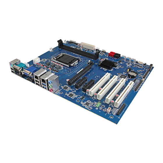
Page 18: Product Overview
EAX-H81P User’s Manual 2.1 Product Overview 18 EAX-H81P User’s Manual... -
Page 19: Jumper And Connector List
4 x 1 wafer, pitch 2.54mm function supported) 3 x 1 wafer, pitch 2.54mm SYSFAN2 System fan connector 2 JFP1 Miscellaneous setting connector 5 x 2 header, pitch 2.54 mm DIMM1/2 240 PIN DDR3 DIMM socket EAX-H81P User’s Manual 19... - Page 20 2 x 4 wafer, pitch 4.20mm ATX12V1 Power connector SATA1~4 Serial ATA connector 1~4 HDMI connector HDMI1 DP connector VGA connector VGA1 S/PDIF connector 1 x 4 header, pitch 2.54mm JSPDIF1 SMBus connector 5 x 1 header, pitch 2.54mm JSMB1 20 EAX-H81P User’s Manual...
-
Page 21: Setting Jumpers & Connectors
User’s Manual 2.3 Setting Jumpers & Connectors 2.3.1 Serial port 1 pin9 signal select (JRI1) Ring* +12V * Default 2.3.2 Serial port 2 pin9 signal select (JRI2) Ring* +12V * Default EAX-H81P User’s Manual 21... -
Page 22: Serial Port 3 Pin9 Signal Select (Jri3)
EAX-H81P User’s Manual 2.3.3 Serial port 3 pin9 signal select (JRI3) Ring* +12V * Default 2.3.4 AT/ATX Power Mode Select (JATATX1) * Default 22 EAX-H81P User’s Manual... -
Page 23: Clear Cmos (Jcmos1)
User’s Manual 2.3.5 Clear CMOS (JCMOS1) Protect* Clear CMOS * Default 2.3.6 COM2 RS485/422 connector (JCOM2B) Signal PIN PIN Signal 485TX- 422RX- 485TX+ 422RX+ EAX-H81P User’s Manual 23... -
Page 24: Com2 Rs485/422 Connector (Jcom3B)
EAX-H81P User’s Manual 2.3.7 COM2 RS485/422 connector (JCOM3B) Signal PIN PIN Signal 485TX-_C 422RX-_C 485TX+_C 422RX+_C 2.3.8 Serial Port2 connector (JCOM2A) Signal PIN PIN Signal NRXDB NDCDB# NDTRB# NTXDB NDSRB# NCTSB# NRTSB# JNRIB# 24 EAX-H81P User’s Manual... -
Page 25: Serial Port 3/4/5/6 Connector (Jcom3-6)
Signal PIN PIN Signal NRIF# NCTSF# NRTSF# NDSRF# NDTRF# NTXDF NRXDF NDCDF# NRIE# NCTSE# NRTSE# NDSRE# NDTRE# NTXDE NRXDE NDCDE# NRID# NCTSD# NRTSD# NDSRD# NDTRD# NTXDD NRXDD NDCDD# JNRIC# NCTSC# NRTSC# NDSRC# NDTRC# NTXDC NRXDC NDCDC# EAX-H81P User’s Manual 25... -
Page 26: Serial Port 3/4/5/6 Connector (Jcom7-10)
Signal PIN PIN Signal COM_DCD#_7 COM_RXD_7 COM_TXD_7 COM_DTR#_7 COM_DSR#_7 COM_RTS#_7 COM_CTS#_7 COM_RI#_7 COM_DCD#_8 COM_RXD_8 COM_TXD_8 COM_DTR#_8 COM_DSR#_8 COM_RTS#_8 COM_CTS#_8 COM_RI#_8 COM_DCD#_9 COM_RXD_9 COM_TXD_9 COM_DTR#_9 COM_DSR#_9 COM_RTS#_9 COM_CTS#_9 COM_RI#_9 COM_DCD#_10 COM_RXD_10 COM_TXD_10 COM_DTR#_10 COM_DSR#_10 COM_RTS#_10 COM_CTS#_10 COM_RI#_10 26 EAX-H81P User’s Manual... -
Page 27: General Purpose I/O Connector (Jdio1)
User’s Manual 2.3.11 General purpose I/O connector (JDIO1) Signal PIN PIN Signal SMB_CLK_9555_R 17 18 SMB_DATA_9555_R 2.3.12 ATX Power connector (ATXPWR1) Signal PIN PIN Signal +3.3V +3.3V -12V +3.3V PSON# PG_ATX +5VSB +12V +12V +3.3V EAX-H81P User’s Manual 27... -
Page 28: Power Connector (Atx12V1)
EAX-H81P User’s Manual 2.3.13 Power connector (ATX12V1) Signal PIN PIN Signal +12V +12V +12V +12V 2.3.14 SMBus connector (JSMB1) Signal SMB_CLK_MAIN SMB_DATA_MAIN SMB_ALERT#_MAIN +3.3V 28 EAX-H81P User’s Manual... -
Page 29: Usb Connector 7/8 (Jusb7/8)
User’s Manual 2.3.15 USB connector 7/8 (JUSB7/8) Signal Signal USBVCC_78 USBVCC_78A USB_R_DN8 USB_R_DN7 USB_R_DP8 USB_R_DP7 2.3.16 USB connector 11/12 (JUSB11/12) Signal Signal USBVCC_BC USBVCC_BC USB_R_DN12 USB_R_DN11 USB_R_DP12 USB_R_DP11 EAX-H81P User’s Manual 29... -
Page 30: Usb Connector 13/14 (Jusb13/14)
EAX-H81P User’s Manual 2.3.17 USB connector 13/14 (JUSB13/14) Signal Signal USBVCC_DE USBVCC_DE USB_R_DN14 USB_R_DN13 USB_R_DP14 USB_R_DP13 2.3.18 Battery connector (JBAT1) Signal +3.3V 30 EAX-H81P User’s Manual... -
Page 31: Spi Connector (Jspi1)
User’s Manual 2.3.19 SPI connector (JSPI1) Signal PIN PIN Signal +3.3V SPI_CS0#0 SPI_CLK_R SPI_MISO_R SPI_MOSI_R SPI_HOLD# 2.3.20 Speaker connector (JSPK1) Signal LSPK+ LSPK- RSPK+ RSPK - EAX-H81P User’s Manual 31... -
Page 32: Audio Connector (Jaudio1)
EAX-H81P User’s Manual 2.3.21 Audio connector (JAUDIO1) Signal PIN PIN Signal MIC2_L MIC2_R ACZ_DET#_R LINE2_RIN MIC2_JD LINE2_LIN LINE_JD 2.3.22 Miscellaneous setting connector (JFP1) Signal PIN PIN Signal HDD_LED+ PWR_LED+ HDD_LED- PWR_LED- RSET_BTN# PWRBTN# 32 EAX-H81P User’s Manual... -
Page 33: Cpu Fan Connector (Cpufan1)
User’s Manual 2.3.23 CPU fan connector (CPUFAN1) Signal +12V CPUFANIN CPUFANOUT 2.3.24 System fan connector 1 (SYSFAN1) Signal +12V SYSFANIN SYSFANOUT1 EAX-H81P User’s Manual 33... -
Page 34: System Fan Connector 2 (Sysfan2)
EAX-H81P User’s Manual 2.3.25 System fan connector 2 (SYSFAN2) Signal +12V SYS_FAN_IN_2 2.3.26 PS/2 keyboard & mouse connector (JKBMS1) Signal KBCK KBDT MSDT +5V_KBMS MSCK 34 EAX-H81P User’s Manual... -
Page 35: S/Pdif Connector (Jspdif1)
User’s Manual 2.3.27 S/PDIF connector (JSPDIF1) Signal SPDIF_O 2.3.28 External Speaker connector (JBZ1) Signal HDA_SPKR EAX-H81P User’s Manual 35... -
Page 36: Lpt Connector (Jlpt1)
PTD1 PT_PAR_INIT# PTD2 PT_SLIN# PTD3 PTD4 PTD5 PTD6 PTD7 ACK# BUSY SLCT 2.3.30 Auxiliary Panel connector (JAUXP1) Signal PIN PIN Signal SMB_CLK_MAIN CASEOPEN# ERROR_LED SMB_DATA_MAIN ERROR_LED# FRONT_LAN1_ACT 13 FRONT_LAN1_LINK100# 16 FRONT_LAN1_LINK1000# FRONT_LAN2_ACT 17 FRONT_LAN2_LINK100# 20 FRONT_LAN2_LINK1000# 36 EAX-H81P User’s Manual... -
Page 37: Bios Setup
User’s Manual 3.BIOS Setup EAX-H81P User’s Manual 37... -
Page 38: Introduction
If you do not press the keys at the correct time and the system does not boot, an error message will be displayed and you will again be asked to. Press F1 to Continue, DEL to enter SETUP 38 EAX-H81P User’s Manual... -
Page 39: Using Setup
Note: Some of the navigation keys differ from one screen to another. To Display a Sub Menu Use the arrow keys to move the cursor to the sub menu you want. Then press <Enter>. A “” pointer marks all sub menus. EAX-H81P User’s Manual 39... -
Page 40: Getting Help
BIOS Vendor and your systems manufacturer to provide the absolute maximum performance and reliability. Even a seemingly small change to the chipset setup has the potential for causing you to use the override. 40 EAX-H81P User’s Manual... -
Page 41: Bios Setup
<Enter> to accept and enter the sub-menu. 3.6.1 Main Menu This section allows you to record some basic hardware configurations in your computer and set the system clock. EAX-H81P User’s Manual 41... -
Page 42: System Language
Note: The BIOS setup screens shown in this chapter are for reference purposes only, and may not exactly match what you see on your screen. Visit the Avalue website (www.avalue.com.tw) to download the latest product and BIOS information. 42 EAX-H81P User’s Manual... -
Page 43: Advanced Menu
This section allows you to configure your CPU and other system devices for basic operation through the following sub-menus. 3.6.2.1 APCI Settings Item Options Description Disabled Enables or Disables System ability to Enable Hibernation Enabled[Default], Hibernate (OS/S4 Sleep State). This EAX-H81P User’s Manual 43... -
Page 44: Trusted Computing
Connecter S3/S4/S5 3.6.2.2 Trusted Computing Item Options Description Enables or Disables BIOS support for security Disabled[Default], device. O.S. will not show Security Device. Security Device Support Enabled TCG EFI protocol and INT1A interface will not be available. 44 EAX-H81P User’s Manual... -
Page 45: S5 Rtc Wake Settings
System will wake on the hr::min::sec Time Enabled specified Enable or disable System wake on alarm event. When Wake system with Dynamic Disabled[Default], enabled, System will wake on the current time + Time Enabled Increase minute(s) EAX-H81P User’s Manual 45... - Page 46 Wake up second 0-59. Item Options Description Enable or disable System wake on alarm event. Wake system with Dynamic Disabled When enabled, System will wake on the current Time Enabled[Default], time + Increase minute(s) Wake up minute increase 46 EAX-H81P User’s Manual...
-
Page 47: Cpu Configuration
3.6.2.4 CPU Configuration Item Options Description All[Default], Number of cores to enable in each processor Active Processor Cores package. When enabled, a VMM can utilize the additional Disabled Intel Virtualization Technology hardware capabilities provided by Vanderpool Enabled[Default], Technology. EAX-H81P User’s Manual 47... -
Page 48: Sata Configuration
Package C State limit AUTO 3.6.2.5 SATA Configuration Item Options Description Enabled[Default], SATA Configuration(S) Enable or disable SATA Device. Disabled SATA Mode Selection Determines how SATA controller(s) operate. AHCI[Default], Disabled SATA1 Enable or Disable SATA Port Enabled[Default], 48 EAX-H81P User’s Manual... -
Page 49: Pch-Fw Configuration
Identify the SATA port is connected to Solid SATA Device Type Drive[Default], State Drive or Hard Disk Drive. Solid State Drive 3.6.2.6 PCH-FW Configuration Item Options Description Disabled, MDES BIOS Status Code Enable/ Disable MDES BIOS Status Code. Enabled[Default] EAX-H81P User’s Manual 49... -
Page 50: Firmware Update Configuration
EAX-H81P User’s Manual 3.6.2.6.1 Firmware Update Configuration Item Option Description Disabled[Default], Me FW Image Re-Flash Enable/Disable Me FW Image Re-Flash function. Enabled 3.6.2.7 USB Configuration The USB Configuration menu helps read USB information and configures USB settings. 50 EAX-H81P User’s Manual... - Page 51 Mass storage device emulation type. ‘AUTO’ Auto[Default] Floppy enumerates devices according to their media format. Optical drives are emulated as ‘CDROM’, Mass Storage Devices Forced FDD Hard Disk drives with no media will be emulated according CD-ROM to a drive type. EAX-H81P User’s Manual 51...
-
Page 52: Nct6106D H/W Monitor
EAX-H81P User’s Manual 3.6.2.8 NCT6106D H/W Monitor Item Options Description Disabled Smart Fan Function Enable or Disable Smart Fan Enabled[Default], 3.6.2.8.1 Smart Fan Mode Configuration 52 EAX-H81P User’s Manual... - Page 53 Mode 7 Mode 8 Mode 9 SYS FAN Mode Mode 10 Manual or Smart Fan Mode selection. Mode 11 Mode 12 Mode 13 Mode 14 Mode 15 Mode 16 Mode 17 Mode 18 Mode 19 Mode 20 EAX-H81P User’s Manual 53...
-
Page 54: Super Io Configuration
Set Parameters of Serial Port 7 (COM7). Serial Port 8 Configuration Set Parameters of Serial Port 8 (COM8). Serial Port 9 Configuration Set Parameters of Serial Port 9 (COM9). Serial Port 10 Configuration Set Parameters of Serial Port 10 (COM10). 54 EAX-H81P User’s Manual... -
Page 55: Serial Port 1 Configuration
Set SIO watch dog timer. 60 Sec 2 Min 10 Min 30 Min Disabled[Default], ERP/Deep S5 Deep S5 for power saving Enabled 3.6.2.9.1 Serial Port 1 Configuration Item Option Description Disabled, Serial Port Enable or Disable Serial Port (COM). Enabled[Default] EAX-H81P User’s Manual 55... -
Page 56: Serial Port 2 Configuration
EAX-H81P User’s Manual 3.6.2.9.2 Serial Port 2 Configuration Item Option Description Disabled, Serial Port Enable or Disable Serial Port (COM). Enabled[Default] RS232[Default] COM2 Mode RS422 COM Mode RS232/RS422/RS485 RS485 3.6.2.9.3 Serial Port 3 Configuration 56 EAX-H81P User’s Manual... -
Page 57: Serial Port 4 Configuration
Disabled, Serial Port Enable or Disable Serial Port (COM). Enabled[Default] RS232[Default] COM3 Mode RS422 COM Mode RS232/RS422/RS485 RS485 3.6.2.9.4 Serial Port 4 Configuration Item Option Description Disabled, Serial Port Enable or Disable Serial Port (COM). Enabled[Default] EAX-H81P User’s Manual 57... -
Page 58: Serial Port 5 Configuration
EAX-H81P User’s Manual 3.6.2.9.5 Serial Port 5 Configuration Item Option Description Disabled, Serial Port Enable or Disable Serial Port (COM). Enabled[Default] 3.6.2.9.6 Serial Port 6 Configuration 58 EAX-H81P User’s Manual... -
Page 59: Parallel Port Configuration
Select an optimal setting for Super IO device. IO=278h;IRQ=5,6,7,10,11,12; IO=3BCh;IRQ=5,6,7,10,11,12; STD Printer Mode[Default] SPP Mode EPP-1.9 and SPP Mode Device Mode EPP-1.7 and SPP Mode Change the Printer Port mode. ECP Mode ECP -1.9 and EPP Mode ECP -1.7 and EPPMode EAX-H81P User’s Manual 59... -
Page 60: Serial Port 7 Configuration
EAX-H81P User’s Manual 3.6.2.9.8 Serial Port 7 Configuration Item Option Description Disabled, Serial Port Enable or Disable Serial Port (COM). Enabled[Default] 3.6.2.9.9 Serial Port 8 Configuration 60 EAX-H81P User’s Manual... -
Page 61: Serial Port 9 Configuration
User’s Manual Item Option Description Disabled, Serial Port Enable or Disable Serial Port (COM). Enabled[Default] 3.6.2.9.10 Serial Port 9 Configuration Item Option Description Disabled, Serial Port Enable or Disable Serial Port (COM). Enabled[Default] EAX-H81P User’s Manual 61... -
Page 62: Serial Port 10 Configuration
EAX-H81P User’s Manual 3.6.2.9.11 Serial Port 10 Configuration Item Option Description Disabled, Serial Port Enable or Disable Serial Port (COM). Enabled[Default] 3.6.2.10 Serial Port Console Redirection 62 EAX-H81P User’s Manual... -
Page 63: Com0
Mark: Parity bit is always. 1. Mark Space: Parity bit is always 0. Mark and Space Space Parity do not allow for error detection. They can be used as an additional data bit. EAX-H81P User’s Manual 63... - Page 64 The Settings specify if BootLoader is selected than Legacy console redirection is Redirection After BIOS Always Enable[Default] disabled before booting to Legacy OS. POST BootLoader Default value is Always Enable which means Legaacy console Redirection is enabled for Legacy OS. 64 EAX-H81P User’s Manual...
-
Page 65: Console Redirection Settings
Hardware RTS/CTS be sent to stop the data flow. Once the buffers are empty, a ‘start’ signal can be sent Software Xon/Xoff to re-start the flow. Hardware flow control uses two wires to send start/stop signals. EAX-H81P User’s Manual 65... -
Page 66: Network Stack
EAX-H81P User’s Manual 3.6.2.11 Network Stack Item Options Description Disabled[Default] Network Stack Enable/Disable UEFI Network Stack. Enabled Item Options Description Disabled Network Stack Enable/Disable UEFI Network Stack. Enabled[Default] 66 EAX-H81P User’s Manual... -
Page 67: Intel Rc Drivers Version Detail
Ipv4 PXE Support Enabled[Default] option will not be created. Enable Ipv6 PXE Boot Support. If disabled IPV6 PXE boot Disabled Ipv6 PXE Support Enabled[Default] option will not be created. 3.6.2.12 Intel RC Drivers Version Detail 3.6.3 Chipset EAX-H81P User’s Manual 67... -
Page 68: Pch-Io Configuration
EAX-H81P User’s Manual 3.6.3.1 PCH-IO Configuration Item Option Description Power Off[Default] Select AC power state when power is re-applied Restore AC Power Loss Power On after a power failure. Last State 3.6.3.1.1 PCI Express Configuration 68 EAX-H81P User’s Manual... -
Page 69: Pci Express Root Port 1 (Pcie2)
Control the PCI Express Root Port. Enabled[Default], Auto[Default] PCIe Speed Gen1 Select PCI Express Port Speed. Gen2 Detect Non-Compliance PCI Express Disabled[Default], Detect Non-Compliance Device Device. If enable, it will take more time at Enabled POST time. EAX-H81P User’s Manual 69... -
Page 70: Pci Express Root Port 3 (I21X #1)
Control the PCI Express Root Port. Enabled[Default], Auto[Default] PCIe Speed Gen1 Select PCI Express Port Speed. Gen2 Detect Non-Compliance PCI Express Disabled[Default], Detect Non-Compliance Device Device. If enable, it will take more time at Enabled POST time. 70 EAX-H81P User’s Manual... -
Page 71: Pci Express Root Port 4 (I21X #2)
Control the PCI Express Root Port. Enabled[Default], Auto[Default] PCIe Speed Gen1 Select PCI Express Port Speed. Gen2 Detect Non-Compliance PCI Express Disabled[Default], Detect Non-Compliance Device Device. If enable, it will take more time at Enabled POST time. EAX-H81P User’s Manual 71... -
Page 72: Pci Express Root Port 5 (Pcie3)
Control the PCI Express Root Port. Enabled[Default], Auto[Default] PCIe Speed Gen1 Select PCI Express Port Speed. Gen2 Detect Non-Compliance PCI Express Disabled[Default], Detect Non-Compliance Device Device. If enable, it will take more time at Enabled POST time. 72 EAX-H81P User’s Manual... -
Page 73: Pci Express Root Port 6 (It8892)
Enabled[Default], Disabled PCIE LTR Lock PCIE LTR Configuration Lock. Enabled[Default], Disabled Snoop Latency Override Manual Snoop Latency Override for PCH PCIE. Auto[Default], Disabled Non Snoop Latency Override Manual Non Snoop Latency Override for PCH PCIE. Auto[Default], EAX-H81P User’s Manual 73... -
Page 74: Usb Configuration
Smart Auto [Default], Auto XHCI Mode Enabled Mode of operation of xHCI controller. Disabled Manual Enabled BTCG Enabling/disabling trunk clock gating. Disabled[Default], USB Ports Per-Port Disable Disabled[Default], Control each of the USB ports (0~13) Control Enabled disabling. 74 EAX-H81P User’s Manual... -
Page 75: Usb Configuration
Disabled USB Port #4 (PS2USB1) Enable/Disable USB port. Enabled[Default], Disabled USB Port #5 (PS2USB1) Enable/Disable USB port. Enabled[Default], Disabled USB Port #6 (JUSB7/8) Enable/Disable USB port. Enabled[Default], Disabled USB Port #7 (JUSB7/8) Enable/Disable USB port. Enabled[Default], EAX-H81P User’s Manual 75... -
Page 76: Pch Azalia Configuration
Disabled = Azalia will be unconditionally Azalia Enabled disabled Enabled = Azalia will be Auto[Default], unconditionally Enabled Auto = Azalia will be enabled if present, disabled otherwise. 11db 14db Audio Gain Setting Gain Setting 11/14/19/25 dB 19db[Default], 25db 76 EAX-H81P User’s Manual... -
Page 77: System Agent (Sa) Configuration
User’s Manual 3.6.3.2 System Agent (SA) Configuration Item Option Description CPU SA Audio Device Enabled[Default], Enable or Disable CPU SA Audio Device. (B0:D3:F0) Disabled 3.6.3.2.1 Graphics Configuration EAX-H81P User’s Manual 77... - Page 78 DVMT Pre-Allocated Memory size used by the Internal Graphics Device. 320M 352M 384M 416M 448M 480M 512M 1024M 128M Select DVMT 5.0 Total Graphics Memory size used by 256M[Default] DVMT Total Gfx Mem the Internal Graphics Device. 78 EAX-H81P User’s Manual...
-
Page 79: Dmi Configuration
User’s Manual 3.6.3.2.2 DMI Configuration 3.6.3.2.3 NB PCIe Configuration Item Option Description GEN1 PEG0 - Gen X Configure PEG0 B0:D1:F0 Gen1-Gen3 GEN2[Default] Detect Non-Compliance Disabled[Default] Detect Non-Compliance PCI Express Device in PEG Device Enabled EAX-H81P User’s Manual 79... -
Page 80: Memory Configuration
1.5 GB Maximum Value of TOLUD. Dynamic 1.75 GB assignment would adjust TOLUD Max TOLUD 2 GB automatically based on largest MMIO length 2.25 GB of installed graphic controller 2.5 GB 2.75 GB 3 GB 3.25 GB 80 EAX-H81P User’s Manual... -
Page 81: Boot
Number of seconds to wait for setup activation Setup Prompt Timeout key. 65535(0xFFFF) means indefinite waiting. On[Default] Bootup NumLock State Select the keyboard NumLock state Disabled Quiet Boot Enables or disables Quiet Boot option Enabled[Default] Boot Option #1 Sets the system boot order. EAX-H81P User’s Manual 81... -
Page 82: Csm16 Parameters
EAX-H81P User’s Manual 3.6.4.1 CSM16 Parameters Item Option Description Force BIOS[Default] Option ROM Messages Set display mode for Option ROM Keep Current 3.6.4.2 CSM parameters 82 EAX-H81P User’s Manual... -
Page 83: Security
For PCI devices other than Network, Mass Other PCI device ROM priority Legacy OpROM storage or Video defines which OpROM to [Default] launch 3.6.5 Security Administrator Password Set setup Administrator Password User Password Set User Password EAX-H81P User’s Manual 83... -
Page 84: Secure Boot
Secure Boot User mode with enrolled Platform Key(PK) 2.CSM Enabled[Default], function is disabled Secure Boot mode selector. ‘Custom’ Mode enables Standard Secure Boot Mode users to change Image Execution policy and manage Custom[Default], Secure Boot Keys. 84 EAX-H81P User’s Manual... -
Page 85: Key Management
User’s Manual 3.6.5.1.1 Key Management Item Option Description Disabled Install Factory default Secure Boot Keys Default Key Provision Enabled[Default], when System is in Setup Mode. 3.6.6 Save and exit EAX-H81P User’s Manual 85... -
Page 86: Save Changes And Reset
Reset the system setup without saving any changes. 3.6.6.3 Restore Defaults Restore/Load Default values for all the setup options. 3.6.6.4 Launch EFI Shell from filesystem device Attempts to Launch EFI Shell application (Shell.efi) from one of the available filesystem devices. 86 EAX-H81P User’s Manual... -
Page 87: Drivers Installation
User’s Manual 4. Drivers Installation Note: Installation procedures and screen shots in this section are for your reference and may not be exactly the same as shown on your screen. EAX-H81P User’s Manual 87... -
Page 88: Install Chipset Driver
If the warning message appears while the installation process, click Continue to go on. Step 3. Select Install. Step1. Select Next to continue installation. Step 4. Select Finish to complete Installation. Step 2. Select Accept to the next step. 88 EAX-H81P User’s Manual... -
Page 89: Install Vga Driver
Windows 7 operation system. Step 3. Select Next to continue installation. Step 1. Select Next to start setup. Step 4. Click Next. Step 2. Select Yes to the next step. Step 5. Select Finish to complete Installation. EAX-H81P User’s Manual 89... -
Page 90: Install Sol Driver
Note: The installation procedures and screen shots in this section are based on Windows 7 operation system. Step 3. Click Next Step 4. Click Finish to complete the setup Step 1. Click Next to continue setup. Step 2. Click Next. 90 EAX-H81P User’s Manual... -
Page 91: Install Audio Driver (For Realtek Alc892 Hd Audio)
Windows 7 operation system. If the warning message appears while the installation process, click Continue to go on. Step2. installing Step1. Click Next to Install. Step 3. Select Finish to complete Installation. EAX-H81P User’s Manual 91... -
Page 92: Install Lan Driver
Note: The installation procedures and screen shots in this section are based on Windows 7 operation system. Step 3. Click Next. Step 1. Click Install Drivers and Software. Step 4. Click Next. Step 2. Click Next. Step 5. Click Install. 92 EAX-H81P User’s Manual... -
Page 93: Install Rst Driver
Note: The installation procedures and screen shots in this section are based on Windows 7 operation system. Step 2. Click Next. Step 1. Click Next to continue installation. Step 3. Click Next. EAX-H81P User’s Manual 93... - Page 94 EAX-H81P User’s Manual Step 4. Click Next. Step 6. Click Finish to complete setup. Step 5. Click Next. 94 EAX-H81P User’s Manual...
-
Page 95: Install Usb3.0 Driver
Windows 7 operating system. Step 3. Select Next to continue installation. Step 1. Select Next to start setup. Step 4. Click Next. Step 2. Select Yes to the next step. Step 5. Select Finish to complete Installation. EAX-H81P User’s Manual 95... -
Page 96: Mechanical Drawing
EAX-H81P User’s Manual 5. Mechanical Drawing 96 EAX-H81P User’s Manual... - Page 97 User’s Manual Unit: mm EAX-H81P User’s Manual 97...
- Page 98 EAX-H81P User’s Manual Unit: mm 98 EAX-H81P User’s Manual...
Need help?
Do you have a question about the EAX-H81P and is the answer not in the manual?
Questions and answers