
Related Manuals for Avalue Technology ENX-PNV


Summary of Contents for Avalue Technology ENX-PNV
- Page 1 ENX-PNV Intel® Atom™ N450 /D510 Nano-ITX Motherboard User’s Manual Ed. 03 November 2011 Part NO: E2047NPNV00R...
-
Page 2: Table Of Contents
ENX-PNV Contents Before you Proceed ....................11 Motherboard Overview .................... 12 1.2.1 Placement Direction ........................12 1.2.2 Screw Holes ........................... 12 Motherboard Layout ....................13 1.3.1 Layout Content List ........................14 System Memory ...................... 15 1.4.1 DIMM Sockets Location ......................... 15 1.4.2... - Page 3 Security Settings ........................54 2.2.4.2 Boot Setting Configuration ..................... 55 2.2.5 Exit ..............................56 2.2.5.1 Save Changes and Exit ......................57 2.2.5.2 Discard Changes and Exit ..................... 57 2.2.5.3 Discard Changes ........................58 2.2.5.4 Load Setup Defaults ......................58 ENX-PNV...
-
Page 4: Safety Information
ENX-PNV Safety Information Electrical safety To prevent electrical shock hazard, disconnect the power cable from the electrical outlet before relocating the system. When adding or removing devices to or from the system, ensure that the power cables for the devices are unplugged before the signal cables are connected. If possible, disconnect all power cables from the existing system before you add a device. -
Page 5: Safety Declaration
If a problem arises with your system and no solution can be obtained from the user’s manual, please contact your place of purchase or local distributor. Alternatively, please try the following help resources for further guidance. Visit the Avalue website: http://www.avalue.com.tw... -
Page 6: Packing List
ENX-PNV Packing List Before you begin installing your single board, please make sure that the following materials have been shipped: 1 x ENX-PNV Nano-ITX Motherboard 1 x CD-ROM contains the followings: User’s Manual in PDF file ... -
Page 7: Revision History
User’s Manual Revision History Revision Revision History Date V 1.0 First version for PCB 1.1 March, 2010 First version for PCB 1.1 November, 2011 ENX-PNV... -
Page 8: Specifications Summary
ENX-PNV Specifications Summary Specifications System Onboard Intel® Atom™ N450 SC/D510 DC 1.6GHz Processor DMI (2.5Gbps) x 4 Lanes AMI/Legacy 16 Mb SPI BIOS BIOS Intel® ICH8M System Chipset I/O Chipset Winbond W83627DHG-A One 200-pin SODIMM socket supports up to 2GB... -
Page 9: Block Diagram
User’s Manual Block Diagram ENX-PNV... - Page 10 ENX-PNV This chapter describes the main board features and the new technologies it supports. Product Product introduction introduction...
-
Page 11: Before You Proceed
Before you install or remove any component, ensure that the ATX power supply is switched off or the power cord is detached from the power supply. Failure to do so may cause severe damage to the motherboard, peripherals, and/or components. ENX-PNV... -
Page 12: Motherboard Overview
ENX-PNV 1.2 Motherboard Overview Before you install the motherboard, study the configuration of your chassis to ensure that the motherboard fits into it. Refer to the chassis documentation before installing the motherboard. Make sure to unplug the power cord before installing or removing the motherboard. -
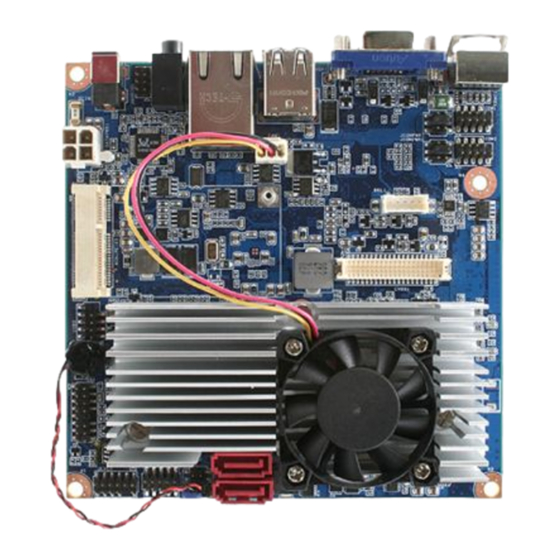
Page 13: Motherboard Layout
User’s Manual 1.3 Motherboard Layout ENX-PNV... -
Page 14: Layout Content List
ENX-PNV 1.3.1 Layout Content List Slots Label Function Note Page SO_DIMM 200-pin DDR2 SODIMM slot (Rear side) MINIPCIE1 Mini PCI-e Slot Compact Flash Card (Rear side) Jumpers Label Function Note Page CLRTC Clear CMOS 3 x 1 header, pitch 2.54mm... -
Page 15: System Memory
2 GB system memory when you installed one 2 GB DDR2 memory modules. This motherboard does not support memory modules FSB less than 667MHz.Make sure that the memory frequency matches the CPU FSB (Front Side Bus). Refer to the Memory frequency/CPU FSB synchronization table. ENX-PNV... -
Page 16: Installing A Ddr2 Dimm
ENX-PNV 1.4.3 Installing a DDR2 DIMM Make sure to unplug the power supply before adding or removing DIMMs or other system components. Failure to do so may cause severe damage to both the motherboard and the components. 1. Locate the DIMM socket on the board. -
Page 17: Removing A Ddr2 Dimm
1. Press the two ejector tabs on the slot outward simultaneously, and then pull out the DIMM module. Support the DIMM lightly with your fingers when pressing the ejector tabs. The DIMM might get damaged when it flips out with extra force. ENX-PNV... -
Page 18: Expansion Slots
ENX-PNV 1.5 Expansion slots 1.5.1 MiniPCE Express Location In the future, you may need to install expansion cards. The following sub-sections describe the slots and the expansion cards that they support. Make sure to unplug the power cord before adding or removing expansion cards. -
Page 19: Minipci Express Slot
6. Hold down the <Del> key during the boot process and enter BIOS setup to re-enter data. Except when clearing the CMOS, never remove the cap on the CLRTC jumper default position. Removing the cap will cause system boot failure! ENX-PNV... -
Page 20: Com1, Com2 Ri/+5V/+12V Select (Jcompwr1, Jcompwr2)
ENX-PNV Normal (Default) Clear CMOS 1.6.2 COM1, COM2 RI/+5V/+12V Select (JCOMPWR1, JCOMPWR2) RI (Default) +12V... -
Page 21: Connectors
In 4-channel, 6-channel, and 8-channel configuration, the function of this port becomes Front Speaker Out. DCIN1 12V DC-In Power Jack This power jack is connecting for 12V AC/DC pin 2.5mm power adapter . 12V 40W above is recommended . ENX-PNV... -
Page 22: Cpu Fan Connector (Fan1)
ENX-PNV 1.7.2 CPU Fan Connector (FAN1) This connector supports 12V smart fan for onboard heat-sink. Do not forget to connect the fan cable to the fan connector. Insufficient air flow inside the system may damage the motherboard components. ... -
Page 23: Lcd Inverter Connector (Jbkl)
This function will support the control of internal LVDS brightness. Signal Description Signal Signal Description For inverter with adjustable Backlight function, it is possible to control the LCD brightness through the VR signal. Vadj=0.75V ~ 4.25V (Recommended: 4.7KΩ, > 1/16W) ENBKL LCD backlight ON/OFF control signal ENX-PNV... -
Page 24: System Panel Connector (F_Panel)
ENX-PNV 1.7.5 System Panel Connector (F_PANEL) This connector supports several chassis-mounted functions, and provides additional USB 5 & 6 ports. System Power LED (2-pin PWRLED) This 2-pin connector is for the system power LED. Connect the chassis power LED cable to this connector. -
Page 25: Serial Port Connector (Com1 & Com2 )
These 2 connectors are for serial (COM) port. Connect the serial port module cable to this connector, and then install the module to a slot opening at the back of the system chassis. COM 1&2 1.7.7 Digital I/O Connector (JDIO) This connector supports 8-bit General purpose I/O function. ENX-PNV... -
Page 26: Sata Data Connector (Sata1&2)
ENX-PNV 1.7.8 SATA Data Connector (SATA1&2) These connectors are for the SATA signal cables to link SATA hard disk drives. SATA 1&2 1.7.9 SATA Power Connector (SATAPWR1) This connector is for the provided SATA power cable. This power supply cable is designed to fit this connector in only one orientation. -
Page 27: Mic-In & Line-In Connector (Jaudio1)
This USB connector complies with USB 2.0 specification that supports up to 480 Mbps connection speed. Never connect a 1394 cable to the USB connectors. Doing so will damage the motherboard! The USB module is purchased separately. ENX-PNV... - Page 28 ENX-PNV This chapter tells how to change the system settings through the BIOS setup menus. Detailed descriptions of the BIOS parameters are also provided. BIOS setup BIOS setup...
-
Page 29: Bios Setup Program
The BIOS setup screens shown in this section are for reference purposes only, and may not exactly match what you see on your screen. Visit the system builder’s website to download the latest BIOS file for this motherboard ENX-PNV... -
Page 30: Legend Box
ENX-PNV 2.1.1 Legend Box The keys in the legend bar allow you to navigate through the various setup menus Key(s) Function Description ← Select Screen ↑↓ Select Item Change Option / Field Enter Go to Sub Screen PGDN Next Page... -
Page 31: Bios Menu Screen
To access the menu items, press the up/down/right/left arrow key on the keyboard until the desired item is highlighted, then press [Enter] to open the specific menu. ENX-PNV... -
Page 32: Main
ENX-PNV 2.2.1 Main Use this menu for basic system configurations, such as time, date etc. 2.2.1.1 System Time The time format is <Hour> <Minute> <Second>. 2.2.1.2 System Date The date format is <Day>, <Month> <Date> <Year>. -
Page 33: Primary Ide Master
Select the type of SATA drive. Setting to Auto allows automatic selection of the appropriate SATA device type. Select CD/DVD if you are specifically configuring a CD-ROM/DVD-ROM drive. Select ARMD (ATAPI Removable Media Device) if your device is either a ZIP, LS-120, or MO drive. Configuration options: [Not Installed] [Auto] [CD/DVD] [ARMD] ENX-PNV... - Page 34 ENX-PNV LBA/Large Mode [Auto] Enables or disables the LBA mode. Setting to Auto enables the LBA mode if the device supports this mode, and if the device was not previously formatted with LBA mode disabled. Configuration options: [Disabled] [Auto] ...
-
Page 35: Ide Configuration
User’s Manual 2.2.1.4 IDE Configuration ATA/IDE Configuration [Enhanced] Allows you to set SATA Configuration function. Configuration options: [Compatible] [Enhanced] Configure SATA as [IDE] Allows you to set SATA as function[IDE] or [AHCI] ENX-PNV... -
Page 36: Ahci Setting
ENX-PNV 2.2.1.5 AHCI Setting AHCI Port0 & Port1 SATA AHCI functions for setting are [Auto] [Not Detected] further function settings after SATA devices detected are: AHCI Port0 [Disabled] [Enabled] AHCI Port1 [Disabled] [Enabled]... -
Page 37: System Information
This menu gives you an overview of the general system specifications. The BIOS automatically detects the items in this menu. AMI BIOS Display the auto-detected BIOS information. Processor Display the auto-detected CPU specification. System Memory Display the auto-detected system memory. ENX-PNV... -
Page 38: Advanced
ENX-PNV 2.2.2 Advanced The Advanced menu items allow you to change the settings for the CPU and other system devices. Take caution when changing the settings of the Advanced menu items. Incorrect field values can cause the system to malfunction. -
Page 39: Cpu Configuration
HTT requires only that the operating system supports multiple processors. It is recommended that you leave it at the default setting of Disabled. Only enable it if you intend to use Hyper-Threading Technology with an operating system that supports it. ENX-PNV... -
Page 40: Chipset
ENX-PNV 2.2.2.2 Chipset The items in this menu allow you to change the Chipset-related features. Select North Bridge Configuration and press <Enter> for further configuration options. DRAM Frequency [Auto] Allows you to set DRAM frequency , Configuration options: [Auto] [667MHz] [800MHz] It is recommended that you leave it at the default setting of Auto. - Page 41 - Flat Panel Type , Set for panel resolution , Configuration options: Type 1 640x480 Type 2 800x600 Type 3 1024x768 Type 4 1280x768 Type 5 1280x800 Type 6 1280x600 - Spread Spectrum Clock , Set for panel resolution , Configuration options: [Disable] [Enabled] ENX-PNV...
-
Page 42: Onboard Device Configuration
ENX-PNV 2.2.2.3 Onboard Device Configuration SMBUS Controller The options: [Enabled], [Disabled] HDA Controller The options: [Enabled], [Disabled] Onboard Rtl8111 LAN The options: [Enabled], [Disabled] Onboard LAN Boot The options: [Enabled], [Disabled] Mini PciE Port The options: [Enabled], [Disabled] ... -
Page 43: Usb Configuration
USB controller legacy mode is enabled. If no USB device is detected, the legacy USB support is disabled. Configuration options: [Disabled] [Enabled] [Auto] BIOS EHCI Hand-Off [Enabled] Allows you to enable support for operating systems without an EHCI hands off feature. Configuration options: [Disabled] [Enabled]. ENX-PNV... -
Page 44: Trusted Computing (Optional)
ENX-PNV 2.2.2.5 Trusted Computing (Optional) The items in this menu allow you to set the TPM (Trusted Platform Module) features. Select an item then press <Enter> to display the configuration options. TCG/TPM SUPPORT [YES] Allows you to enable or disable TCG/TPM 1.2 support in BIOS. -
Page 45: Pci Pnp
Play devices not required for boot. Configuration options: [No] [Yes] PCI Latency Timer [64] Allow the PCI Latency Timer to be adjusted. This option sets the latency of all PCI devices on the PCI bus. Configuration options: [32] [64] [96] [128] [160] [192] [224] [248] ENX-PNV... - Page 46 ENX-PNV Allocate IRQ to PCI VGA [Yes] Set this value to allow or restrict the system from giving the VGA adapter card an interrupt address. Configuration options: [No] [Yes] Palette Snooping [Disabled] Set this value to allow or restrict the system from giving the VGA adapter card an interrupt address.
- Page 47 This is the default setting. DMA Channel 3 DMA Channel 5 DMA Channel 6 Reserved This setting allows the specified DMA to be used by a legacy DMA Channel 7 ISA device. Reserved Memory Size [Disabled] Configuration options: [Disabled] [16K] [32K] [64K] ENX-PNV...
-
Page 48: Power
ENX-PNV 2.2.3 Power The Power menu items allows you to change the settings for the Advanced Power Management (APM). Select an item then press <Enter> to display the configuration options. 2.2.3.1 Suspend Mode Allows you to select the Advanced Configuration and Power Interface (ACPI) state to be used for system suspend. -
Page 49: Acpi Apic Support
<Arrow> keys to select an item. Use the <Plus> and <Minus> keys to change the value of the selected option. The settings are described on the following pages. The screen is shown below. Power Button Mode [On/Off] The option: [On/Off] [Suspend]. Resume On Ring The option: [Disabled] [Enabled]. ENX-PNV... - Page 50 ENX-PNV Resume On RTC Alarm When [Enabled], you can set the date and time at which the RTC (real-time clock) alarm awakens the system from suspend mode. PS/2 Keyboard WakeUP The option: [Disabled] [Enabled]. PS/2 Mouse WakeUP The option: [Disabled] [Enabled].
-
Page 51: Hardware Health Configuration
(RPM). If the fan is not connected to the motherboard, the field shows N/A. +12VIN / +5VIN / Vcore / VCC / VBAT [xxxx Voltage] The onboard hardware monitor automatically detects the voltage output through the onboard voltage regulators. ENX-PNV... - Page 52 ENX-PNV CPU FAN Profile Mode Allows you to select the CPU FAN profile mode. The options: [Disabled] [Optimal Mode]:Keeps a balance between CPU temperature and fan speed. [Silent Mode] :Keeps the system at a lower acoustic than Optimized mode with lower fan speed.
-
Page 53: Boot
User’s Manual 2.2.4 Boot The Boot menu items allow you to change the system boot options. Select an item then press <Enter> to display the sub-menu. ENX-PNV... -
Page 54: Security Settings
ENX-PNV 2.2.4.1 Security Settings The Security menu items allow you to change the system security settings. Select an item then press <Enter> to display the configuration options. Supervisor/User Password The Supervisor/User Password item on top of the screen shows the default Not Installed. -
Page 55: Boot Setting Configuration
The options: [Disabled], [Enabled] AddOn ROM Display Mode [Force BIOS] Set the display mode for ROM option. Configuration options: [Force BIOS] [Keep Current] Bootup Num-Lock [On] Allows you to select the power-on state for the NumLock. Configuration options: [Off] [On] ENX-PNV... -
Page 56: Exit
ENX-PNV Wait for ‘F1’ If Error [Enabled] When set to Enabled, the system waits for the F1 key to be pressed when error occurs. Configuration options: [Disabled] [Enabled]. 2.2.5 Exit The Exit menu items allow you to load the optimal or failsafe default values for the BIOS items, and save or discard your changes to the BIOS items. -
Page 57: Save Changes And Exit
Select this option only if you do not want to save the changes that you made to the setup program. If you made changes to fields other than System Date, System time, and Password, the BIOS asks for a confirmation before exiting. ENX-PNV... -
Page 58: Discard Changes
ENX-PNV 2.2.5.3 Discard Changes This option allows you to discard the selections you made and restore the previously saved values. After selecting this option, a confirmation appears. Select [OK] to discard any changes and load the previously saved values. 2.2.5.4 Load Setup Defaults This option allows you to load the setup default values for each of the parameters on the Setup menus.
Need help?
Do you have a question about the ENX-PNV and is the answer not in the manual?
Questions and answers