
Related Manuals for Avalue Technology EAX-Q35


Summary of Contents for Avalue Technology EAX-Q35
- Page 1 EAX-Q35 Intel® Q35 LGA775 socket for Intel® Core™ 2 Quad / Core™ 2 Duo ATX Motherboard User’s Manual Ver. 1.00...
-
Page 2: Table Of Contents
EAX-Q35 Contents Safety Information ......................4 Technical Support ......................5 Conventions Used in This Guide ..................5 Packing List ........................6 Revision History .......................7 Specifications Summary....................8 Block Diagram.........................11 Production Introduction ....................13 Before you Proceed ....................13 Motherboard Overview....................14 1.2.1 Placement Direction ........................14 1.2.2 Screw Holes ........................... 14 Motherboard Layout ....................15... - Page 3 BIOS Setup Program ....................48 2.1.1 Legend Box ............................ 49 2.1.2 List Box............................49 2.1.3 Sub-menu ............................49 BIOS Menu Screen ....................50 2.2.1 Main..............................51 2.2.2 Advanced ............................59 2.2.3 Power ............................. 74 2.2.4 Boot ..............................80 2.2.5 Exit..............................87 EAX-Q35...
-
Page 4: Safety Information
EAX-Q35 Safety Information Electrical safety To prevent electrical shock hazard, disconnect the power cable from the electrical outlet before relocating the system. When adding or removing devices to or from the system, ensure that the power cables for the devices are unplugged before the signal cables are connected. If possible, disconnect all power cables from the existing system before you add a device. -
Page 5: Technical Support
If a problem arises with your system and no solution can be obtained from the user’s manual, please contact your place of purchase or local distributor. Alternatively, please try the following help resources for further guidance. Visit the Avalue website for FAQ, technical guide, BIOS updates, driver updates, and other information: http://www.Avalue.com.tw... -
Page 6: Packing List
EAX-Q35 Packing List Before you begin installing your single board, please make sure that the following materials have been shipped: 1 x Intel Q35 ATX Main board 1 x CD-ROM contains the followings: - User’s manual (this manual in PDF file) -... -
Page 7: Revision History
User’s Manual Revision History Revision Revision History Date V 1.00 First release for PCB 1.00 January 1, 2009 EAX-Q35... -
Page 8: Specifications Summary
EAX-Q35 Specifications Summary Intel® Q35 LGA775 socket for Intel® Core™2 Quad / Core™2 Duo / Processors Compatible with Intel® 05B/05A/06 processors Support Intel® next generation 45nm Multi-Core CPU Intel Q35 + ICH9R Chipset Chipset Four 240-pin DIMMs up to 8 GB Dual Channel DDR2 800/667... - Page 9 Back I/O Port 1 x PS/2 Keyboard 1 x PS/2 Mouse 1 x VGA port 1 x Parallel port Back Panel 1 x COM Port 2 x RJ45 port 4 x USB 2.0/1.1 1 x Audio Jack (3 ports) EAX-Q35...
- Page 10 EAX-Q35 Specifications Summary Internal I/O Connector 4 x USB connectors support additional 8 USB ports (with 5V dual) 1 x Floppy disk drive connector 1 x IDE connector 6 x SATA connectors 1 x CPU Fan header 1 x Chassis Fan header...
-
Page 11: Block Diagram
User’s Manual Block Diagram EAX-Q35... - Page 12 EAX-Q35 This chapter describes the main board features and the new technologies it supports. 1 1 1 1 1 1 1 1 Product Product introduction introduction...
-
Page 13: Production Introduction
ON, in sleep mode, or in soft-off mode. This is a reminder that you should shut down the system and unplug the power cable before removing or plugging in any motherboard component. The illustration below shows the location of the onboard LED. EAX-Q35... -
Page 14: Motherboard Overview
EAX-Q35 1.2 Motherboard Overview Before you install the motherboard, study the configuration of your chassis to ensure that the motherboard fits into it. Refer to the chassis documentation before installing the motherboard. Make sure to unplug the power cord before installing or removing the motherboard. -
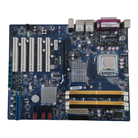
Page 15: Motherboard Layout
User’s Manual 1.3 Motherboard Layout EAX-Q35... -
Page 16: Layout Content List
EAX-Q35 1.3.1 Layout Content List Slots Label Function Note Page DIMM_A1 240-pin DIMM slot 1 DIMM_A2 240-pin DIMM slot 2 DIMM_B1 240-pin DIMM slot 3 DIMM_B2 240-pin DIMM slot 4 PCIEX1_1 PCI express x1 slot PCIEX16 PCI express x16 slot... - Page 17 USB 2.0 Connector 5 x 2 header, pitch 2.54mm USB78 USB 2.0 Connector 5 x 2 header, pitch 2.54mm USB910 USB 2.0 Connector 5 x 2 header, pitch 2.54mm USB1112 USB 2.0 Connector 5 x 2 header, pitch 2.54mm EAX-Q35...
-
Page 18: Central Processing Unit (Cpu)
EAX-Q35 1.4 Central Processing Unit (CPU) The motherboard comes with a surface mount LGA775 socket designed for the Intel® LGA775 Core™2 Quad / Core™2 Duo CPU processors. Make sure the AC power is off before you install the CPU. If installing a dual-core CPU, connect the CPU fan cable to the CPU_FAN connector to ensure system stability. -
Page 19: Installing The Cpu
Press the load lever with your thumb (A), then move it to the left (B) until it is released from the retention tab. To prevent damage to the socket pins, do not remove the PnP cap unless you are installing a CPU. Lift the load lever in the direction of the arrow to a 135º angle. EAX-Q35... - Page 20 EAX-Q35 Lift the load plate with your thumb and forefinger to a 100º angle (A), then push the PnP cap from the load plate window to remove (B). Position the CPU over the socket, making sure that the gold triangle is on the bottom-left corner of the socket then fit the socket alignment key into the CPU notch.
-
Page 21: Installing The Cpu Heatsink And Fan
Orient the heatsink and fan assembly such that the CPU fan cable is closest to the CPU fan connector. Make sure each fastener is oriented as shown, with the narrow groove directed outward. EAX-Q35... - Page 22 EAX-Q35 Push down two fasteners at a time in a diagonal sequence to secure the heatsink and fan assembly in place. Connect the CPU fan cable to the connector on the motherboard labelled CPU_FAN. Do not forget to connect the fan cables to the fan connectors.
-
Page 23: Uninstalling The Cpu Heatsink And Fan
Rotate each fastener counter-clockwise. Pull up two fasteners at a time in a diagonal sequence to disengage the heatsink and fan assembly from the motherboard Carefully remove the heatsink and fan assembly from the motherboard. EAX-Q35... - Page 24 EAX-Q35 Rotate each fastener clockwise to ensure correct orientation when reinstalling. The narrow end of the groove should point outward after resetting. (The photo shows the groove shaded for emphasis.) Refer to the documentation in the boxed or stand-alone CPU fan...
-
Page 25: System Memory
A DDR2 module has the same physical dimensions as a DDR DIMM but has a 240-pin footprint compared to the 184-pin DDR DIMM. DDR2 DIMMs are notched differently to prevent installation on a DDR DIMM socket. The following figure illustrates the location of the sockets: EAX-Q35... -
Page 26: Memory Configurations
EAX-Q35 1.5.2 Memory Configurations You can install 128MB, 256MB, 512MB, 1GB and 2GB DDR2 SDRAM DIMMs into the SODIMM sockets using the memory configurations in this section. Installing DDR2 DIMM other than the recommended configurations may cause memory sizing error or system boot failure. -
Page 27: Installing A Ddr2 Dimm
Simultaneously press the retaining clips outward to unlock the DIMM. Remove the DIMM from the socket. Support the DIMM lightly with your fingers when pressing the retaining clips. The DIMM might get damaged when it flips out with extra force. EAX-Q35... -
Page 28: Expansion Slots
EAX-Q35 1.6 Expansion Slots In the future, you may need to install expansion cards. The following sub‑sections describe the slots and the expansion cards that they support. Make sure to unplug the power cord before adding or removing expansion cards. Failure to do so may cause you physical injury and damage motherboard components. -
Page 29: Standard Interrupt Assignments
IRQ holder for PCI streeing* IRQ holder for PCI streeing* IRQ holder for PCI streeing* PS/2 Compatible Mouse Port* Numeric Data Processor Primary IDE Channel Secondary IDE Channel * There IRQs are usually available for ISA or PCI device. EAX-Q35... -
Page 30: Pci Slot
EAX-Q35 1.6.4 PCI Slot This motherboard has five PCI slots. The PCI slots support cards such as a LAN card, SCSI card, USB card, and other cards that comply with PCI specifications. The figure shows a LAN card installed on a PCI slot. -
Page 31: Jumpers
Hold down the <Del> key during the boot process and enter BIOS setup to re-enter data. Except when clearing the CMOS, never remove the cap on CLRTC jumper default position. Removing the cap will cause system boot failure! Normal (Default) Clear CMOS EAX-Q35... -
Page 32: Chassis Intrusion Connector (Chssis)
EAX-Q35 1.7.2 Chassis Intrusion Connector (CHSSIS) 1.7.3 COM1, 2, 3, 4 RI/+5V/+12V Select (JCOMPWR1, 2, 3, 4) RI * +12V JCOMPWR1 JCOMPWR2, 4, 3, 5, 7, 6... -
Page 33: Com4 Rs-242/422/485 Select (Jcompwr5, 6, 7)
User’s Manual 1.7.4 COM4 RS-242/422/485 Select (JCOMPWR5, 6, 7) JCOMPWR5 JCOMPWR6,7 RS-232 * RS-422 RS-485 JCOMPWR1 JCOMPWR2, 4, 3, 5, 7, 6 EAX-Q35... -
Page 34: Connectors
EAX-Q35 1.8 Connectors 1.8.1 Rear Panel Connectors Label Function Description KBMS PS/2 mouse connector The standard PS/2 mouse DIN connector is for a PS/2 mouse. Parallel port connector This 25-pin parallel port is a standard printer port that supports Enhanced Parallel... - Page 35 USB 2.0 devices. VGA port This 15-pin port is for a VGA monitor or other VGA-compatible devices. COM1 Serial port connector D-Sub 9-pin, male KBMS PS/2 KB connector This port is for a PS/2 keyboard EAX-Q35...
-
Page 36: Front Panel Audio Connector (Aafp)
EAX-Q35 1.8.2 Front Panel Audio Connector (AAFP) This connector is for a chassis-mounted front panel audio I/O module that supports either HD Audio or legacy AC ‘97 (optional) audio standard. Connect one end of the front panel audio I/O module cable to this connector. -
Page 37: Atx Power Connector (Atx12V, Eatxpwr)
300W for a fully configured system. The system can become unstable and might experience difficulty powering up if the power supply is inadequate. You must install a PSU with a higher power rating if you intend to install additional devices. EAX-Q35... -
Page 38: Optical Drive Audio Connector (Cd-In)
EAX-Q35 1.8.4 Optical Drive Audio Connector (CD-IN) This connector is for the 4-pin audio cable that connects to the audio connector at the back of the optical drive. Enable the CD-IN function in the audio utility when using this connector. -
Page 39: Serial Port Connector (Com2, Com3, Com4)
User’s Manual 1.8.6 Serial Port Connector (COM2, COM3, COM4) COM2 COM3 COM4 COM2 COM3 COM4 EAX-Q35... -
Page 40: Cpu Fan Connector (Cpu_Fan)
EAX-Q35 1.8.7 CPU Fan Connector (CPU_FAN) Do not forget to connect the fan cables to the fan connectors. Insufficient air flow inside the system may damage the motherboard components, and hardware monitoring errors can occur if you fail to plug this connector. -
Page 41: System Panel Connector (F_Panel)
The IDE LED lights up or flashes when data is read from or written to the HDD. Reset Button (2-pin RESET) This 2-pin connector is for the chassis-mounted reset button for system reboot without turning off the system power. EAX-Q35... -
Page 42: Amplifier Connector (Jamp1)
EAX-Q35 1.8.10 Amplifier Connector (JAMP1) 1.8.11 Digital Audio Connector (JDIO) -
Page 43: Primary Eide (Raid) Connector (Pre_Eide)
User’s Manual 1.8.12 Primary EIDE (RAID) Connector (PRE_EIDE) Orient the red markings (usually zigzag) on the IDE cable to Pin 1.8.13 Power Fan Connector (PWR_FAN) EAX-Q35... -
Page 44: Serial Ata Connector (Sata1~6)
EAX-Q35 1.8.14 Serial ATA Connector (SATA1~6) These connectors are for the Serial ATA signal cables for Serial ATA hard disk drives. SATA3 SATA1 SATA4 SATA2 SATA6 SATA5 Connect the right-angle side of SATA signal cable to SATA device. Or you may connect the... -
Page 45: Digital Audio Connector (Spdif_Out)
This connector is for an additional Sony/Philips Digital Interface (S/PDIF) port(s). Connect the S/PDIF module cable to this connector, then install the module to a slot opening at the back of the system chassis. The S/PDIF module is purchased separately. 1.8.16 SPI Pin Header (SPI) EAX-Q35... -
Page 46: Usb 2.0 Connector (Usb56, Usb78, Usb910, Usb1112)
EAX-Q35 1.8.17 USB 2.0 Connector (USB56, USB78, USB910, USB1112) These connectors are for USB 2.0 ports. Connect the USB/GAME module cable to any of these connectors, then install the module to a slot opening at the back of the system chassis. - Page 47 User’s Manual This chapter tells how to change the system set tings through the BIOS setup menus. Detailed descriptions of the BIOS parameters are also provided. 2 2 2 2 2 2 2 2 BIOS setup BIOS setup EAX-Q35...
-
Page 48: Bios Setup
EAX-Q35 BIOS Setup 2.1 BIOS Setup Program This motherboard supports a programmable firmware chip that you can update using the provided utility. Use the BIOS Setup program when you are installing a motherboard, reconfiguring your system, or prompted to “Run Setup.” This section explains how to configure your system using this utility. -
Page 49: Legend Box
<F6> to load the fail-safe default values. While moving around through the Setup program, note that explanations appear in the Item Specific Help window located to the right of each menu. This window displays the help text for the currently highlighted field. EAX-Q35... -
Page 50: Bios Menu Screen
EAX-Q35 2.2 BIOS Menu Screen When you enter the BIOS, the following screen appears. The BIOS menu screen displays the items that allow you to make changes to the system configuration. To access the menu items, press the up/down/right/left arrow key on the keyboard until the desired item is... -
Page 51: Main
2.2.1.2 System Date The date format is <Day>, <Month> <Date> <Year>. 2.2.1.3 Floppy A Sets the type of floppy drive installed. Configuration options: [Disabled], [360KB, 5 1/4], [1.2MB, 5 1/4], [720KB, 5 1/4], [1.44MB, 5 1/4], [2.88MB, 3 1/2] EAX-Q35... - Page 52 EAX-Q35 2.2.1.4 SATA 1~6 While entering Setup, the BIOS automatically detects the presence of SATA devices. There is a separate sub-menu for each IDE device. Select a device item then press <Enter> to display the SATA device information. The BIOS automatically detects the values opposite the dimmed items (Device, Vendor, Size, LBA Mode, Block Mode, PIO Mode, Async DMA, Ultra DMA, and SMART monitoring).
- Page 53 [UDMA5] [UDMA6]. Only [Auto] is showed if no SATA device is installed in the system. SMART Monitoring [Auto] Set the Smart Monitoring, Analysis, and Reporting Technology. Configuration options: [Auto] [Disabled] [Enabled] 32Bit Data Transfer [Enabled] Enables or disables 32-bit data transfer. Configuration options: [Disabled] [Enabled] EAX-Q35...
- Page 54 EAX-Q35 2.2.1.5 SATA Configuration...
- Page 55 Hard Disk Write Protect [Disabled] Allows you to enable or disable the hard disk write protect. Configuration options: [Disabled] [Enabled] SATA Detect Time Out [Sec] Sets SATA detect time out. Configuration options: [0] [5] [10] [15] [20] [25] [30] [35]. EAX-Q35...
- Page 56 EAX-Q35 2.2.1.6 AHCI Setting AHCI CD/DVD Boot Time out The options: 0, 5, 10, 15, 20, 25, 30, 35...
- Page 57 User’s Manual 2.2.1.7 System Information This menu gives you an overview of the general system specifications. The BIOS automatically detects the items in this menu. EAX-Q35...
- Page 58 EAX-Q35 AMI BIOS Display the auto-detected BIOS information. Processor Display the auto-detected CPU specification. System Memory Display the auto-detected system memory.
-
Page 59: Advanced
2.2.2 Advanced The Advanced menu items allow you to change the settings for the CPU and other system devices. Take caution when changing the settings of the Advanced menu items. Incorrect field values can cause the system to malfunction. EAX-Q35... - Page 60 EAX-Q35 2.2.2.1 USB Configuration The items in this menu allow you to change the USB-related features. Select an item then press <Enter> to display the configuration options. The Module Version and USB Devices Enabled items show the auto-detected values. If no USB device is detected, the item shows None.
- Page 61 Configuration options: [Disabled] [Enabled]. Port 64/60 Emulation [Disabled] Allows you to disable or enable the I/O port 60h/64h emulation support. This should be enabled for the complete USB keyboard legacy support for non-USB aware OS. Configuration options: [Disabled] [Enabled]. EAX-Q35...
- Page 62 EAX-Q35 2.2.2.2 Trusted Computing The items in this menu allow you to set the TPM (Trusted Platform Module) features. Select an item then press <Enter> to display the configuration options. TCG/TPM SUPPORT [YES] Allows you to enable or disable TCG/TPM setting.
- Page 63 User’s Manual The following items show when you set TCG/TPM SUPPORT option to [YES]. EAX-Q35...
- Page 64 EAX-Q35 2.2.2.3 Intel TXT (LT) Configuration Intel TXT Initialization [Disabled] Allows you to enable or disable the Intel® TXT Initialization. Configuration options: [Disabled] [Enabled]. The items show when you set Intel TXT Initialization option to [Enabled]. When you set Intel TXT Initialization option to [Enabled], all of...
- Page 65 User’s Manual 2.2.2.4 Intel VT-d Configuration Intel VT-d [Disabled] Allows you to enable or disable the Intel® VT-d function. Configuration options: [Disabled] [Enabled]. EAX-Q35...
- Page 66 EAX-Q35 2.2.2.5 CPU Configuration The items in this menu show the CPU-related information that the BIOS automatically detects.
- Page 67 Allows you to enable or disable the No-Execution Page Protection Technology. Set this item to [Disabled] forces the XD feature flag to always return to zero (0). Configuration options: [Disabled] [Enabled]. Intel SpeedStep Tech Allow you Enabled/Disabled GU3 function. The option: [Enabled], [Disabled] EAX-Q35...
- Page 68 EAX-Q35 2.2.2.6 Chipset The Chipset menu allows you to change the advanced chipset settings. Select an item then press <Enter> to display the sub-menu.
- Page 69 The Video Function Configuration item shows when you set this option to [Enabled, 1MB] or [Enabled, 8MB]. PEG Port Control [Auto] Allows you to disable or enable PEG port control. Configuration options: [Auto] [Disabled]. The following item shows when you set this option to [Auto]. EAX-Q35...
- Page 70 EAX-Q35 Video Function Configuration DVMT Mode Select, Configuration options: [Fixed Mode] [DVMT Mode]. DVMT/FIXED Memory, Configuration options: [128MB] [258MB] [Maximum DTMT]. Spread Spectrum Clock, Configuration options: [Disabled] [Enabled]. CPU Clock Spread Spectrum Configuration options: [Disabled] [Enabled]. PCI Express Clock Spread Spectrum...
- Page 71 User’s Manual 2.2.2.7 Onboard Device Configuration EAX-Q35...
- Page 72 EAX-Q35 HDA Controller The options: [Enabled], [Disabled] Onboard LAN Boot The options: [Enabled], [Disabled] JMicron 36X ATA Controller [Enabled] Allows you to enable or disable the JMicron 36X ATA controller. Configuration options: [Enabled] [Disabled]. Must load the JMB368 driver when creating RAID sets, even if all the drivers of the RAID sets are used as data drivers.
- Page 73 When set to [No], BIOS configures all the devices in the system. When set to [Yes] and if you install a Plug and Play operating system, the operating system configures the Plug and Play devices not required for boot. Configuration options: [No] [Yes]. EAX-Q35...
-
Page 74: Power
EAX-Q35 2.2.3 Power The Power menu items allow you to change the settings for the Advanced Power Management (APM). Select an item then press <Enter> to display the configuration options. 2.2.3.1 Suspend Mode [Auto] Allows you to select the Advanced Configuration and Power Interface (ACPI) state to be used for system suspend. - Page 75 Allows you to enable or disable the Advanced Configuration and Power Interface (ACPI) support in the Application-Specific Integrated Circuit (ASIC). When set to Enabled, the ACPI APIC table pointer is included in the RSDT pointer list. Configuration options: [Disabled] [Enabled]. EAX-Q35...
- Page 76 EAX-Q35 2.2.3.5 APM Configuration Restore on AC Power Loss [Off] When set to [Off], the system goes into off state after an AC power loss. When set to [On], the system goes on after an AC power loss. Configuration options: [Off] [On].
- Page 77 Resume On Ring The option: [Disabled] [Enabled]. Resume On PME# The option: [Disabled] [Enabled]. Resume On RTC Alarm When [Enabled], your can set the date and time at which the RTC (real-time clock) alarm awakens the system from suspend mode. EAX-Q35...
- Page 78 EAX-Q35 2.2.3.6 Hardware Health Configuration...
- Page 79 [Disabled] [Silent Mode]: Keep system at lower acoustic than Optimized mode with lower fan speed. [Optimized Mode]: Keep balance between CPU temperature and fan speed. [Performance Mode]: Keep CPU at lower temperature than Optimized mode with faster fan speed EAX-Q35...
-
Page 80: Boot
EAX-Q35 2.2.4 Boot The Boot menu items allow you to change the system boot options. Select an item then press <Enter> to display the sub-menu. 2.2.4.1 Boot Device Priority 1st ~ xxth Boot Device [xxx Drive] These items specify the boot device priority sequence from the available devices. The number of device items that appears on the screen depends on the number of devices installed in the system. - Page 81 1st ~ xxth Device [xxx Drive] These items specify the hard disk device priority sequence from the available devices. The number of device items that appears on the screen depends on the number of devices installed in the system. Configuration options: [xxx Drive] [Disabled] EAX-Q35...
- Page 82 EAX-Q35 2.2.4.3 Removable Device 1st ~ xxth Drive [xxx Drive] These items specify the removable device priority sequence from the available devices. The number of device items that appears on the screen depends on the number of devices installed in the system. Configuration options: [xxx Drive] [Disabled]...
- Page 83 POST items. Configuration options: [Disabled] [Enabled] Quiet Boot Allow you to display Normal POST message or OEM logo. The options: [Disabled], [Enabled], Add On ROM Display Mode [Force BIOS] Set the display mode for option ROM. Configuration options: [Force BIOS] [Keep Current]. EAX-Q35...
- Page 84 EAX-Q35 Bootup Num-Lock [On] Allow you to select the power-on state for the NumLock. Configuration options: [Off] [On]. Wait for ‘F1’ If Error [Enabled] When set to Enabled, the system waits for the F1 key to be pressed when error occurs.
- Page 85 The Security menu items allow you to change the system security settings. Select an item then press <Enter> to display the configuration options. Supervisor Password The Supervisor/User Password item on top of the screen shows the default Not Installed. After you set a password, this item shows Installed. EAX-Q35...
- Page 86 EAX-Q35 Change Supervisor Password Select this item to set or change the Supervisor/User Password. (1) Select the Change Supervisor/User Password item and press <Enter> (2) From the password box, type a password composed of at least six letters and/or number, the press <Enter>.
-
Page 87: Exit
The Exit menu items allow you to load the optimal or failsafe default values for the BIOS items, and save or discard your changes to the BIOS items. Press <ESC> does not immediately exit this menu. Select on of the options from this menu or <F10> from the legend bar to exit. EAX-Q35... - Page 88 EAX-Q35 2.2.5.1 Save Changes and Exit Once you are finished making your selections, choose this option from the Exit menu to ensure the values you selected are saved to the CMOS RAM. An onboard backup battery sustains the CMOS RAM so it stays on even when the PC is turned off. When you select this option, a confirmation window appears.
- Page 89 Setup menus. When you select this option or if you press <F5>, a confirmation window appears. Select [OK] to load optimal default values. Select [Save Change and Exit] or make other changes before saving the values to the non-volatile RAM. EAX-Q35...
Need help?
Do you have a question about the EAX-Q35 and is the answer not in the manual?
Questions and answers