Table of Contents
Advertisement
Quick Links
Advertisement
Table of Contents

Related Manuals for Planet GS-4210-16T2S


Summary of Contents for Planet GS-4210-16T2S
- Page 1 User’s Manual of GS-4210-16T2S_24T2S_16P2S_24P2S_48T4S...
-
Page 2: Gs-4210-16T2S
PLANET is a registered trademark of PLANET Technology Corp. All other trademarks belong to their respective owners. Disclaimer PLANET Technology does not warrant that the hardware will work properly in all environments and applications, and makes no warranty and representation, either implied or expressed, with respect to the quality, performance, merchantability, or fitness for a particular purpose. -
Page 3: Table Of Contents
3.2 Management Access Overview ......................... 40 3.3 Administration Console ..........................41 3.4 Web Management ............................42 3.5 SNMP-based Network Management ......................43 3.6 PLANET Smart Discovery Utility ......................44 4. WEB CONFIGURATION ...................... 46 4.1 Main Web Page ............................49 4.1.1 Save Button ................................. 51 4.1.2 Configuration Manager ............................ - Page 4 User’s Manual of GS-4210-16T2S_24T2S_16P2S_24P2S_48T4S 4.2.1 System Information .............................. 54 4.2.2 IP Configuration ..............................55 4.2.3 IPv6 Configuration ............................... 57 4.2.4 User Configuration ............................... 59 4.2.5 Time Settings ............................... 60 4.2.5.1 System Time .............................. 60 4.2.5.2 SNTP Configuration ........................... 63 4.2.6 Log Management ..............................64 4.2.6.1 Logging Service ............................
- Page 5 User’s Manual of GS-4210-16T2S_24T2S_16P2S_24P2S_48T4S 4.4.6 LAG Status ................................ 119 4.5 VLAN ................................121 4.5.1 VLAN Overview ..............................121 4.5.2 IEEE 802.1Q VLAN ............................122 4.5.3 Management VLAN ............................125 4.5.4 Create VLAN ..............................126 4.5.5 Interface Settings ............................... 127 4.5.6 Port to VLAN ..............................132 4.5.7 Port VLAN Membership .............................
- Page 6 User’s Manual of GS-4210-16T2S_24T2S_16P2S_24P2S_48T4S 4.7.4.1 MLD Setting ............................. 192 4.7.4.2 MLD Static Group ............................ 194 4.7.4.3 MLD Group Table ............................ 195 4.7.4.4 MLD Router Setting ..........................195 4.7.4.5 MLD Router Table ............................ 197 4.7.4.6 MLD Forward All ............................198 4.7.5 MLD Snooping Statics ............................199 4.7.6 Multicast Throttling Setting ..........................
- Page 7 User’s Manual of GS-4210-16T2S_24T2S_16P2S_24P2S_48T4S 4.8.6.4 Telephony OUI Port Setting ........................241 4.9 Security ..............................243 4.9.1 Storm Control ..............................243 4.9.1.1 Global Setting ............................243 4.9.1.2 Port Setting .............................. 244 4.9.2 802.1X ................................247 4.9.2.1 Understanding IEEE 802.1X Port-based Authentication ................247 4.9.2.2 802.1X Setting ............................
- Page 8 User’s Manual of GS-4210-16T2S_24T2S_16P2S_24P2S_48T4S 4.9.10 RADIUS Server ............................... 298 4.9.11 Access ................................301 4.9.11.1 Console ..............................301 4.9.11.2 Telnet ..............................303 4.9.11.3 HTTP ..............................305 4.9.11.4 HTTPs ..............................306 4.10 ACL ................................307 4.10.1 MAC-based ACL .............................. 307 4.10.2 MAC-based ACE ............................. 309 4.10.3 IPv4-based ACL ...............................
- Page 9 User’s Manual of GS-4210-16T2S_24T2S_16P2S_24P2S_48T4S 4.14.2 PoE Port Setting .............................. 369 4.14.3 PoE Delay Setting ............................372 4.14.4 Power over Ethernet Powered Device ......................374 4.15 RMON ............................... 375 4.15.1 RMON Statistics .............................. 375 4.15.2 RMON Event ..............................377 4.15.3 RMON Event Log ............................379 4.15.4 RMON Alarm ..............................
- Page 10 User’s Manual of GS-4210-16T2S_24T2S_16P2S_24P2S_48T4S 6.2 Privileged Mode Commands ........................400 6.2.1 clear command ..............................400 clear arp ................................400 clear gvrp ................................400 clear interfaces ..............................401 clear ip arp ................................401 clear ip dhcp ................................ 401 clear ip igmp ................................ 402 clear ipv6 ................................
- Page 11 User’s Manual of GS-4210-16T2S_24T2S_16P2S_24P2S_48T4S 6.3.8 do Command ..............................414 6.3.9 enable Command .............................. 414 6.3.10 end Command ..............................414 6.3.11 errdisable Command ............................414 6.3.12 exit Command ..............................415 6.3.13 gvrp Command ..............................415 6.3.14 hostname Command ............................415 6.3.15 interface Command ............................415 6.3.16 ip Command ..............................
- Page 12 User’s Manual of GS-4210-16T2S_24T2S_16P2S_24P2S_48T4S 7.2 Learning ..............................424 7.3 Forwarding & Filtering ..........................424 7.4 Store-and-Forward ........................... 424 7.5 Auto-Negotiation ............................426 8. POWER OVER ETHERNET OVERVIEW ................427 9. TROUBLESHOOTING ....................... 429 APPENDIX A ......................... 430 A.1 Switch's RJ45 Pin Assignments 1000Mbps, 1000BASE-T ..............430 A.2 10/100Mbps, 10/100BASE-TX ........................
-
Page 13: Introduction
User’s Manual of GS-4210-16T2S_24T2S_16P2S_24P2S_48T4S 1. INTRODUCTION Thank you for purchasing PLANET GS-4210 series Managed Ethernet Switch. The description of these models is shown below: 16-Port 10/100/1000T + 2-Port 100/1000X SFP Managed Switch GS-4210-16T2S 24-Port 10/100/1000T + 2-Port 100/1000X SFP Managed Switch... -
Page 14: Product Description
Cost-optimized Managed Switch for Small and Medium Businesses PLANET Managed Switch is an ideal Gigabit Switch which provides cost-effective advantage to local area network and is widely accepted in the SMB office network. It offers intelligent Layer 2 data packet switching and management functions, friendly web user interface and stable operation. - Page 15 Powerful Security PLANET GS-4210 series Managed Switch offer comprehensive IPv4/IPv6 Layer 2 to Layer 4 Access Control List (ACL) for enforcing security to the edge. It can be used to restrict network access by denying packets based on source and destination IP address, TCP/UDP ports or defined typical network applications.
-
Page 16: How To Use This Manual
User’s Manual of GS-4210-16T2S_24T2S_16P2S_24P2S_48T4S 1.3 How to Use This Manual This User Manual is structured as follows: Section 2, INSTALLATION The section explains the functions of the Managed Switch and how to physically install the Managed Switch. Section 3, SWITCH MANAGEMENT The section contains the information about the software function of the Managed Switch. -
Page 17: Product Features
User’s Manual of GS-4210-16T2S_24T2S_16P2S_24P2S_48T4S 1.4 Product Features Physical Port ■ 16/24/48-port 10/100/1000BASE-T Gigabit RJ45 copper ■ 2/4 100/1000BASE-X mini-GBIC/SFP slots ■ RJ45 console interface for switch basic management and setup ■ Reset button for system factory default and reboot Switching ■... - Page 18 User’s Manual of GS-4210-16T2S_24T2S_16P2S_24P2S_48T4S Management VLAN GVRP ■ Supports Spanning Tree Protocol STP (Spanning Tree Protocol) RSTP (Rapid Spanning Tree Protocol) MSTP (Multiple Spanning Tree Protocol) STP BPDU Guard, BPDU Filtering and BPDU Forwarding ■ Supports Link Aggregation − IEEE 802.3ad Link Aggregation Control Protocol (LACP) −...
- Page 19 ■ Link Layer Discovery Protocol (LLDP) Protocol and LLDP-MED ■ SNMP trap for interface Link Up and Link Down notification ■ Event message logging to remote Syslog server ■ Four RMON groups (history, statistics, alarms and events) ■ PLANET Smart Discovery Utility...
-
Page 20: Product Specifications
User’s Manual of GS-4210-16T2S_24T2S_16P2S_24P2S_48T4S 1.5 Product Specifications Product GS-4210-16T2S GS-4210-24T2S GS-4210-48T4S Hardware Specifications Hardware Version 10/100/1000T Auto-MDI/MDI-X Copper ports 100/1000X SFP/mini-GBIC Slots One RS-232-to-RJ45 serial port (115200, 8, N, 1) Console System factory default Reset Button Store-and-Forward Switch Architecture 36Gbps/non-blocking... - Page 21 User’s Manual of GS-4210-16T2S_24T2S_16P2S_24P2S_48T4S 802.1ad Q-in-Q tunneling (VLAN stacking) Voice VLAN Protocol VLAN Private VLAN (Protected port) GVRP Management VLAN IEEE 802.3ad LACP and static trunk Link Aggregation Supports 8 groups of 8-port trunk STP, IEEE 802.1D Spanning Tree Protocol RSTP, IEEE 802.1w Rapid Spanning Tree Protocol Spanning Tree Protocol MSTP, IEEE 802.1s Multiple Spanning Tree Protocol...
- Page 22 User’s Manual of GS-4210-16T2S_24T2S_16P2S_24P2S_48T4S LLDP protocol SNTP PLANET Smart Discovery Utility HTTPs, SNMP v3 Secure Management Interfaces RFC 3635 Ethernet-like MIB RFC 2863 Interface Group MIB SNMP MIBs RFC 2819 RMON (1, 2, 3, 9) RFC 1493 Bridge MIB Standards Conformance...
- Page 23 User’s Manual of GS-4210-16T2S_24T2S_16P2S_24P2S_48T4S Product GS-4210-16P2S GS-4210-24P2S Hardware Specifications 10/100/1000T Auto-MDI/MDI-X Copper ports 802.3af/at PoE Injector Port Two 100/1000BASE-X SFP interfaces, supporting 100/1000Mbps dual mode SFP/mini-GBIC Slots One RS-232-to-RJ45 serial port (115200, 8, N, 1) Console System factory default Reset Button Store-and-Forward Switch Architecture 36Gbps/non-blocking...
- Page 24 User’s Manual of GS-4210-16T2S_24T2S_16P2S_24P2S_48T4S Number of PDs, 7 watts Number of PDs, 15.4 watts Number of PDs, 30 watts Layer 2 Functions TX/RX/Both Port Mirroring Many-to-1 monitor 802.1Q tagged-based VLAN Up to 256 VLAN groups, out of 4094 VLAN IDs 802.1ad Q-in-Q tunneling (VLAN stacking) Voice VLAN VLAN...
- Page 25 Configuration upload/download through HTTP/TFTP Remote/Local Syslog Basic Management Interfaces System log LLDP protocol SNTP PLANET Smart Discovery Utility HTTPs, SNMP v3 Secure Management Interfaces RFC 3635 Ethernet-like MIB RFC 2863 Interface Group MIB SNMP MIBs RFC 2819 RMON (1, 2, 3, 9)
- Page 26 User’s Manual of GS-4210-16T2S_24T2S_16P2S_24P2S_48T4S Temperature: 0 ~ 50 degrees C Operating Relative Humidity: 5 ~ 95% (non-condensing) Temperature: -10 ~ 70 degrees C Storage Relative Humidity: 5 ~ 95% (non-condensing)
-
Page 27: Installation
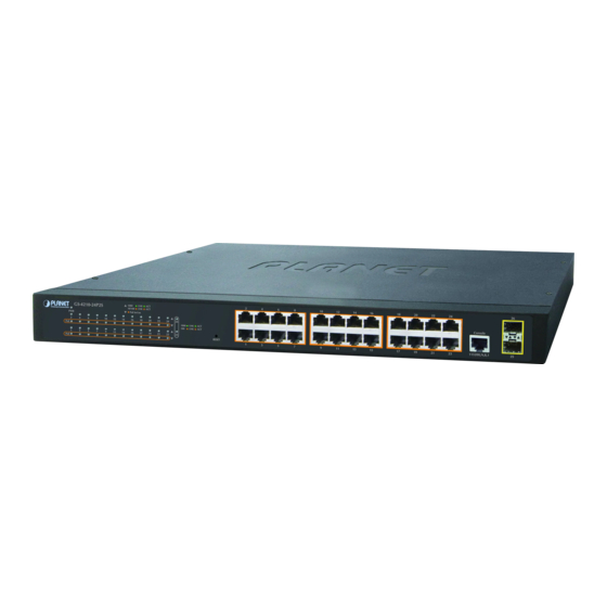
The front panel provides a simple interface monitoring the Managed Switch. Figure 2-1-1, Figure 2-1-2, Figure 2-1-3, Figure 2-1-4 and Figure 2-1-5 show their front panels. Front Panel Figure 2-1-1: GS-4210-16T2S Front Panel Front Panel Figure 2-1-2: GS-4210-24T2S Front Panel Front Panel Figure 2-1-3: GS-4210-48T4S Front Panel... - Page 28 User’s Manual of GS-4210-16T2S_24T2S_16P2S_24P2S_48T4S ■ Gigabit TP Interface 10/100/1000BASE-T Copper, RJ45 twisted-pair: Up to 100 meters. 802.3af/802.3at PoE Injector (GS-4210-16P2S and GS-4210-24P2S) ■ 100/1000BASE-X SFP Slots Each of the SFP (Small Form-factor Pluggable) slot supports dual-speed, 1000BASE-SX/LX or 100BASE-FX For 1000BASE-SX/LX SFP transceiver module: From 550 meters (multi-mode fiber) to 10/20/30/40/50/60/70/120 kilometers (single-mode fiber).
-
Page 29: Led Indications
The front panel LEDs indicate instant status of port links, data activity, PoE status and system power; helps monitor and troubleshoot when needed. Figure 2-1-6, Figure 2-1-7, Figure 2-1-8, Figure 2-1-9 and Figure 2-1-10 show their LED indications. LED Indication Figure 2-1-6: GS-4210-16T2S LED Panel ■ System Color Function Lights to indicate that the Switch has power. - Page 30 User’s Manual of GS-4210-16T2S_24T2S_16P2S_24P2S_48T4S Figure 2-1-7: GS-4210-24T2S LED Panel ■ System Color Function Lights to indicate that the Switch has power. Green 10/100/1000BASE-T Interfaces Color Function To indicate the link through that port is successfully established at 1000Mbps. Lights: 1000 Green To indicate that the switch is actively sending or receiving data over that port.
- Page 31 User’s Manual of GS-4210-16T2S_24T2S_16P2S_24P2S_48T4S ■ 100/1000BASE-X SFP Interfaces Color Function To indicate the link through that port is successfully established at 1000Mbps. Lights: 1000 Green To indicate that the switch is actively sending or receiving data over that port. LNK/ACT Blinks: To indicate the link through that port is successfully established at 100Mbps.
- Page 32 User’s Manual of GS-4210-16T2S_24T2S_16P2S_24P2S_48T4S LED Indication Figure 2-1-10: GS-4210-24P2S LED Panel ■ System Color Function Lights to indicate that the Switch has power. Green ■ 10/100/1000BASE-T Interfaces Color Function To indicate the link through that port is successfully established at 1000Mbps. Lights: 1000 Green...
-
Page 33: Switch Rear Panel
The rear panel of the Managed Switch indicates an AC inlet power socket, which accepts input power from 100 to 240V AC, 50-60Hz. Figure 2-1-11, Figure 2-1-12 and Figure 2-1-13 show their rear panels. Rear Panel Figure 2-1-11: Rear Panel of GS-4210-16T2S/GS-4210-24T2S Rear Panel Figure 2-1-12: Rear Panel of GS-4210-48T4S Rear Panel Figure 2-1-13: Rear Panel of GS-4210-16P2S and GS-4210-24P2S ■... -
Page 34: Installing The Switch
User’s Manual of GS-4210-16T2S_24T2S_16P2S_24P2S_48T4S 2.2 Installing the Switch This section describes how to install your Managed Switch and make connections to the Managed Switch. Please read the following topics and perform the procedures in the order being presented. To install your Managed Switch on a desktop or shelf, simply complete the following steps. -
Page 35: Rack Mounting
User’s Manual of GS-4210-16T2S_24T2S_16P2S_24P2S_48T4S Supplying power to the Managed Switch. Step 5: Connect one end of the power cable to the Managed Switch and the power plug of the power cable to a standard wall outlet. When the Managed Switch receives power, the Power LED should remain solid Green. 2.2.2 Rack Mounting To install the Managed Switch in a 19-inch standard rack, please follow the instructions described below. -
Page 36: Installing The Sfp Transceiver
User’s Manual of GS-4210-16T2S_24T2S_16P2S_24P2S_48T4S Figure 2-1-16: Mounting Managed Switch in a Rack Proceed with Steps 4 and 5 of session 2.2.1 Desktop Installation to connect the network cabling and supply power to the Step 6: Managed Switch. 2.2.3 Installing the SFP transceiver The sections describe how to insert an SFP transceiver into an SFP slot. - Page 37 User’s Manual of GS-4210-16T2S_24T2S_16P2S_24P2S_48T4S Approved PLANET SFP Transceivers PLANET Managed Switch supports both single mode and multi-mode SFP transceiver. The following list of approved PLANET SFP transceivers is correct at the time of publication: Gigabit SFP Transceiver Modules SFP-Port 1000BASE-T Module ...
- Page 38 User’s Manual of GS-4210-16T2S_24T2S_16P2S_24P2S_48T4S Connecting the Fiber Cable Insert the duplex LC connector into the SFP transceiver. Connect the other end of the cable to a device with SFP transceiver installed. Check the LNK/ACT LED of the SFP slot on the front of the Managed Switch. Ensure that the SFP transceiver is operating correctly.
-
Page 39: Switch Management
User’s Manual of GS-4210-16T2S_24T2S_16P2S_24P2S_48T4S 3. SWITCH MANAGEMENT This chapter explains the methods that you can use to configure management access to the Managed Switch. It describes the types of management applications and the communication and management protocols that deliver data between your management device (workstation or personal computer) and the system. -
Page 40: Management Access Overview
User’s Manual of GS-4210-16T2S_24T2S_16P2S_24P2S_48T4S 3.2 Management Access Overview The Managed Switch gives you the flexibility to access and manage it using any or all of the following methods: An administration console Web browser interface An external SNMP-based network management application ... -
Page 41: Administration Console
User’s Manual of GS-4210-16T2S_24T2S_16P2S_24P2S_48T4S 3.3 Administration Console The administration console is an internal, character-oriented, and command line user interface for performing system administration such as displaying statistics or changing option settings. Using this method, you can view the administration console from a terminal, personal computer, Apple Macintosh, or workstation connected to the Managed Switch's console port. There are two ways to use this management method: via direct access or modem port access. -
Page 42: Web Management
Managed Switch's console port. Web Management requires either Microsoft Internet Explorer 8.0 or later, Google Chrome, Safari or Mozilla Firefox 1.5 or later. The following web screen based on GS-4210-24T2S will be the same as that of GS-4210-16T2S, GS-4210-48T4S, GS-4210-16P2S and GS-4210-24P2S. -
Page 43: Snmp-Based Network Management
User’s Manual of GS-4210-16T2S_24T2S_16P2S_24P2S_48T4S Figure 3-4: Web Main Screen of Managed Switch 3.5 SNMP-based Network Management You can use an external SNMP-based application to configure and manage the Managed Switch, such as SNMPc Network Manager, HP Openview Network Node Management (NNM) or What’s Up Gold. This management method requires the SNMP agent on the switch and the SNMP Network Management Station to use the same community string. -
Page 44: Planet Smart Discovery Utility
User’s Manual of GS-4210-16T2S_24T2S_16P2S_24P2S_48T4S 3.6 PLANET Smart Discovery Utility For easily listing the Managed Switch in your Ethernet environment, the Planet Smart Discovery Utility is an ideal solution. The following installation instructions are to guide you to running the Planet Smart Discovery Utility. - Page 45 To click the “Control Packet Force Broadcast” function, it allows you to assign a new setting value to the Web Smart Switch under a different IP subnet address. Press “Connect to Device” button and the input usrname/password in web login screen and the web main screen appears Figure 3-4. Press “Exit” button to shut down the Planet Smart Discovery Utility.
-
Page 46: Web Configuration
User’s Manual of GS-4210-16T2S_24T2S_16P2S_24P2S_48T4S 4. WEB CONFIGURATION This section introduces the configuration and functions of the Web-based management. About Web-based Management The Managed Switch offers management features that allow users to manage the Managed Switch from anywhere on the network through a standard browser such as Microsoft Internet Explorer. The Web-based Management supports Internet Explorer 8.0. - Page 47 Figure 4-1-2: Login Screen Default User name: admin Default Password: admin The following web screen based on GS-4210-24T2S will be the same as that of GS-4210-16T2S, GS-4210-48T4S, GS-4210-16P2S and GS-4210-24P2S. After entering the username and password, the main screen appears as Figure 4-1-3.
- Page 48 User’s Manual of GS-4210-16T2S_24T2S_16P2S_24P2S_48T4S Figure 4-1-3: Web Main Screen of Managed Switch Now, you can use the Web management interface to continue the switch management or manage the Managed Switch by Web interface. The Switch Menu on the left of the web page let you access all the commands and statistics the Managed Switch provides.
-
Page 49: Main Web Page
User’s Manual of GS-4210-16T2S_24T2S_16P2S_24P2S_48T4S 4.1 Main Web Page The Managed Switch provides a Web-based browser interface for configuring and managing it. This interface allows you to access the Managed Switch using the Web browser of your choice. This chapter describes how to use the Managed Switch’s Web browser interface to configure and manage it. - Page 50 User’s Manual of GS-4210-16T2S_24T2S_16P2S_24P2S_48T4S Figure 4-1-5: Managed Switch Main Functions Menu Buttons : Click to save changes or reset to default. : Click to logout the Managed Switch. : Click to reboot the Managed Switch. : Click to refresh the page. The PoE function only available on GS-4210-16P2S and GS-4210-24P2S, the GS-4210 ...
-
Page 51: Save Button
User’s Manual of GS-4210-16T2S_24T2S_16P2S_24P2S_48T4S 4.1.1 Save Button This save button allows to save the running/startup/backup configuration or reset switch in default parameter. The screen in Figure 4-1-6 appears. Figure 4-1-6: Save Button Screenshot The page includes the following fields: Object Description •... -
Page 52: Saving Configuration
User’s Manual of GS-4210-16T2S_24T2S_16P2S_24P2S_48T4S up configuration file, which is called configuration save. To prevent illicit file upload and easier configuration, switch mandates the name of running configuration file to be running-config. Refers to the configuration sequence used in switch startup. Startup •... - Page 53 User’s Manual of GS-4210-16T2S_24T2S_16P2S_24P2S_48T4S Select “Source File = Running Configuration” and “Destination File = Startup Configuration”. Press the “Apply” button to save running configuration to startup configuration.
-
Page 54: System
User’s Manual of GS-4210-16T2S_24T2S_16P2S_24P2S_48T4S 4.2 System Use the System menu items to display and configure basic administrative details of the Managed Switch. Under System the following topics are provided to configure and view the system information: This section has the following items: The switch system information is provided here. -
Page 55: Ip Configuration
User’s Manual of GS-4210-16T2S_24T2S_16P2S_24P2S_48T4S • The IP Address of Managed Switch. IP Address • The subnet mask of Managed Switch. Subnet Mask • Gateway The gateway of Managed Switch. • Loader Version The loader version of Managed Switch. The loader date of Managed Switch. •... - Page 56 User’s Manual of GS-4210-16T2S_24T2S_16P2S_24P2S_48T4S same subnet domain. DHCP: Enable DHCP client mode operation. Enable the DHCP client by checking this box. If DHCP fails and the configured IP address is zero, DHCP will retry. If DHCP fails and the configured IP address is non-zero, DHCP will stop and the configured IP settings will be used.
-
Page 57: Ipv6 Configuration
User’s Manual of GS-4210-16T2S_24T2S_16P2S_24P2S_48T4S 4.2.3 IPv6 Configuration The IPv6 Configuration includes Auto Configuration, IPv6 Address and Gateway. The configured column is used to view or change the IPv6 configuration. Fill out the Auto Configuration, IPv6 Address and Gateway for the device. The screens in Figure 4-2-4 Figure 4-2-5... - Page 58 User’s Manual of GS-4210-16T2S_24T2S_16P2S_24P2S_48T4S Button : Click to apply changes. Figure 4-2-5: IPv6 Information Page Screenshot The page includes the following fields: Object Description • Auto Configuration Display the current auto configuration state. • IPv6 In Use Address Display the current IPv6 in-use address. Display the current in-use gateway.
-
Page 59: User Configuration
User’s Manual of GS-4210-16T2S_24T2S_16P2S_24P2S_48T4S 4.2.4 User Configuration This page provides an overview of the current users and privilege type. Currently the only way to login as another user on the web server is to close and reopen the browser. After setup completed, please press “Apply” button to take effect. Please login web interface with new user name and password as the screens in Figure 4-2-6 Figure 4-2-7... -
Page 60: Time Settings
User’s Manual of GS-4210-16T2S_24T2S_16P2S_24P2S_48T4S The page includes the following fields: Object Description Display the current username. • User Name Display the current password type. • Password Type Display the current privilege type. • Privilege Type • Modify Click to modify the local user entry. : Delete the current user 4.2.5 Time Settings 4.2.5.1 System Time... - Page 61 User’s Manual of GS-4210-16T2S_24T2S_16P2S_24P2S_48T4S The page includes the following fields: Object Description Enabled: Enable SNTP mode operation. • Enable SNTP When enable SNTP mode operation, the agent forward and to transfer SNTP messages between the clients and the server when they are not on the same subnet domain.
- Page 62 User’s Manual of GS-4210-16T2S_24T2S_16P2S_24P2S_48T4S • Non-recurring To • Year - Select the starting Year. • Month - Select the starting month. • Date - Select the starting date. • Hours - Select the starting hour. • Minutes - Select the starting minute. Button : Click to apply changes.
-
Page 63: Sntp Configuration
User’s Manual of GS-4210-16T2S_24T2S_16P2S_24P2S_48T4S 4.2.5.2 SNTP Configuration The SNTP Server Configuration screens in Figure 4-2-10 & Figure 4-2-11 appear. Figure 4-2-10: SNTP Setup Page Screenshot The page includes the following fields: Object Description Type the IP address or domain name of the SNTP/NTP server. •... -
Page 64: Log Management
User’s Manual of GS-4210-16T2S_24T2S_16P2S_24P2S_48T4S 4.2.6 Log Management The Managed Switch log management is provided here. The local logs allow you to configure and limit system messages that are logged to flash or RAM memory. The default is for event levels 0 to 3 to be logged to flash and levels 0 to 6 to be logged to RAM. -
Page 65: Local Logging
User’s Manual of GS-4210-16T2S_24T2S_16P2S_24P2S_48T4S Button : Click to apply changes. Figure 4-2-13: Logging Information Page Screenshot The page includes the following fields: Object Description Display the current logging service status. • Logging Service 4.2.6.2 Local Logging The Managed Switch system local log information is provided here. The local Log screens in Figure 4-2-14 Figure 4-2-15 appear. - Page 66 User’s Manual of GS-4210-16T2S_24T2S_16P2S_24P2S_48T4S Emerg: Emergency level of the system unsable for local log. Alert: Alert level of the immediate action needed for local log. Crit: Critical level of the critical conditions for local log. Error: Error level of the error conditions for local log. ...
-
Page 67: Remote Syslog
User’s Manual of GS-4210-16T2S_24T2S_16P2S_24P2S_48T4S 4.2.6.3 Remote Syslog Configure remote syslog on this page. The Remote Syslog page allows you to configure the logging of messages that are sent to syslog servers or other management stations. You can also limit the event messages sent to only those messages below a specified level. - Page 68 User’s Manual of GS-4210-16T2S_24T2S_16P2S_24P2S_48T4S Crit: Critical level of the critical conditions for local log. Error: Error level of the error conditions for local log. Warning: Warning level of the warning conditions for local log. Notice: Notice level of the normal but significant conditions for local log. ...
-
Page 69: Logging Message
User’s Manual of GS-4210-16T2S_24T2S_16P2S_24P2S_48T4S 4.2.6.4 Logging Message The switch log view is provided here. The Log View screens in Figure 4-2-18, Figure 4-2-19 Figure 4-2-20 appear. Figure 4-2-18: Log Information Select Page Screenshot The page includes the following fields: Object Description The target of the log view entry. - Page 70 User’s Manual of GS-4210-16T2S_24T2S_16P2S_24P2S_48T4S Button : Click to view log. Figure 4-2-19: Logging Information Page Screenshot The page includes the following fields: Object Description Display the current log target. • Target • Severity Display the current log severity. • Category Display the current log category.
-
Page 71: Snmp Management
User’s Manual of GS-4210-16T2S_24T2S_16P2S_24P2S_48T4S 4.2.7 SNMP Management 4.2.7.1 SNMP Overview The Simple Network Management Protocol (SNMP) is an application layer protocol that facilitates the exchange of management information between network devices. It is part of the Transmission Control Protocol/Internet Protocol (TCP/IP) protocol suite. -
Page 72: Snmp Setting
User’s Manual of GS-4210-16T2S_24T2S_16P2S_24P2S_48T4S 4.2.7.2 SNMP Setting Configure SNMP setting on this page. The SNMP System global setting screens in Figure 4-2-21 Figure 4-2-22 appear. Figure 4-2-21: SNMP Global Setting Page Screenshot The page includes the following fields: Object Description Indicates the SNMP mode operation. -
Page 73: Snmp View
User’s Manual of GS-4210-16T2S_24T2S_16P2S_24P2S_48T4S 4.2.7.3 SNMP View Configure SNMPv3 view table on this page. The entry index keys are View Name and OID Subtree. The SNMPv3 View Table Setting screens in Figure 4-2-23 Figure 4-2-24 appear. Figure 4-2-23: SNMPv3 View Table Setting Page Screenshot The page includes the following fields: Object Description... - Page 74 User’s Manual of GS-4210-16T2S_24T2S_16P2S_24P2S_48T4S Button : Click to add a new view entry. Figure 4-2-24: SNMP View Table Status Page Screenshot The page includes the following fields: Object Description Display the current SNMP view name. • View Name Display the current SNMP subtree OID. •...
-
Page 75: Snmp Access Group
User’s Manual of GS-4210-16T2S_24T2S_16P2S_24P2S_48T4S 4.2.7.4 SNMP Access Group Configure SNMPv3 access group on this page. The entry index keys are Group Name, Security Model and Security Level. The SNMPv3 Access Group Setting screens in Figure 4-2-25 Figure 4-2-26 appear. Figure 4-2-25: SNMPv3 Access Group Setting Page Screenshot The page includes the following fields: Object Description... - Page 76 User’s Manual of GS-4210-16T2S_24T2S_16P2S_24P2S_48T4S Button : Click to add a new access entry. Figure 4-2-26: SNMP view Table Status Page Screenshot The page includes the following fields: Object Description • Display the current SNMP access group name. Group Name • Security Model Display the current security model.
-
Page 77: Snmp Community
User’s Manual of GS-4210-16T2S_24T2S_16P2S_24P2S_48T4S 4.2.7.5 SNMP Community Configure SNMP Community on this page. The SNMP Community screens in Figure 4-2-27 Figure 4-2-28 appear. Figure 4-2-27: Community Setting Page Screenshot The page includes the following fields: Object Description Indicates the community read/write access string to permit access to SNMP •... -
Page 78: Snmp User
User’s Manual of GS-4210-16T2S_24T2S_16P2S_24P2S_48T4S Button : Click to add a new community name. Figure 4-2-28: Community Status Page Screenshot The page includes the following fields: Object Description • Community Name Display the current community type. • Group Name Display the current SNMP access group’s name. Display the current view name. - Page 79 User’s Manual of GS-4210-16T2S_24T2S_16P2S_24P2S_48T4S The page includes the following fields: Object Description A string identifying the user name that this entry should belong to. • User Name The allowed string length is 1 to 16. The SNMP Access Group. A string identifying the group name that this entry •...
-
Page 80: Snmpv1, 2 Notification Recipients
User’s Manual of GS-4210-16T2S_24T2S_16P2S_24P2S_48T4S Button : Click to add a new user entry. Figure 4-2-30: SNMPv3 Users Status Page Screenshot The page includes the following fields: Object Description Display the current user name. • User Name Display the current group. •... - Page 81 User’s Manual of GS-4210-16T2S_24T2S_16P2S_24P2S_48T4S The page includes the following fields: Object Description Indicates the SNMP trap destination address. It allows a valid IP address in • Server Address dotted decimal notation ('x.y.z.w'). It can also represent a legally valid IPv4 address.
- Page 82 User’s Manual of GS-4210-16T2S_24T2S_16P2S_24P2S_48T4S • Retry Displays the current retry times. • Action : Delete the SNMPv1, 2 host entry.
-
Page 83: Snmpv3 Notification Recipients
User’s Manual of GS-4210-16T2S_24T2S_16P2S_24P2S_48T4S 4.2.7.8 SNMPv3 Notification Recipients Configure SNMPv3 notification recipients on this page. The SNMPv1, 2 Notification Recipients screens in Figure 4-2-33 and Figure 4-2-34 appear. Figure 4-2-33: SNMPv3 Notification Recipients Page Screenshot The page includes the following fields: Object Description Indicates the SNMP trap destination address. - Page 84 User’s Manual of GS-4210-16T2S_24T2S_16P2S_24P2S_48T4S The page includes the following fields: Object Description Display the current server address. • Server Address Displays the current notify type. • Notify Type • User Name Display the current user name. • UDP Port Display the current UDP port. •...
-
Page 85: Snmp Engine Id
User’s Manual of GS-4210-16T2S_24T2S_16P2S_24P2S_48T4S 4.2.7.9 SNMP Engine ID Configure SNMPv3 Engine ID on this page. The entry index key is Engine ID. The remote engine ID is used to compute the security digest for authenticating and encrypting packets sent to a user on the remote host. The SNMPv3 Engine ID Setting screens in Figure 4-2-35 Figure 4-2-36... -
Page 86: Snmp Remote Engine Id
User’s Manual of GS-4210-16T2S_24T2S_16P2S_24P2S_48T4S 4.2.7.10 SNMP Remote Engine ID Configure SNMPv3 remote Engine ID on this page. The SNMPv3 Remote Engine ID Setting screens in Figure 4-2-37 Figure 4-2-38 appear. Figure 4-2-37: SNMPv3 Remote Engine ID Setting Page Screenshot The page includes the following fields: Object Description Indicates the SNMP remote engine ID address. -
Page 87: Port Management
User’s Manual of GS-4210-16T2S_24T2S_16P2S_24P2S_48T4S 4.3 Port Management Use the Port Menu to display or configure the Managed Switch's ports. This section has the following items: Configures port configuration settings Port Configuration Lists Ethernet and RMON port statistics Port Counters Display current bandwidth utilization ... - Page 88 User’s Manual of GS-4210-16T2S_24T2S_16P2S_24P2S_48T4S Auto - Setup Auto negotiation. Auto-10M - Setup 10M Auto negotiation. Auto-100M - Setup 100M Auto negotiation. Auto-1000M - Setup 1000M Auto negotiation. Auto-10/100M - Setup 10/100M Auto negotiation. 10M - Setup 10M Force mode. ...
- Page 89 User’s Manual of GS-4210-16T2S_24T2S_16P2S_24P2S_48T4S Button : Click to apply changes. Figure 4-3-2: Port Status Page Screenshot...
-
Page 90: Port Counters
User’s Manual of GS-4210-16T2S_24T2S_16P2S_24P2S_48T4S The page includes the following fields: Object Description • This is the logical port number for this row. Port • Description Click to indicate the port name. • Enable State Display the current port state. • Display the current link status. - Page 91 User’s Manual of GS-4210-16T2S_24T2S_16P2S_24P2S_48T4S Figure 4-3-4: Interface Counters Page Screenshot Object Description • ifInOctets The total number of octets received on the interface, including framing characters. (Received Octets) • ifInUcastPkts The number of subnetwork-unicast packets delivered to a higher-layer protocol. (Received Unicast Packets) The number of packets received via the interfaces which were discarded...
- Page 92 User’s Manual of GS-4210-16T2S_24T2S_16P2S_24P2S_48T4S • ifOutDiscards The number of inbound packets which were chosen to be discarded even though no errors had been detected to prevent their being deliverable to ahigher-layer (Transmit Discards protocol. One possible reason for discarding such a packet could be to free up Packets) buffer space.
- Page 93 User’s Manual of GS-4210-16T2S_24T2S_16P2S_24P2S_48T4S Object Description • dot3StatsAlignmentErrors The number of alignment errors (missynchronized data packets). A count of frames received on a particular interface that are an integral • dot3StatsFCSErrors number of octets in length but do not pass the FCS check. This count does not include frames received with frame-too-long or frame-too-short error.
- Page 94 User’s Manual of GS-4210-16T2S_24T2S_16P2S_24P2S_48T4S Figure 4-3-6: RMON Counters Page Screenshot Object Description • etherStatsDropEvents The total number of events in which packets were dropped due to lack of resources. • etherStatsOctets The total number of octets received and transmitted on the interface, including framing characters.
- Page 95 User’s Manual of GS-4210-16T2S_24T2S_16P2S_24P2S_48T4S • etherStatsJabbers The total number of frames received that were longer than 1518 octets (excluding framing bits, but including FCS octets), and had either an FCS or alignment error. The best estimate of the total number of collisions on this Ethernet •...
-
Page 96: Bandwidth Utilization
User’s Manual of GS-4210-16T2S_24T2S_16P2S_24P2S_48T4S 4.3.3 Bandwidth Utilization The Bandwidth Utilization page displays the percentage of the total available bandwidth being used on the ports. Bandwith utilization statistics can be viewed using a line graph. The Bandwidth Utilization screen in Figure 4-3-7 appears. -
Page 97: Port Mirroring
User’s Manual of GS-4210-16T2S_24T2S_16P2S_24P2S_48T4S 4.3.4 Port Mirroring Configure port Mirroring on this page. This function provide to monitoring network traffic that forwards a copy of each incoming or outgoing packet from one port of a network Switch to another port where the packet can be studied. It enables the manager to keep close track of switch performance and alter it if necessary. - Page 98 User’s Manual of GS-4210-16T2S_24T2S_16P2S_24P2S_48T4S Mirror Port Configuration The Port Mirror Configuration screens in Figure 4-3-9 Figure 4-3-10 appear. Figure 4-3-9: Port Mirroring Settings Page Screenshot The page includes the following fields: Object Description • Session ID Set the port mirror session ID. Possible ID are: 1 to 4. •...
- Page 99 User’s Manual of GS-4210-16T2S_24T2S_16P2S_24P2S_48T4S Button : Click to apply changes. Figure 4-3-10: Mirroring Status Page Screenshot The page includes the following fields: Object Description Display the session ID. • Session ID • Destination Port This is the mirroring port entry. •...
-
Page 100: Jumbo Frame
User’s Manual of GS-4210-16T2S_24T2S_16P2S_24P2S_48T4S 4.3.5 Jumbo Frame This page provides to select the maximum frame size allowed for the switch port. The Jumbo Frame screens in Figure 4-3-11 Figure 4-3-12 appear. Figure 4-3-11: Jumbo Frame Setting Page Screenshot The page includes the following fields: Object Description Enter the maximum frame size allowed for the switch port, including FCS. -
Page 101: Port Error Disabled Configuration
User’s Manual of GS-4210-16T2S_24T2S_16P2S_24P2S_48T4S 4.3.6 Port Error Disabled Configuration This page provides to set port error disable function. The Port Error Disable Configuration screens in Figure 4-3-13 Figure 4-3-14 appear. Figure 4-3-13: Error Disabled Recovery Page Screenshot The page includes the following fields: Object Description The period (in seconds) for which a port will be kept disabled in the event of a port... - Page 102 User’s Manual of GS-4210-16T2S_24T2S_16P2S_24P2S_48T4S • DHCP Rate Limit Enable or disable the port error disabled function to check status by DHCP rate limit • Enable or disable the port error disabled function to check status by ARP rate limit ARP Rate Limt Button : Click to apply changes.
-
Page 103: Port Error Disabled Status
User’s Manual of GS-4210-16T2S_24T2S_16P2S_24P2S_48T4S 4.3.7 Port Error Disabled Status This page provides disable that transitions a port into error disable and the recovery options. The ports were disabled by some protocols such as BPDU Guard, Loopback and UDLD. The Port Error Disable screen in Figure 4-3-15 appears. -
Page 104: Protected Ports
User’s Manual of GS-4210-16T2S_24T2S_16P2S_24P2S_48T4S 4.3.8 Protected Ports Overview When a switch port is configured to be a member of protected group (also called Private VLAN), communication between protected ports within that group can be prevented. Two application examples are provided in this section: •... - Page 105 User’s Manual of GS-4210-16T2S_24T2S_16P2S_24P2S_48T4S The configuration of promiscuous and isolated ports applies to all private VLANs. When traffic comes in on a promiscuous port in a private VLAN, the VLAN mask from the VLAN table is applied. When traffic comes in on an isolated port, the private VLAN mask is applied in addition to the VLAN mask from the VLAN table.
- Page 106 User’s Manual of GS-4210-16T2S_24T2S_16P2S_24P2S_48T4S Button : Click to apply changes. Figure 4-3-17: Protect Ports Status Page Screenshot The page includes the following fields: Object Description • Protected Ports Display the current protected ports. • Unprotected Ports Display the current unprotected ports.
-
Page 107: Eee
User’s Manual of GS-4210-16T2S_24T2S_16P2S_24P2S_48T4S 4.3.9 EEE What is EEE EEE is a power saving option that reduces the power usage when there is low or no traffic utilization. EEE works by powering down circuits when there is no traffic. When a port gets data to be transmitted all circuits are powered up. The time it takes to power up the circuits is named wakeup time. - Page 108 User’s Manual of GS-4210-16T2S_24T2S_16P2S_24P2S_48T4S Button : Click to apply changes. Figure 4-3-19: EEE Enable Status Page Screenshot...
- Page 109 User’s Manual of GS-4210-16T2S_24T2S_16P2S_24P2S_48T4S The page includes the following fields: Object Description The switch port number of the logical port. • Port Display the current EEE state. • EEE State...
-
Page 110: Link Aggregation
User’s Manual of GS-4210-16T2S_24T2S_16P2S_24P2S_48T4S 4.4 Link Aggregation Port Aggregation optimizes port usage by linking a group of ports together to form a single Link Aggregated Groups (LAGs). Port Aggregation multiplies the bandwidth between the devices, increases port flexibility, and provides link redundancy. Each LAG is composed of ports of the same speed, set to full-duplex operations. - Page 111 User’s Manual of GS-4210-16T2S_24T2S_16P2S_24P2S_48T4S The Link Aggregation Control Protocol (LACP) provides a standardized means for exchanging information between Partner Systems that require high speed redundant links. Link aggregation lets you group up to eight consecutive ports into a single dedicated connection. This feature can expand bandwidth to a device on the network. LACP operation requires full-duplex mode, more detail information refer to the IEEE 802.3ad standard.
-
Page 112: Lag Setting
User’s Manual of GS-4210-16T2S_24T2S_16P2S_24P2S_48T4S 4.4.1 LAG Setting This page allows configuring load balance algorithm configuration settings. The LAG Setting screens in Figure 4-4-2 Figure 4-4-3 appear. Figure 4-4-2: LAG Setting Page Screenshot The page includes the following fields: Object Description Select load balance algorithm mode: •... -
Page 113: Lag Managment
User’s Manual of GS-4210-16T2S_24T2S_16P2S_24P2S_48T4S 4.4.2 LAG Managment This page is used to configure the LAG management. The LAG Management screens in Figure 4-4-4 Figure 4-4-5 appear. Figure 4-4-4: LAG Management Page Screenshot The page includes the following fields: Object Description Select LAG number for this drop down list, the available range is 1 to 8. -
Page 114: Lag Port Setting
User’s Manual of GS-4210-16T2S_24T2S_16P2S_24P2S_48T4S The page includes the following fields: Object Description The LAG for the settings contained in the same row. • Display the current name. • Name • Type Display the current type. • Link State Display the link state. •... - Page 115 User’s Manual of GS-4210-16T2S_24T2S_16P2S_24P2S_48T4S Auto-1000M - Setup 1000M Auto negotiation. Auto-10/100M - Setup 10/100M Auto negotiation. 10M - Setup 10M Force mode. 100M - Setup 100M Force mode. 1000M - Setup 1000M Force mode. When Auto Speed is selected for a port, this section indicates the flow control •...
-
Page 116: Lacp Setting
User’s Manual of GS-4210-16T2S_24T2S_16P2S_24P2S_48T4S • Enable State Display the current enable state. • Link Status Display the link status of per LAG group. • Speed Display the current speed. • Duplex Display the current duplex mode. Display the current flow control configuration. •... -
Page 117: Lacp Port Setting
User’s Manual of GS-4210-16T2S_24T2S_16P2S_24P2S_48T4S Button : Click to apply changes. Figure 4-4-9: LACP Information Page Screenshot The page includes the following fields: Object Description Display the current LACP disable/enable status. • State Display the current system priority. • System Priority 4.4.5 LACP Port Setting This page is used to configure the LACP port setting. - Page 118 User’s Manual of GS-4210-16T2S_24T2S_16P2S_24P2S_48T4S Lower number means greater priority. • The Timeout controls the period between BPDU transmissions. Timeout Short will transmit LACP packets each second, while Long will wait for 30 seconds before sending a LACP packet. Button : Click to apply changes. Figure 4-4-11: LACP Port Information Page Screenshot The page includes the following fields: Object...
-
Page 119: Lag Status
User’s Manual of GS-4210-16T2S_24T2S_16P2S_24P2S_48T4S 4.4.6 LAG Status This page displays LAG status. The LAG Status screens in Figure 4-4-12 Figure 4-4-13 appear. Figure 4-4-12: LAG Status Page Screenshot The page includes the following fields: Object Description Display the current trunk entry. •... - Page 120 User’s Manual of GS-4210-16T2S_24T2S_16P2S_24P2S_48T4S • AtKey Port key of actor. The key is designed to be the same as trunk ID. • Sel LACP selection logic status of the port. “S” means selected “U” means unselected “D” means standby •...
-
Page 121: Vlan
User’s Manual of GS-4210-16T2S_24T2S_16P2S_24P2S_48T4S 4.5 VLAN 4.5.1 VLAN Overview A Virtual Local Area Network (VLAN) is a network topology configured according to a logical scheme rather than the physical layout. VLAN can be used to combine any collection of LAN segments into an autonomous user group that appears as a single LAN. -
Page 122: Ieee 802.1Q Vlan
User’s Manual of GS-4210-16T2S_24T2S_16P2S_24P2S_48T4S This section has the following items: Configures the management VLAN. Management VLAN Creates thn VLAN group. Create VLAN Configures mode and PVID on the VLAN port. Interface Settings Configures the VLAN membership. Port to VLAN Display the VLAN membership. - Page 123 User’s Manual of GS-4210-16T2S_24T2S_16P2S_24P2S_48T4S VLAN can also provide a level of security to your network. IEEE 802.1Q VLAN will only deliver packets between stations that are members of the VLAN. Any port can be configured as either tagging or untagging.: ...
- Page 124 User’s Manual of GS-4210-16T2S_24T2S_16P2S_24P2S_48T4S Adding an IEEE802.1Q Tag Dest. Addr. Src. Addr. Length/E. type Data Old CRC Original Ethernet New Tagged Packet Dest. Addr. Src. Addr. E. type Length/E. type Data New CRC Priority VLAN ID ■ Port VLAN ID Packets that are tagged (are carrying the 802.1Q VID information) can be transmitted from one 802.1Q compliant network device to another with the VLAN information intact.
-
Page 125: Management Vlan
User’s Manual of GS-4210-16T2S_24T2S_16P2S_24P2S_48T4S dynamically using GVRP. However, if you want a port on this switch to participate in one or more VLANs, but none of the intermediate network devices nor the host at the other end of the connection supports VLANs, then you should add this port to the VLAN as an untagged port. -
Page 126: Create Vlan
User’s Manual of GS-4210-16T2S_24T2S_16P2S_24P2S_48T4S Button : Click to apply changes. Figure 4-5-2: Management VLAN State Page Screenshot The page includes the following fields: Object Description Display the current management VLAN. • Management VLAN 4.5.4 Create VLAN Create/delete VLAN on this page. The screens in Figure 4-5-3 Figure 4-5-4 appear. -
Page 127: Interface Settings
User’s Manual of GS-4210-16T2S_24T2S_16P2S_24P2S_48T4S Button : Click to apply changes. Figure 4-5-4: VLAN Table Page Screenshot The page includes the following fields: Object Description Display the current VLAN ID entry. • VLAN ID • VLAN Name Display the current VLAN ID name. •... - Page 128 User’s Manual of GS-4210-16T2S_24T2S_16P2S_24P2S_48T4S information. (Remember that the PVID is only used internally within the Switch). Untagging is used to send packets from an 802.1Q-compliant network device to a non-compliant network device. Frame Income Income Frame is tagged Income Frame is untagged Frame Leave Leave port is tagged Frame remains tagged...
- Page 129 User’s Manual of GS-4210-16T2S_24T2S_16P2S_24P2S_48T4S This provides a tunneling mechanism to connect remote costumer VLANs through a common MAN space without interfering with the VLAN tags. All tags use EtherType 0x8100 or 0x88A8, where 0x8100 is used for customer tags and 0x88A8 are used for service provider tags.
- Page 130 User’s Manual of GS-4210-16T2S_24T2S_16P2S_24P2S_48T4S By default, the field is set to All. • Ingress Filtering • If ingress filtering is enabled (checkbox is checked), frames classified to a VLAN that the port is not a member of get discarded. • If ingress filtering is disabled, frames classified to a VLAN that the port is not a member of are accepted and forwarded to the switch engine.
- Page 131 User’s Manual of GS-4210-16T2S_24T2S_16P2S_24P2S_48T4S The page includes the following fields: Object Description The switch port number of the logical port. • Port Display the current interface VLAN mode. • Interface VLAN Mode • PVID Display the current PVID. • Accepted Frame Type Display the current access frame type.
-
Page 132: Port To Vlan
User’s Manual of GS-4210-16T2S_24T2S_16P2S_24P2S_48T4S 4.5.6 Port to VLAN Use the VLAN Static Table to configure port members for the selected VLAN index. This Page allows for adding and deleting port members of each VLAN. The screen in Figure 4-5-7 appears. Figure 4-5-7: Port to VLAN Setting Page Screenshot... - Page 133 User’s Manual of GS-4210-16T2S_24T2S_16P2S_24P2S_48T4S The page includes the following fields: Object Description Select VLAN ID for this drop down list to assign VLAN membership. • VLAN ID The switch port number of the logical port. • Port • Interface VLAN Mode Display the current interface VLAN mode.
-
Page 134: Port Vlan Membership
User’s Manual of GS-4210-16T2S_24T2S_16P2S_24P2S_48T4S 4.5.7 Port VLAN Membership This Page provides an overview of membership status for VLAN users. The VLAN Membership Status screen in Figure 4-5-8 appears. Figure 4-5-8: Port VLAN Membership Table Page Screenshot... -
Page 135: Protocol Vlan Group Setting
User’s Manual of GS-4210-16T2S_24T2S_16P2S_24P2S_48T4S The page includes the following fields: Object Description The switch port number of the logical port. • Port Display the current VLAN mode. • Mode • Administrative VLANs Display the current administrative VLANs. • Operational VLANs Display the current operational VLANs. - Page 136 User’s Manual of GS-4210-16T2S_24T2S_16P2S_24P2S_48T4S The page includes the following fields: Object Description Protocol Group ID assigned to the Special Protocol VLAN Group. • Group ID Frame Type can have one of the following values: • Frame Type Ethernet II ...
-
Page 137: Protocol Vlan Port Setting
User’s Manual of GS-4210-16T2S_24T2S_16P2S_24P2S_48T4S 4.5.9 Protocol VLAN Port Setting This Page allows you to map a already configured Group Name to a VLAN/port for the switch. The Protocol VLAN Port Setting/State screens in Figure 4-5-11 Figure 4-5-12 appear. Figure 4-5-11: Protocol VLAN Port Setting Page Screenshot The page includes the following fields: Object Description... -
Page 138: Gvrp Setting
User’s Manual of GS-4210-16T2S_24T2S_16P2S_24P2S_48T4S 4.5.10 GVRP Setting GARP VLAN Registration Protocol (GVRP) defines a way for switches to exchange VLAN information in order to register VLAN members on ports across the network. VLANs are dynamically configured based on join messages issued by host devices and propagated throughout the network. GVRP must be enabled to permit automatic VLAN registration, and to support VLANs which extend beyond the local switch. - Page 139 User’s Manual of GS-4210-16T2S_24T2S_16P2S_24P2S_48T4S The page includes the following fields: Object Description Controls whether GVRP is enabled or disabled on this Managed Switch. • GVRP Button : Click to apply changes. Figure 4-5-14: GVRP Information Page Screenshot The page includes the following fields: Object Description •...
-
Page 140: Gvrp Port Setting
User’s Manual of GS-4210-16T2S_24T2S_16P2S_24P2S_48T4S 4.5.11 GVRP Port Setting The GVRP Port Setting/Status screens in Figure 4-5-15 Figure 4-5-16 appear. Figure 4-5-15: GVRP Global Setting Page Screenshot The page includes the following fields: Object Description Select port for this drop down list to assign protocol VLAN port •... -
Page 141: Gvrp Vlan
User’s Manual of GS-4210-16T2S_24T2S_16P2S_24P2S_48T4S Figure 4-5-16: GVRP Port Status Page Screenshot The page includes the following fields: Object Description The switch port number of the logical port. • Port Display the current GVRP port state. • Enable State Display the current registration mode. •... -
Page 142: Gvrp Statistics
User’s Manual of GS-4210-16T2S_24T2S_16P2S_24P2S_48T4S The page includes the following fields: Object Description Display the current VLAN ID. • VLAN ID Display the current member ports. • Member Ports • Dynamic Ports Display the current dynamic ports. • VLAN Type Display the current VLAN type. 4.5.13 GVRP Statistics The GVRP Port Statistics and Error Statistics screens in Figure 4-5-18... - Page 143 User’s Manual of GS-4210-16T2S_24T2S_16P2S_24P2S_48T4S Figure 4-5-19: GVRP Port Error Statistics Page Screenshot The page includes the following fields: Object Description The switch port number of the logical port. • Port Display the current invalid protocol ID. • Invalid Protocol ID Display the current invalid attribute type.
-
Page 144: Vlan Setting Example
User’s Manual of GS-4210-16T2S_24T2S_16P2S_24P2S_48T4S 4.5.14 VLAN setting example: - Separate VLANs - 802.1Q VLAN Trunk 4.5.14.1 Two separate 802.1Q VLANs The diagram shows how the Managed Switch handle Tagged and Untagged traffic flow for two VLANs. VLAN Group 2 and VLAN Group 3 are separated VLANs. - Page 145 User’s Manual of GS-4210-16T2S_24T2S_16P2S_24P2S_48T4S The scenario described as follows: Untagged packet entering VLAN 2 While [PC-1] transmit an untagged packet enters Port-1, the Managed Switch will tag it with a VLAN Tag=2. [PC-2] and [PC-3] will received the packet through Port-2 and Port-3. [PC-4],[PC-5] and [PC-6] received no packet.
- Page 146 User’s Manual of GS-4210-16T2S_24T2S_16P2S_24P2S_48T4S Assign VLAN mode and PVID for each port: Port-1,Port-2 and Port-3 : VLAN Mode = Hybrid, PVID=2 Port-4,Port-5 and Port-6 : VLAN Mode = Hybrid, PVID=3 Assign Tagged/Untagged for each port: VLAN ID = 2: Port-1 & 2 = Untagged, Port-3 = Tagged, Port -4~6 = Excluded.
-
Page 147: Vlan Trunking Between Two 802.1Q Aware Switch
User’s Manual of GS-4210-16T2S_24T2S_16P2S_24P2S_48T4S 4.5.14.2 VLAN Trunking between two 802.1Q aware switch The most cases are used for “Uplink” to other switches. VLANs are separated at different switches, but they need to access with other switches within the same VLAN group. The screen in Figure 4-5-21 appears. - Page 148 User’s Manual of GS-4210-16T2S_24T2S_16P2S_24P2S_48T4S Setup steps Create VLAN Group 2 and 3 Add VLAN group 2 and group 3 Assign VLAN mode and PVID for each port: Port-1,Port-2 and Port-3 : VLAN Mode = Hybrid, PVID=2 Port-4,Port-5 and Port-6 : VLAN Mode = Hybrid, PVID=3 Port-7 : VLAN Mode = Hybrid, PVID=1 Assign Tagged/Untagged for each port: VLAN ID = 1:...
- Page 149 User’s Manual of GS-4210-16T2S_24T2S_16P2S_24P2S_48T4S VLAN ID = 2: Port-1 & 2 = Untagged, Port-3 & 7 = Tagged, Port -4~6 = Excluded. VLAN ID = 3: Port-4 & 5 = Untagged, Port -6 & 7= Tagged, Port-1~3 = Excluded.
- Page 150 User’s Manual of GS-4210-16T2S_24T2S_16P2S_24P2S_48T4S...
-
Page 151: Spanning Tree Protocol
User’s Manual of GS-4210-16T2S_24T2S_16P2S_24P2S_48T4S 4.6 Spanning Tree Protocol 4.6.1 Theory The Spanning Tree Protocol can be used to detect and disable network loops, and to provide backup links between switches, bridges or routers. This allows the switch to interact with other bridging devices in your network to ensure that only one route exists between any two stations on the network, and provide backup links which automatically take over when a primary link goes down. - Page 152 User’s Manual of GS-4210-16T2S_24T2S_16P2S_24P2S_48T4S The port identifier of the transmitting port The switch sends BPDUs to communicate and construct the spanning-tree topology. All switches connected to the LAN on which the packet is transmitted will receive the BPDU. BPDUs are not directly forwarded by the switch, but the receiving switch uses the information in the frame to calculate a BPDU, and, if the topology changes, initiates a BPDU transmission.
- Page 153 User’s Manual of GS-4210-16T2S_24T2S_16P2S_24P2S_48T4S From disabled to blocking Figure 4-6-1: STP Port State Transitions You can modify each port state by using management software. When you enable STP, every port on every switch in the network goes through the blocking state and then transitions through the states of listening and learning at power up. If properly configured, each port stabilizes to the forwarding or blocking state.
- Page 154 User’s Manual of GS-4210-16T2S_24T2S_16P2S_24P2S_48T4S The Bridge Identifier consists of two parts: except by setting priority a 16-bit priority and a 48-bit Ethernet MAC below) address 32768 + MAC A relative priority for each switch – lower 32768 Priority numbers give a higher priority and a greater chance of a given switch being elected as the root bridge The length of time between broadcasts of...
- Page 155 User’s Manual of GS-4210-16T2S_24T2S_16P2S_24P2S_48T4S Hello Time – The Hello Time can be from 1 to 10 seconds. This is the interval between two transmissions of BPDU packets sent by the Root Bridge to tell all other Switches that it is indeed the Root Bridge. If you set a Hello Time for your Switch, and it is not the Root Bridge, the set Hello Time will be used if and when your Switch becomes the Root Bridge.
- Page 156 User’s Manual of GS-4210-16T2S_24T2S_16P2S_24P2S_48T4S Figure 4-6-2: Before Applying the STA Rules In this example, only the default STP values are used. Figure 4-6-3: After Applying the STA Rules...
-
Page 157: Stp Global Settings
User’s Manual of GS-4210-16T2S_24T2S_16P2S_24P2S_48T4S The switch with the lowest Bridge ID (switch C) was elected the root bridge, and the ports were selected to give a high port cost between switches B and C. The two (optional) Gigabit ports (default port cost = 20,000) on switch A are connected to one (optional) Gigabit port on both switch B and C. - Page 158 User’s Manual of GS-4210-16T2S_24T2S_16P2S_24P2S_48T4S The page includes the following fields: Object Description Enable or disable the STP function. The default value is "Disabled". • Enable Set the BPDU forward method. • BPDU Forward • PathCost Method The path cost method is used to determine the best path between devices. Therefore, lower values should be assigned to ports attached to faster media, and higher values assigned to ports with slower media.
-
Page 159: Stp Port Setting
User’s Manual of GS-4210-16T2S_24T2S_16P2S_24P2S_48T4S 4.6.3 STP Port Setting This page allows you to configure per port STP settings. The STP Port Setting screens in Figure 4-6-6 Figure 4-6-7 appear. Figure 4-6-6 : STP Port Configuration Page Screenshot The page includes the following fields: Object Description Select port number for this drop down list. - Page 160 User’s Manual of GS-4210-16T2S_24T2S_16P2S_24P2S_48T4S Button : Click to apply changes. By default, the system automatically detects the speed and duplex mode used on each port, and configures the path cost according to the values shown below. Path cost “0” is used to indicate auto-configuration mode. When the short path cost method is selected and the default path cost recommended by the IEEE 8021w standard exceeds 65,535, the default is set to 65,535.
- Page 161 User’s Manual of GS-4210-16T2S_24T2S_16P2S_24P2S_48T4S Figure 4-6-7: STP Port Status Page Screenshot The page includes the following fields: Object Description • The switch port number of the logical STP port. Port • Admin Enable Display the current STP port mode status. •...
-
Page 162: Cist Instance Setting
User’s Manual of GS-4210-16T2S_24T2S_16P2S_24P2S_48T4S • Display the current BPDU filter configuration. BPDU Filter • BPDU Guard Display the current BPDU guard configuration. • P2P MAC Display the current P2P MAC status. 4.6.4 CIST Instance Setting This Page allows you to configure CIST instance settings. The CIST Instance Setting and Information screens in Figure 4-6-8, Figure 4-6-9... - Page 163 User’s Manual of GS-4210-16T2S_24T2S_16P2S_24P2S_48T4S seconds -Default: -Minimum: The higher of 4 or [(Max. Message Age/2) + 1] -Maximum: The maximum age of the information transmitted by the Bridge when it is the • Max Age Root Bridge. Valid values are in the range 6 to 40 seconds. -Default: -Minimum: The higher of 6 or [2 x (Hello Time + 1)].
- Page 164 User’s Manual of GS-4210-16T2S_24T2S_16P2S_24P2S_48T4S • Display the current Max. age. Max Age • Display the current Tx hold count. Tx Hold Count • Hello Time Display the current hello time. Figure 4-6-10: CIST Instance Information Page Screenshot The page includes the following fields: Object Description •...
-
Page 165: Cist Port Setting
User’s Manual of GS-4210-16T2S_24T2S_16P2S_24P2S_48T4S 4.6.5 CIST Port Setting This page allows you to configure per port CIST priority and cost. The CIST Port Setting and Status screens in Figure 4-6-11 Figure 4-6-12 appear. Figure 4-6-11: CIST Port Setting Page Screenshot The page includes the following fields: Object Description... - Page 166 User’s Manual of GS-4210-16T2S_24T2S_16P2S_24P2S_48T4S Button : Click to apply changes. Figure 4-6-12: CIST Port Status Page Screenshot...
- Page 167 User’s Manual of GS-4210-16T2S_24T2S_16P2S_24P2S_48T4S The page includes the following fields: Object Description The switch port number of the logical STP port. • Port • Indentifier Display the current indentifier (Priority/Port ID). (Priority/Port ID) • External Path Cost Display the current external path cost conf/oper. Conf/Oper •...
-
Page 168: Mst Instance Configuration
User’s Manual of GS-4210-16T2S_24T2S_16P2S_24P2S_48T4S 4.6.6 MST Instance Configuration This page allows the user to configure MST Instance Configuration. The MST Instance Setting, Information and Status screens Figure 4-6-13, Figure 4-6-14 Figure 4-6-15 appear. Figure 4-6-13: MST Instance Setting Page Screenshot The page includes the following fields: Object Description... - Page 169 User’s Manual of GS-4210-16T2S_24T2S_16P2S_24P2S_48T4S Figure 4-6-15: MST Instance Status Page Screenshot The page includes the following fields: Object Description Display the MSTI ID. • MSTI ID Display the current designated root bridge. • Regional Root Bridge Display the current internal root cost. •...
-
Page 170: Mst Port Setting
User’s Manual of GS-4210-16T2S_24T2S_16P2S_24P2S_48T4S 4.6.7 MST Port Setting This page allows the user to inspect the current STP MSTI port configurations, and possibly change them as well. A MSTI port is a virtual port, which is instantiated separately for each active CIST (physical) port for each MSTI instance configured and applicable for the port. - Page 171 User’s Manual of GS-4210-16T2S_24T2S_16P2S_24P2S_48T4S Figure 4-6-17: MST Port Status Page Screenshot The page includes the following fields: Object Description • MSTI ID Display the current MSTI ID. • Port The switch port number of the logical STP port. • Indentifier Display the current indentifier (priority/port ID).
-
Page 172: Stp Statistics
User’s Manual of GS-4210-16T2S_24T2S_16P2S_24P2S_48T4S 4.6.8 STP Statistics This page displays STP statistics. The STP statistics screen in Figure 4-6-18 appears. Figure 4-6-18: STP Statistics Page Screenshot... - Page 173 User’s Manual of GS-4210-16T2S_24T2S_16P2S_24P2S_48T4S The page includes the following fields: Object Description The switch port number of the logical STP port. • Port • Configuration BPDUs Display the current configuration BPDUs received. Received Display the current TCN BPDUs received. • TCN BPDUs Received •...
-
Page 174: Multicast
User’s Manual of GS-4210-16T2S_24T2S_16P2S_24P2S_48T4S 4.7 Multicast This section has the following items: Configures multicast properties. Properties Configures IGMP snooping settings. IGMP Snooping Display the IGMP snooping statistics. IGMP Snooping Statistics Configures MLD snooping settings. MLD Snooping Display the MLD snooping statistics. - Page 175 User’s Manual of GS-4210-16T2S_24T2S_16P2S_24P2S_48T4S Options are: MAC or Src-Dst-Ip. • IPv6 Forward Method Configure the IPv6 multicast fordward method. Options are: MAC or Src-Dst-Ip. Button : Click to apply changes. Figure 4-7-2: Properties Information Page Screenshot The page includes the following fields: Object Description •...
-
Page 176: Igmp Snooping
User’s Manual of GS-4210-16T2S_24T2S_16P2S_24P2S_48T4S 4.7.2 IGMP Snooping The Internet Group Management Protocol (IGMP) lets host and routers share information about multicast groups memberships. IGMP snooping is a switch feature that monitors the exchange of IGMP messages and copies them to the CPU for feature processing. - Page 177 User’s Manual of GS-4210-16T2S_24T2S_16P2S_24P2S_48T4S Figure 4-7-4: Multicast Flooding Figure 4-7-5: IGMP Snooping Multicast Stream Control...
- Page 178 User’s Manual of GS-4210-16T2S_24T2S_16P2S_24P2S_48T4S IGMP Versions 1 and 2 Multicast groups allow members to join or leave at any time. IGMP provides the method for members and multicast routers to communicate when joining or leaving a multicast group. IGMP version 1 is defined in RFC 1112. It has a fixed packet size and no optional data. The format of an IGMP packet is shown below: IGMP Message Format Octets...
- Page 179 User’s Manual of GS-4210-16T2S_24T2S_16P2S_24P2S_48T4S The states a computer will go through to join or to leave a multicast group are shown below: Figure 4-7-6: IGMP State Transitions IGMP Querier – A router, or multicast-enabled switch, can periodically ask their hosts if they want to receive multicast traffic. If there is more than one router/switch on the LAN performing IP multicasting, one of these devices is elected “querier”...
-
Page 180: Igmp Setting
User’s Manual of GS-4210-16T2S_24T2S_16P2S_24P2S_48T4S 4.7.2.1 IGMP Setting This page provides IGMP Snooping related configuration. Most of the settings are global, whereas the Router Port configuration is related to the current unit, as reflected by the page header. The IGMP Snooping Setting and Information screens in Figure 4-7-7, Figure 4-7-8... - Page 181 User’s Manual of GS-4210-16T2S_24T2S_16P2S_24P2S_48T4S The page includes the following fields: Object Description Dipaly the current IGMP snooping status. • IGMP Snooping Status Display the current IGMP snooping version. • IGMP Snooping Version • IGMP Snooping V2 Report Display the current IGMP snooping v2 report suppression. Suppression Figure 4-7-9: IGMP Snooping Information Page Screenshot The page includes the following fields:...
-
Page 182: Igmp Querier Setting
User’s Manual of GS-4210-16T2S_24T2S_16P2S_24P2S_48T4S 4.7.2.2 IGMP Querier Setting This page provides IGMP Querier Setting. The IGMP Querier Setting screens in Figure 4-7-10 Figure 4-7-11 appear. Figure 4-7-10: IGMP VLAN Setting Page Screenshot The page includes the following fields: Object Description Select VLAN ID for this drop down list. -
Page 183: Igmp Static Group
User’s Manual of GS-4210-16T2S_24T2S_16P2S_24P2S_48T4S • Querier Status Display the current querier stauts. • Querier Version Display the current querier version. Display the current querier IP. • Querier IP 4.7.2.3 IGMP Static Group Multicast filtering can be dynamically configured using IGMP Snooping and IGMP Query messages as described in above sections. -
Page 184: Igmp Group Table
User’s Manual of GS-4210-16T2S_24T2S_16P2S_24P2S_48T4S Figure 4-7-13: IGMP Static Groups Page Screenshot The page includes the following fields: Object Description • VLAN ID Display the current VLAN ID. • Group IP Address Display the current group IP address. • Member Ports Display the current member ports. -
Page 185: Igmp Router Setting
User’s Manual of GS-4210-16T2S_24T2S_16P2S_24P2S_48T4S 4.7.2.5 IGMP Router Setting Depending on your network connections, IGMP snooping may not always be able to locate the IGMP querier. Therefore, if the IGMP querier is a known multicast router/ switch connected over the network to an interface (port or trunk) on your Managed Switch, you can manually configure the interface (and a specified VLAN) to join all the current multicast groups supported by the attached router. -
Page 186: Igmp Router Table
User’s Manual of GS-4210-16T2S_24T2S_16P2S_24P2S_48T4S The page includes the following fields: Object Description Display the current VLAN ID. • VLAN ID Display the current static ports. • Static Ports • Forbidden Ports Display the current forbidden ports. • Modify Click to edit parameter. Click to delete the group ID entry. - Page 187 User’s Manual of GS-4210-16T2S_24T2S_16P2S_24P2S_48T4S Figure 4-7-18: Static Router Table Page Screenshot The page includes the following fields: Object Description • Display the current VLAN ID. VLAN ID • Port Mask Display the current port mask. Figure 4-7-19: Forbidden Router Table Page Screenshot The page includes the following fields: Object Description...
-
Page 188: Igmp Forward All
User’s Manual of GS-4210-16T2S_24T2S_16P2S_24P2S_48T4S 4.7.2.7 IGMP Forward All This page provides IGMP Forward All. The Forward All screen in Figure 4-7-20 appears. Figure 4-7-20: Forward All Setting Page Screenshot... - Page 189 User’s Manual of GS-4210-16T2S_24T2S_16P2S_24P2S_48T4S The page includes the following fields: Object Description Select VLAN ID for this drop down list to assign IGMP membership. • VLAN ID The switch port number of the logical port. • Port • Membership Select IGMP membership for each interface: Interface is a member of the IGMP.
-
Page 190: Igmp Snooping Statics
User’s Manual of GS-4210-16T2S_24T2S_16P2S_24P2S_48T4S 4.7.3 IGMP Snooping Statics This page provides IGMP Snooping Statics. The IGMP Snooping Statics screen in Figure 4-7-21 appears. Figure 4-7-21: Forward All Setting Page Screenshot The page includes the following fields: Object Description Display current total RX. •... - Page 191 User’s Manual of GS-4210-16T2S_24T2S_16P2S_24P2S_48T4S • Special Group Query Display current special group query RX. • Special Group & Display current special group & source query RX. Source Query RX • Leave TX Display current leave TX. • Report TX Display current report TX. •...
-
Page 192: Mld Snooping
User’s Manual of GS-4210-16T2S_24T2S_16P2S_24P2S_48T4S 4.7.4 MLD Snooping 4.7.4.1 MLD Setting This page provides MLD Snooping related configuration. Most of the settings are global, whereas the Router Port configuration is related to the current unit, as reflected by the page header. The MLD Snooping Setting, Information and Table screens in Figure 4-7-22, Figure 4-7-23... - Page 193 User’s Manual of GS-4210-16T2S_24T2S_16P2S_24P2S_48T4S The page includes the following fields: Object Description Display the current MLD snooping status. • MLD Snooping Status Display the current MLD snooping version. • MLD Snooping Version • MLD Snooping V2 Report Display the current MLD snooping V2 report suppression. Suppression Figure 4-7-24: MLD Snooping Table Page Screenshot The page includes the following fields:...
-
Page 194: Mld Static Group
User’s Manual of GS-4210-16T2S_24T2S_16P2S_24P2S_48T4S 4.7.4.2 MLD Static Group The MLD Static Group configuration screens in Figure 4-7-25 Figure 4-7-26 appear. Figure 4-7-25: Add MLD Static Group Page Screenshot The page includes the following fields: Object Description Select VLAN ID for this drop down list. •... -
Page 195: Mld Group Table
User’s Manual of GS-4210-16T2S_24T2S_16P2S_24P2S_48T4S 4.7.4.3 MLD Group Table This page provides MLD Group Table. The MLD Group Table screen in Figure 4-7-27 appears. Figure 4-7-27: MLD Group Table Page Screenshot The page includes the following fields: Object Description Display the current VID. •... - Page 196 User’s Manual of GS-4210-16T2S_24T2S_16P2S_24P2S_48T4S The page includes the following fields: Object Description Selects the VLAN to propagate all multicast traffic coming from the attached • VLAN ID multicast router. • Type Sets the Router port type. The types of Router port as below: Static Forbid Specify which ports act as router ports.
-
Page 197: Mld Router Table
User’s Manual of GS-4210-16T2S_24T2S_16P2S_24P2S_48T4S 4.7.4.5 MLD Router Table This page provides Router Table. The Dynamic, Static and Forbidden Router Table screens in Figure 4-7-30, Figure 4-7-31 Figure 4-7-32 appear. Figure 4-7-30: Dynamic Router Table Page Screenshot The page includes the following fields: Object Description Display the current VLAN ID. -
Page 198: Mld Forward All
User’s Manual of GS-4210-16T2S_24T2S_16P2S_24P2S_48T4S The page includes the following fields: Object Description Display the current VLAN ID. • VLAN ID Display the current port mask. • Port Mask 4.7.4.6 MLD Forward All This page provides MLD Forward All. The Forward All screen in Figure 4-7-33 appears. -
Page 199: Mld Snooping Statics
User’s Manual of GS-4210-16T2S_24T2S_16P2S_24P2S_48T4S 4.7.5 MLD Snooping Statics This page provides MLD Snooping Statics. The MLD Snooping Statics screen in Figure 4-7-34 appears. Figure 4-7-34: Forward All Setting Page Screenshot The page includes the following fields: Object Description Display current total RX. •... - Page 200 User’s Manual of GS-4210-16T2S_24T2S_16P2S_24P2S_48T4S • Special Group & Display current special group & source query RX. Source Query RX Display current leave TX. • Leave TX Display current report TX. • Report TX Display current general query TX. • General Query TX •...
-
Page 201: Multicast Throttling Setting
User’s Manual of GS-4210-16T2S_24T2S_16P2S_24P2S_48T4S 4.7.6 Multicast Throttling Setting Multicast throttling sets a maximum number of multicast groups that a port can join at the same time. When the maximum number of groups is reached on a port, the switch can take one of two actions; either “deny” or “replace”. If the action is set to deny, any new multicast join reports will be dropped. - Page 202 User’s Manual of GS-4210-16T2S_24T2S_16P2S_24P2S_48T4S Figure 4-7-36: IGMP Port Max Groups Information Page Screenshot...
- Page 203 User’s Manual of GS-4210-16T2S_24T2S_16P2S_24P2S_48T4S The page includes the following fields: Object Description The switch port number of the logical port. • Port Display the current Max groups. • Max Groups • Action Display the current action.
-
Page 204: Multicast Filter
User’s Manual of GS-4210-16T2S_24T2S_16P2S_24P2S_48T4S 4.7.7 Multicast Filter In certain switch applications, the administrator may want to control the multicast services that are available to end users. For example, an IP/TV service is based on a specific subscription plan. The multicast filtering feature fulfills this requirement by restricting access to specified multicast services on a switch port. - Page 205 User’s Manual of GS-4210-16T2S_24T2S_16P2S_24P2S_48T4S The page includes the following fields: Object Description Select IPv4 or IPv6 for this drop down list. • IP Type Indicates the ID of this particular profile, the available range is 1 to 128. • Profile Index Specifies multicast groups to include in the profile.
-
Page 206: Igmp Filter Setting
User’s Manual of GS-4210-16T2S_24T2S_16P2S_24P2S_48T4S 4.7.7.2 IGMP Filter Setting The Filter Setting and Status screens in Figure 4-7-39 Figure 4-7-40 appear. Figure 4-7-39: Filter Setting Page Screenshot The page includes the following fields: Object Description Select port number for this drop down list. •... -
Page 207: Mld Filtering
User’s Manual of GS-4210-16T2S_24T2S_16P2S_24P2S_48T4S 4.7.7.3 MLD Filtering The MLD Filtering Setting and Status screens in Figure 4-7-41 Figure 4-7-42 appear. Figure 4-7-41: MLD Filter Setting Page Screenshot The page includes the following fields: Object Description Select port number for this drop down list. •... -
Page 208: Quality Of Service
User’s Manual of GS-4210-16T2S_24T2S_16P2S_24P2S_48T4S 4.8 Quality of Service 4.8.1 Understand QoS Quality of Service (QoS) is an advanced traffic prioritization feature that allows you to establish control over network traffic. QoS enables you to assign various grades of network service to different types of traffic, such as multi-media, video, protocol-specific, time critical, and file-backup traffic. -
Page 209: General
User’s Manual of GS-4210-16T2S_24T2S_16P2S_24P2S_48T4S 4.8.2 General 4.8.2.1 QoS Properties The QoS Global Setting and Information screens in Figure 4-8-1 Figure 4-8-2 appear. Figure 4-8-1: QoS Global Setting Page Screenshot The page includes the following fields: Object Description Enable or disable QoS mode. •... -
Page 210: Qos Port Settings
User’s Manual of GS-4210-16T2S_24T2S_16P2S_24P2S_48T4S 4.8.2.2 QoS Port Settings The QoS Port Settings and Status screen in Figure 4-8-3 & Figure 4-8-4 appear. Figure 4-8-3: QoS Port Setting Page Screenshot The page includes the following fields: Object Description Select port number for this drop down list. •... - Page 211 User’s Manual of GS-4210-16T2S_24T2S_16P2S_24P2S_48T4S Figure 4-8-4: QoS Port Status Page Screenshot The page includes the following fields: Object Description • Port The switch port number of the logical port. • CoS Value Display the current CoS value. • Remark CoS Display the current remark CoS.
-
Page 212: Queue Settings
User’s Manual of GS-4210-16T2S_24T2S_16P2S_24P2S_48T4S 4.8.2.3 Queue Settings The Queue Table and Information screens in Figure 4-8-5 Figure 4-8-6 appear. Figure 4-8-5: Queue Table Page Screenshot The page includes the following fields: Object Description • Queue Display the current queue ID. •... -
Page 213: Cos Mapping
User’s Manual of GS-4210-16T2S_24T2S_16P2S_24P2S_48T4S Figure 4-8-6: Queue Information Page Screenshot The page includes the following fields: Object Description • Information Name Display the current queue method information. • Information Value Display the current queue vlaue information. 4.8.2.4 CoS Mapping The CoS to Queue and Queue to CoS Mapping screens in Figure 4-8-7 Figure 4-8-8 appear. - Page 214 User’s Manual of GS-4210-16T2S_24T2S_16P2S_24P2S_48T4S Button : Click to apply changes. Figure 4-8-8: CoS Mapping Page Screenshot The page includes the following fields: Object Description Display the current CoS value. • CoS Display the current mapping to queue. • Mapping to Queue Display the current queue value.
-
Page 215: Dscp Mapping
User’s Manual of GS-4210-16T2S_24T2S_16P2S_24P2S_48T4S 4.8.2.5 DSCP Mapping The DSCP to Queue and Queue to DSCP Mapping screens in Figure 4-8-9 Figure 4-8-10 appear. Figure 4-8-9: DSCP to Queue and Queue to DSCP Mapping Page Screenshot The page includes the following fields: Object Description Select Queue value for this drop down list. - Page 216 User’s Manual of GS-4210-16T2S_24T2S_16P2S_24P2S_48T4S Figure 4-8-10: DSCP Mapping Page Screenshot The page includes the following fields: Object Description • DSCP Display the current CoS value. • Mapping to Queue Display the current mapping to queue. Display the current queue value. •...
-
Page 217: Ip Precedence Mapping
User’s Manual of GS-4210-16T2S_24T2S_16P2S_24P2S_48T4S 4.8.2.6 IP Precedence Mapping The IP Precedence to Queue and Queue to IP Precedence Mapping screens in Figure 4-8-11 Figure 4-8-12 appear. Figure 4-8-11: IP Precedence to Queue and Queue to IP Precedence Mapping Page Screenshot The page includes the following fields: Object Description... - Page 218 User’s Manual of GS-4210-16T2S_24T2S_16P2S_24P2S_48T4S The page includes the following fields: Object Description Display the current CoS value. • IP Precedence Display the current mapping to queue. • Mapping to Queue • Queue Display the current queue value. • Mapping to IP Display the current mapping to IP Precedence.
-
Page 219: Qos Basic Mode
User’s Manual of GS-4210-16T2S_24T2S_16P2S_24P2S_48T4S 4.8.3 QoS Basic Mode 4.8.3.1 Global Settings The Basic Mode Global Settings and QoS Information screens in Figure 4-8-13 Figure 4-8-14 appear. Figure 4-8-13: Basic Mode Global Settings Page Screenshot The page includes the following fields: Object Description Set the QoS mode, the optios are shown as below:... -
Page 220: Port Settings
User’s Manual of GS-4210-16T2S_24T2S_16P2S_24P2S_48T4S 4.8.3.2 Port Settings The QoS Port Setting and Status screens in Figure 4-8-15 Figure 4-8-16 appear. Figure 4-8-15: Basic Mode Global Settings Page Screenshot The page includes the following fields: Object Description Select port number for this drop down list. •... - Page 221 User’s Manual of GS-4210-16T2S_24T2S_16P2S_24P2S_48T4S Figure 4-8-16: QoS Port Status Page Screenshot The page includes the following fields: Object Description • Port The switch port number of the logical port. Display the current trust type. • Trust Type...
-
Page 222: Qos Advanced Mode
User’s Manual of GS-4210-16T2S_24T2S_16P2S_24P2S_48T4S 4.8.4 QoS Advanced Mode 4.8.4.1 Global Settings The Advanced Mode Global Settings and QoS Information screens in Figure 4-8-17 Figure 4-8-18 appear. Figure 4-8-17: Advanced Mode Global Settings Page Screenshot The page includes the following fields: Object Description •... -
Page 223: Class Mapping
User’s Manual of GS-4210-16T2S_24T2S_16P2S_24P2S_48T4S 4.8.4.2 Class Mapping The QoS Class Mapping and Class Mapping status screens in Figure 4-8-19 Figure 4-8-20 appear. Figure 4-8-19: QoS Class Mapping Page Screenshot The page includes the following fields: Object Description • Class Name Input the class name and 32 characters allowed. -
Page 224: Aggregate Police
User’s Manual of GS-4210-16T2S_24T2S_16P2S_24P2S_48T4S The page includes the following fields: Object Description Display the current class name. • Class Name Disaply the current match information. • Match • Action Disaply the current action information. 4.8.4.3 Aggregate Police The QoS Aggregate Police and Aggregate Police status screens in Figure 4-8-21 Figure 4-8-22 appear. -
Page 225: Policy Table
User’s Manual of GS-4210-16T2S_24T2S_16P2S_24P2S_48T4S The page includes the following fields: Object Description Display the current policer name. • Police Name Disaply the current Ingress CIR information. • Ingress CIR • Ingress CBS Disaply the current Ingress CBS information. • Exceed Action Disaply the current exceed action information. -
Page 226: Policy Class Maps
User’s Manual of GS-4210-16T2S_24T2S_16P2S_24P2S_48T4S The page includes the following fields: Object Description Display the current policy name. • Policy Name • Delete Click to delete the policy name profile entry. 4.8.4.5 Policy Class Maps The QoS policy class maps and policy class maps status screens in Figure 4-8-25 Figure 4-8-26 appear. - Page 227 User’s Manual of GS-4210-16T2S_24T2S_16P2S_24P2S_48T4S • Ingress Committed Allow input a number as ingress committed information rate. Information Rate (CIR) • Ingress Committed Allow input a number as ingress committed burst size. Burst Size (CBS) • Exceed Action Choose “Forward” or “Drop” when the exceed action situation appears. Button : Click to add policy class maps profile entry.
-
Page 228: Policy Binding
User’s Manual of GS-4210-16T2S_24T2S_16P2S_24P2S_48T4S 4.8.4.6 Policy Binding The QoS policy binding and policy bidning table screens in Figure 4-8-27 Figure 4-8-28 appear. Figure 4-8-27: QoS Policy Binding Table Page Screenshot The page includes the following fields: Object Description Select policy from this drop down list. •... - Page 229 User’s Manual of GS-4210-16T2S_24T2S_16P2S_24P2S_48T4S Figure 4-8-28: QoS Policy Binding Table Page Screenshot The page includes the following fields: Object Description • Port Disaply per port information. Display the current policy name information. • Policy Name...
-
Page 230: Rate Limit
User’s Manual of GS-4210-16T2S_24T2S_16P2S_24P2S_48T4S 4.8.5 Rate Limit Configure the switch port rate limit for the switch port on this page. 4.8.5.1 Ingress Bandwidth Control This page provides to select the ingress bandwidth preamble. The Ingress Bandwidth Control Setting and Status screens in Figure 4-8-29, Figure 4-8-30... - Page 231 User’s Manual of GS-4210-16T2S_24T2S_16P2S_24P2S_48T4S The page includes the following fields: Object Description Display current burst size information. • Burst Size Figure 4-8-31: Ingress Bandwidth Control Status Page Screenshot...
-
Page 232: Ingress Vlan Settings
User’s Manual of GS-4210-16T2S_24T2S_16P2S_24P2S_48T4S The page includes the following fields: Object Description The switch port number of the logical port. • Port • Ingress Rate Limit Display the current ingress rate limit. (Kbps) 4.8.5.2 Ingress VLAN Settings This page provides to select the VLAN ingress bandwidth preamble. The VLAN Ingress Bandwidth Control Setting and Status screens in Figure 4-8-32 Figure 4-8-33... -
Page 233: Egress Bandwidth Control
User’s Manual of GS-4210-16T2S_24T2S_16P2S_24P2S_48T4S Figure 4-8-33: VLAN Ingress Bandwidth Control Status Page Screenshot The page includes the following fields: Object Description • VLAN Display the VLAN group information. • Port The switch port number of the logical port. Display the current ingress rate limit. •... - Page 234 User’s Manual of GS-4210-16T2S_24T2S_16P2S_24P2S_48T4S Button : Click to apply changes. Figure 4-8-35: Egress Port Burst Size Configuration Page Screenshot The page includes the following fields: Object Description Display current burst size information. • Burst Size Figure 4-8-36: Egress Bandwidth Control Status Page Screenshot...
-
Page 235: Egress Queue Settings
User’s Manual of GS-4210-16T2S_24T2S_16P2S_24P2S_48T4S The page includes the following fields: Object Description The switch port number of the logical port. • Port • Egress Rate Limit Display the current egress rate limit. (Kbps) 4.8.5.4 Egress Queue Settings The Egress Queue Badwidth Control Settings and Status screens in Figure 4-8-37, Figure 4-8-38... - Page 236 User’s Manual of GS-4210-16T2S_24T2S_16P2S_24P2S_48T4S The page includes the following fields: Object Description Display current burst size information. • Burst Size Figure 4-8-39: Egress Queue Status Page Screenshot The page includes the following fields: Object Description Display the current queue ID. •...
-
Page 237: Voice Vlan
User’s Manual of GS-4210-16T2S_24T2S_16P2S_24P2S_48T4S 4.8.6 Voice VLAN 4.8.6.1 Introduction to Voice VLAN Configure the switch port rate limit for the switch port on this page. Voice VLAN is specially configured for the user voice data traffic. By setting a Voice VLAN and adding the ports of the connected voice equipments to Voice VLAN, the user will be able to configure QoS (Quality of service) service for voice data, and improve voice data traffic transmission priority to ensure the calling quality. - Page 238 User’s Manual of GS-4210-16T2S_24T2S_16P2S_24P2S_48T4S Figure 4-8-40: Voice VLAN Properites Page Screenshot The page includes the following fields: Object Description Indicates the Voice VLAN mode operation. We must disable MSTP feature • Voice VLAN State before we enable Voice VLAN. It can avoid the conflict of ingress filter. Possible modes are: Enabled: Enable Voice VLAN mode operation.
-
Page 239: Telephony Oui Mac Setting
User’s Manual of GS-4210-16T2S_24T2S_16P2S_24P2S_48T4S Figure 4-8-41: Voice VLAN State Page Screenshot The page includes the following fields: Object Description Display the current voice VLAN state. • Voice VLAN State Display the current voice VLAN ID. • Voice VLAN ID • Remark CoS/802.1p Display the current remark CoS/802.1p. - Page 240 User’s Manual of GS-4210-16T2S_24T2S_16P2S_24P2S_48T4S The page includes the following fields: Object Description A telephony OUI address is a globally unique identifier assigned to a vendor by • OUI Address IEEE. It must be 6 characters long and the input format is "xx:xx:xx" (x is a hexadecimal digit).
-
Page 241: Telephony Oui Port Setting
User’s Manual of GS-4210-16T2S_24T2S_16P2S_24P2S_48T4S 4.8.6.4 Telephony OUI Port Setting The Voice VLAN feature enables voice traffic forwarding on the Voice VLAN, then the switch can classify and schedule network traffic. It is recommended that there be two VLANs on a port - one for voice, one for data. Before connecting the IP device to the switch, the IP phone should configure the voice VLAN ID correctly. - Page 242 User’s Manual of GS-4210-16T2S_24T2S_16P2S_24P2S_48T4S Figure 4-8-45: Voice VLAN Port State Page Screenshot The page includes the following fields: Object Description The switch port number of the logical port. • Port Display the current state. • State Display the current CoS mode. •...
-
Page 243: Security
User’s Manual of GS-4210-16T2S_24T2S_16P2S_24P2S_48T4S 4.9 Security This section is to control the access of the Managed Switch, including the user access and management control. The Security Page contains links to the following main topics: Strom Control 802.1x DHCP Snooping ... -
Page 244: Port Setting
User’s Manual of GS-4210-16T2S_24T2S_16P2S_24P2S_48T4S Button : Click to apply changes. Figure 4-9-2: Storm Control Global Information Page Screenshot The page includes the following fields: Object Description Display the current unit. • Unit Display the current preamble & IFG. • Preamble & IFG 4.9.1.2 Port Setting Storm control for the switch is configured on this page. - Page 245 User’s Manual of GS-4210-16T2S_24T2S_16P2S_24P2S_48T4S The page includes the following fields: Object Description Select port for this drop down list. • Port Enable or disable the storm control status for the given storm type. • Port State • Action Configures the action performed when storm control is over rate on a port. Valid values are Shutdown or Drop.
- Page 246 User’s Manual of GS-4210-16T2S_24T2S_16P2S_24P2S_48T4S The page includes the following fields: Object Description The switch port number of the logical port. • Port Display the current port state. • Port State • Broadcast (16Kbps) Display the current brocast storm control rate. •...
-
Page 247: 247
User’s Manual of GS-4210-16T2S_24T2S_16P2S_24P2S_48T4S 4.9.2 802.1X Overview of 802.1X (Port-based) Authentication In the 802.1X-world, the user is called the supplicant, the switch is the authenticator, and the RADIUS server is the authentication server. The switch acts as the man-in-the-middle, forwarding requests and responses between the supplicant and the authentication server. - Page 248 User’s Manual of GS-4210-16T2S_24T2S_16P2S_24P2S_48T4S Device Roles With 802.1X port-based authentication, the devices in the network have specific roles as shown below. Figure 4-9-5 Client—the device (workstation) that requests access to the LAN and switch services and responds to requests from ...
- Page 249 User’s Manual of GS-4210-16T2S_24T2S_16P2S_24P2S_48T4S authentication server must support EAP within the native frame format. When the switch receives frames from the authentication server, the server's frame header is removed, leaving the EAP frame, which is then encapsulated for Ethernet and sent to the client. ...
- Page 250 User’s Manual of GS-4210-16T2S_24T2S_16P2S_24P2S_48T4S Ports in Authorized and Unauthorized States The switch port state determines whether or not the client is granted access to the network. The port starts in the unauthorized state. While in this state, the port disallows all ingress and egress traffic except for 802.1X protocol packets. When a client is successfully authenticated, the port transitions to the authorized state, allowing all traffic for the client to flow normally.
-
Page 251: Setting
User’s Manual of GS-4210-16T2S_24T2S_16P2S_24P2S_48T4S 4.9.2.2 802.1X Setting This page allows you to configure the IEEE 802.1X authentication system. The IEEE 802.1X standard defines a port-based access control procedure that prevents unauthorized access to a network by requiring users to first submit credentials for authentication. One or more central servers, the backend servers, determine whether the user is allowed access to the network. -
Page 252: Port Setting
User’s Manual of GS-4210-16T2S_24T2S_16P2S_24P2S_48T4S 4.9.2.3 802.1X Port Setting This page allows you to configure the IEEE 802.1X Port Setting. The 802.1X Port Setting screens in Figure 4-9-9 Figure 4-9-10 appear. Figure 4-9-9: 802.1X Port Setting Page Screenshot The page includes the following fields: Object Description •... - Page 253 User’s Manual of GS-4210-16T2S_24T2S_16P2S_24P2S_48T4S switch port or if a supplicant is no longer attached. • Reauthentication Determines the period, in seconds, after which a connected client must be Period reauthenticated. This is only active if the Reauthentication Enabled checkbox is checked.
-
Page 254: Guest Vlan Setting
User’s Manual of GS-4210-16T2S_24T2S_16P2S_24P2S_48T4S The page includes the following fields: Object Description The switch port number of the logical port. • Port Display the current mode. • Mode (pps) Display the current status. • Status (pps) • Periodic Display the current periodic reauthentication. Reauthentication •... - Page 255 User’s Manual of GS-4210-16T2S_24T2S_16P2S_24P2S_48T4S Figure 4-9-11: Guest VLAN Setting Page Screenshot The page includes the following fields: Object Description This is the value that a port's Port VLAN ID is set to if a port is moved into the • Guest VLAN ID Guest VLAN.
- Page 256 User’s Manual of GS-4210-16T2S_24T2S_16P2S_24P2S_48T4S Figure 4-9-12: Guest VLAN Status Page Screenshot The page includes the following fields: Object Description • Port Name The switch port number of the logical port. • Enable State Display the current state. Display the current guest VLAN. •...
-
Page 257: Authenticed Host
User’s Manual of GS-4210-16T2S_24T2S_16P2S_24P2S_48T4S 4.9.2.5 Authenticed Host The Authenticated Host Table screen in Figure 4-9-13 appears. Figure 4-9-13: Authenticated Host Table Page Screenshot The page includes the following fields: Object Description • User Name Display the current user name. Display the current port number. •... -
Page 258: Dhcp Snooping
User’s Manual of GS-4210-16T2S_24T2S_16P2S_24P2S_48T4S 4.9.3 DHCP Snooping 4.9.3.1 DHCP Snooping Overview The addresses assigned to DHCP clients on unsecure ports can be carefully controlled using the dynamic bindings registered with DHCP Snooping. DHCP snooping allows a switch to protect a network from rogue DHCP servers or other devices which send port-related information to a DHCP server. -
Page 259: Global Setting
User’s Manual of GS-4210-16T2S_24T2S_16P2S_24P2S_48T4S If DHCP snooping is enabled globally, and also enabled on the VLAN where the DHCP packet is received, all DHCP packets are forwarded for a trusted port. If the received packet is a DHCP ACK message, a dynamic DHCP snooping entry is also added to the binding table. -
Page 260: Vlan Setting
User’s Manual of GS-4210-16T2S_24T2S_16P2S_24P2S_48T4S The page includes the following fields: Object Description Indicates the DHCP snooping mode operation. Default mode is Disabled and • DHCP Snooping possible modes are: Enabled: Enable DHCP snooping mode operation. When enable DHCP snooping mode operation, the request DHCP messages will be forwarded to trusted ports and only allowed reply packets from trusted ports. - Page 261 User’s Manual of GS-4210-16T2S_24T2S_16P2S_24P2S_48T4S Figure 4-9-16: DHCP Snooping VLAN Setting Page Screenshot The page includes the following fields: Object Description • VLAN List Indicates the ID of this particular VLAN. • Status Indicates the DHCP snooping VLAN mode operation. Default mode is Disabled and possible modes are: ...
-
Page 262: Port Setting
User’s Manual of GS-4210-16T2S_24T2S_16P2S_24P2S_48T4S 4.9.3.4 Port Setting Configures switch ports as trusted or untrusted. Command Usage • A trusted interface is an interface that is configured to receive only messages from within the network. An untrusted interface is an interface that is configured to receive messages from outside the network or firewall. •... - Page 263 User’s Manual of GS-4210-16T2S_24T2S_16P2S_24P2S_48T4S Figure 4-9-19: DHCP Snooping Port Setting Page Screenshot The page includes the following fields: Object Description • Port The switch port number of the logical port. • Type Display the current type. • Chaddr Check Display the current chaddr check.
-
Page 264: Statistics
User’s Manual of GS-4210-16T2S_24T2S_16P2S_24P2S_48T4S 4.9.3.5 Statistics The DHCP Snooping Statistics screen in Figure 4-9-20 appears. Figure 4-9-20: DHCP Snooping Statistics Page Screenshot The page includes the following fields: Object Description • Port The switch port number of the logical port. •... -
Page 265: Rate Limit
User’s Manual of GS-4210-16T2S_24T2S_16P2S_24P2S_48T4S • Untrust Port Dropped Display untrust port dropped • Untrust Port with Display untrust port with option82 dropped Option82 Dropped Display invalid dropped • Invaild Dropped Buttons : Click to clear the statistics. : Click to refresh the statistics. 4.9.3.6 Rate Limit After enabling DHCP snooping, the switch will monitor all the DHCP messages and implement software transmission. - Page 266 User’s Manual of GS-4210-16T2S_24T2S_16P2S_24P2S_48T4S Figure 4-9-22: DHCP Rate Limit Setting Page Screenshot The page includes the following fields: Object Description • Port Name The switch port number of the logical port. Display the current rate limit. • Rate Limit (pps)
-
Page 267: Option82 Global Setting
User’s Manual of GS-4210-16T2S_24T2S_16P2S_24P2S_48T4S 4.9.3.7 Option82 Global Setting DHCP provides a relay mechanism for sending information about the switch and its DHCP clients to DHCP servers. Known as DHCP Option 82, it allows compatible DHCP servers to use the information when assigning IP addresses, or to set other services or policies for clients. -
Page 268: Option82 Port Setting
User’s Manual of GS-4210-16T2S_24T2S_16P2S_24P2S_48T4S Button : Click to apply changes. Figure 4-9-24: Option82 Global Setting Page Screenshot The page includes the following fields: Object Description Display the current option82 remite ID. • Option82 Remote ID 4.9.3.8 Option82 Port Setting This function is used to set the retransmitting policy of the system for the received DHCP request message which contains option82. - Page 269 User’s Manual of GS-4210-16T2S_24T2S_16P2S_24P2S_48T4S Button : Click to apply changes. Figure 4-9-26: Option82 Port Setting Page Screenshot...
- Page 270 User’s Manual of GS-4210-16T2S_24T2S_16P2S_24P2S_48T4S The page includes the following fields: Object Description • Port The switch port number of the logical port. Display the current status. • Enable • Allow UnTrusted Display the current untrusted mode.
-
Page 271: Option82 Circuit-Id Setting
User’s Manual of GS-4210-16T2S_24T2S_16P2S_24P2S_48T4S 4.9.3.9 Option82 Circuit-ID Setting Set creation method for option82, users can define the parameters of circute-id suboption by themselves. Option82 Circuit-ID Setting screens in Figure 4-9-27 Figure 4-9-28 appear. Figure 4-9-27: Option82 Port Circuit-ID Setting Page Screenshot The page includes the following fields: Object Description... -
Page 272: Dynamic Arp Inspection
User’s Manual of GS-4210-16T2S_24T2S_16P2S_24P2S_48T4S 4.9.4 Dynamic ARP Inspection Dynamic ARP Inspection (DAI) is a secure feature. Several types of attacks can be launched against a host or devices connected to Layer 2 networks by "poisoning" the ARP caches. This feature is used to block such attacks. Only valid ARP requests and responses can go through DUT. -
Page 273: Vlan Setting
User’s Manual of GS-4210-16T2S_24T2S_16P2S_24P2S_48T4S 4.9.4.2 VLAN Setting DAI VLAN Setting screens in Figure 4-9-31 Figure 4-9-32 appear. Figure 4-9-31: DAI VLAN Setting Page Screenshot The page includes the following fields: Object Description Indicates the ID of this particular VLAN. VLAN List Enables Dynamic ARP Inspection on the specified VLAN Status Options:... -
Page 274: Port Setting
User’s Manual of GS-4210-16T2S_24T2S_16P2S_24P2S_48T4S 4.9.4.3 Port Setting Configures switch ports as DAI trusted or untrusted and check mode. DAI Port Setting screens in Figure 4-9-33 Figure 4-9-34 appear. Figure 4-9-33: DAI Port Setting Page Screenshot The page includes the following fields: Object Description Select port for this drop down list... - Page 275 User’s Manual of GS-4210-16T2S_24T2S_16P2S_24P2S_48T4S Figure 4-9-34: DAI Port Setting Page Screenshot The page includes the following fields: Object Description • Port The switch port number of the logical port. • Type Display the current port type. • Src-MAC Chk Display the current Src-MAC Chk status. Display the current Dst-MAC Chk status.
-
Page 276: Statistics
User’s Manual of GS-4210-16T2S_24T2S_16P2S_24P2S_48T4S • IP Chk Display the current IP Chk status. • IP Allow Zero Display the current IP allow zero status. 4.9.4.4 Statistics Configures switch ports as DAI trusted or untrusted and check mode. DAI Port Setting screen in Figure 4-9-35 appears. -
Page 277: Rate Limit
User’s Manual of GS-4210-16T2S_24T2S_16P2S_24P2S_48T4S 4.9.4.5 Rate Limit The ARP Rate Limit Setting and Config screens in Figure 4-9-36 Figure 4-9-37 appear. Figure 4-9-36: ARP Rate Limit Setting Page Screenshot The page includes the following fields: Object Description Select port for this drop down list •... -
Page 278: Ip Source Guard
User’s Manual of GS-4210-16T2S_24T2S_16P2S_24P2S_48T4S 4.9.5 IP Source Guard IP Source Guard is a secure feature used to restrict IP traffic on DHCP snooping untrusted ports by filtering traffic based on the DHCP Snooping Table or manually configured IP Source Bindings. It helps prevent IP spoofing attacks when a host tries to spoof and use the IP address of another host. -
Page 279: Port Settings
User’s Manual of GS-4210-16T2S_24T2S_16P2S_24P2S_48T4S 4.9.5.1 Port Settings IP Source Guard is a secure feature used to restrict IP traffic on DHCP snooping untrusted ports by filtering traffic based on the DHCP Snooping Table or manually configured IP Source Bindings. It helps prevent IP spoofing attacks when a host tries to spoof and use the IP address of another host. - Page 280 User’s Manual of GS-4210-16T2S_24T2S_16P2S_24P2S_48T4S Figure 4-9-39: IP Source Guard Port Information Page Screenshot The page includes the following fields: Object Description • Port The switch port number of the logical port. Display the current status. • Status Display the current max binding entry. •...
-
Page 281: Binding Table
User’s Manual of GS-4210-16T2S_24T2S_16P2S_24P2S_48T4S 4.9.5.2 Binding Table The IP Source Guard Static Binding Entry and Table Status screens in Figure 4-9-40 Figure 4-9-41 appear. Figure 4-9-40: IP Source Guard Static Binding Entry Page Screenshot The page includes the following fields: Object Description Select port for this drop down list. -
Page 282: Port Security
User’s Manual of GS-4210-16T2S_24T2S_16P2S_24P2S_48T4S 4.9.6 Port Security This page allows you to configure the Port Security Limit Control system and port settings. Limit Control allows for limiting the number of users on a given port. A user is identified by a MAC address and VLAN ID. If Limit Control is enabled on a port, the limit specifies the maximum number of users on the port. - Page 283 User’s Manual of GS-4210-16T2S_24T2S_16P2S_24P2S_48T4S Discard/SNMP/Log/ Shutdown: If Limit + 1 MAC addresses is seen on the port, shut down the port. This implies that all secured MAC addresses will be removed from the port, and no new will be learned. Even if the link is physically disconnected and reconnected on the port (by disconnecting the cable), the port will remain shut down.
- Page 284 User’s Manual of GS-4210-16T2S_24T2S_16P2S_24P2S_48T4S The page includes the following fields: Object Description The switch port number of the logical port. • Port Name Display the current per port security status. • Enable State Display the current L2 entry number. • L2 Entry Num Display the current aciotn.
-
Page 285: Dos
User’s Manual of GS-4210-16T2S_24T2S_16P2S_24P2S_48T4S 4.9.7 DoS The DoS is short for Denial of Service, which is a simple but effective destructive attack on the internet. The server under DoS attack will drop normal user data packet due to non-stop processing the attacker’s data packet, leading to the denial of the service and worse can lead to leak of sensitive data of the server. - Page 286 User’s Manual of GS-4210-16T2S_24T2S_16P2S_24P2S_48T4S The page includes the following fields: Object Description Enable or disable DoS check mode by DMAC = SMAC. • DMAC = SMAC Enable or disable DoS check mode by land. • Land Enable or disable DoS check mode by UDP blat. •...
- Page 287 User’s Manual of GS-4210-16T2S_24T2S_16P2S_24P2S_48T4S Figure 4-9-45: DoS Information Page Screenshot The page includes the following fields: Object Description • DMAC = SMAC Display the current DMAC = SMAC status. • Land Attack Display the current land attack status. Display the current UDP blat status. •...
-
Page 288: Dos Port Setting
User’s Manual of GS-4210-16T2S_24T2S_16P2S_24P2S_48T4S 4.9.7.2 DoS Port Setting The DoS Port Setting and Status screens in Figure 4-9-46 Figure 4-9-47 appear. Figure 4-9-46: Port Security Setting Page Screenshot The page includes the following fields: Object Description • Port Select Select port for this drop down list. •... - Page 289 User’s Manual of GS-4210-16T2S_24T2S_16P2S_24P2S_48T4S Figure 4-9-47: Port Security Setting Page Screenshot The page includes the following fields: Object Description • Port The switch port number of the logical port. • DoS Protection Display the current DoS protection status. Display the current Gratuitous-ARP status. •...
-
Page 290: Aaa
User’s Manual of GS-4210-16T2S_24T2S_16P2S_24P2S_48T4S 4.9.8 AAA Authentication, authorization, and accounting (AAA) provides a framework for configuring access control on the Managed Switch. The three security functions can be summarized as follows: • Authentication — Identifies users that request access to the network. •... -
Page 291: Login List
User’s Manual of GS-4210-16T2S_24T2S_16P2S_24P2S_48T4S 4.9.8.1 Login List This page is to login list parameters. The authentication list screens in Figure 4-9-48 Figure 4-9-49 appear. Figure 4-9-48: New Authentication List Screenshot The page includes the following fields: Object Description Defines a name for the authentication list, the available length is 31 characters. •... -
Page 292: Enable List
User’s Manual of GS-4210-16T2S_24T2S_16P2S_24P2S_48T4S Click to delete login authentication list entry. 4.9.8.2 Enable List This page is to login list parameters. The authentication list screens in Figure 4-9-50 Figure 4-9-51 appear. Figure 4-9-50: New Authentication List Screenshot The page includes the following fields: Object Description •... -
Page 293: Accounting List
User’s Manual of GS-4210-16T2S_24T2S_16P2S_24P2S_48T4S • Method List Display the current method list. • Modify Click to edit login authentication list parameter. Click to delete login authentication list entry. 4.9.8.3 Accounting List This page is to accounting list parameters. The authentication list screens in Figure 4-9-52 Figure 4-9-53 appear. -
Page 294: Accounting Update
User’s Manual of GS-4210-16T2S_24T2S_16P2S_24P2S_48T4S The page includes the following fields: Object Description Display the current list name. • List Name Display the current record type. • Record Type • Method List Display the current method list. • Modify Click to edit login authentication list parameter. Click to delete login authentication list entry. - Page 295 User’s Manual of GS-4210-16T2S_24T2S_16P2S_24P2S_48T4S Button : Click to apply changes. Figure 4-9-55: Accounting Update Screenshot The page includes the following fields: Object Description Display the current state. • State Display the current periodic value. • Periodic (mim)
-
Page 296: Tacacs+ Server
User’s Manual of GS-4210-16T2S_24T2S_16P2S_24P2S_48T4S 4.9.9 TACACS+ Server This page is to configure the RADIUS server connection session parameters. The RADIUS Settings screens in Figure 4-9-56, Figure 4-9-57 Figure 4-9-58 appear. Figure 4-9-56: TACACS+ Server Setting Page Screenshot The page includes the following fields: Object Description The secret key - up to 128 characters long - shared between the TACACS+... - Page 297 User’s Manual of GS-4210-16T2S_24T2S_16P2S_24P2S_48T4S The page includes the following fields: Object Description Set the server definition. • Server Definition Address of the TACACS+ server IP/name. • Server IP • Server Port Network (TCP) port of TACACS+ server used for authentication messages. (Range: 0-65535;...
-
Page 298: Radius Server
User’s Manual of GS-4210-16T2S_24T2S_16P2S_24P2S_48T4S 4.9.10 RADIUS Server This page is to configure the RADIUS server connection session parameters. The RADIUS Settings screens in Figure 4-9-59, Figure 4-9-60 Figure 4-9-61 appear. Figure 4-9-59: Radius Server Setting Page Screenshot The page includes the following fields: Object Description •... - Page 299 User’s Manual of GS-4210-16T2S_24T2S_16P2S_24P2S_48T4S Figure 4-9-60: New Radius Server Page Screenshot The page includes the following fields: Object Description • Server Definition Set the server definition. • Server IP Address of the Radius server IP/name. The UDP port to use on the RADIUS Authentication Server. If the port is set to 0 •...
- Page 300 User’s Manual of GS-4210-16T2S_24T2S_16P2S_24P2S_48T4S 3 times before it is considered to be dead. • Retries Timeout is the number of seconds, in the range 1 to 10, to wait for a reply from a RADIUS server before retransmitting the request. Set the server priority.
-
Page 301: Access
User’s Manual of GS-4210-16T2S_24T2S_16P2S_24P2S_48T4S 4.9.11 Access This section is to control the access of the Managed Switch, including the different access methods – Console, Telnet, HTTP and HTTPs. 4.9.11.1 Console The Console Settings and Information screens in Figure 4-9-62 Figure 4-9-63 appear. - Page 302 User’s Manual of GS-4210-16T2S_24T2S_16P2S_24P2S_48T4S Button : Click to apply changes. Figure 4-9-63: Console Information Page Screenshot The page includes the following fields: Object Description • Login Authentication List Display the current login authentication list information. • Enable Authentication List Display the current enable authentication list information. Display the EXEC accounting list information.
-
Page 303: Telnet
User’s Manual of GS-4210-16T2S_24T2S_16P2S_24P2S_48T4S 4.9.11.2 Telnet The Telnet Settings and Information screens in Figure 4-9-64 Figure 4-9-65 appear. Figure 4-9-64: Telnet Settings Page Screenshot The page includes the following fields: Object Description • Telnet Service Disable or enable telnet service. •... - Page 304 User’s Manual of GS-4210-16T2S_24T2S_16P2S_24P2S_48T4S Button : Click to apply changes. : Click to disconnect telnet communication. Figure 4-9-65: Telnet Information Page Screenshot The page includes the following fields: Object Description Display the current telent service information. • Telnet Service • Login Authentication List Display the current login authentication list information.
-
Page 305: Http
User’s Manual of GS-4210-16T2S_24T2S_16P2S_24P2S_48T4S 4.9.11.3 HTTP The HTTP Settings and Information screens in Figure 4-9-66 Figure 4-9-67 appear. Figure 4-9-66: HTTP Settings Page Screenshot The page includes the following fields: Object Description Disable or enable HTTP service. Default is Enabled. •... -
Page 306: Https
User’s Manual of GS-4210-16T2S_24T2S_16P2S_24P2S_48T4S 4.9.11.4 HTTPs The HTTPs Settings and Information screens in Figure 4-9-68 Figure 4-9-69 appear. Figure 4-9-68: HTTPs Settings Page Screenshot The page includes the following fields: Object Description Disable or enable HTTPs service. Default is Disabled. •... -
Page 307: Acl
User’s Manual of GS-4210-16T2S_24T2S_16P2S_24P2S_48T4S 4.10 ACL ACL is an acronym for Access Control List. It is the list table of ACEs, containing access control entries that specify individual users or groups permitted or denied to specific traffic objects, such as a process or a program. Each accessible traffic object contains an identifier to its ACL. - Page 308 User’s Manual of GS-4210-16T2S_24T2S_16P2S_24P2S_48T4S Button : Click to add MAC-Based ACL setting. Figure 4-10-2: MAC-Based ACL Table Page Screenshot The page includes the following fields: Object Description • Delete Click to delete ACL name entry.
-
Page 309: Mac-Based Ace
User’s Manual of GS-4210-16T2S_24T2S_16P2S_24P2S_48T4S 4.10.2 MAC-Based ACE An ACE consists of several parameters. Different parameter options are displayed depending on the frame type that you selected. The MAC-Based ACE screens in Figure 4-10-3 Figure 4-10-4 appear. Figure 4-10-3: MAC-Based ACE Page Screenshot The page includes the following fields: Object Description... - Page 310 User’s Manual of GS-4210-16T2S_24T2S_16P2S_24P2S_48T4S User Defined: If you want to filter a specific destination MAC address with this ACE, choose this value. A field for entering a DA MAC value appears. • DA MAC Value When "User Defined" is selected for the DA MAC filter, you can enter a specific destination MAC address.
- Page 311 User’s Manual of GS-4210-16T2S_24T2S_16P2S_24P2S_48T4S Button : Click to add MAC-Based ACE setting. Figure 4-10-4: MAC-Based ACE Table Page Screenshot The page includes the following fields: Object Description Display the current ACL name. • ACL Name Display the current sequence. • Sequence Display the current action.
-
Page 312: Ipv4-Based Acl
User’s Manual of GS-4210-16T2S_24T2S_16P2S_24P2S_48T4S 4.10.3 IPv4-based ACL This page shows the ACL status by different ACL users. Each row describes the ACE that is defined. It is a conflict if a specific ACE is not applied to the hardware due to hardware limitations. IPv4-Based ACL screens in Figure 4-10-5 Figure 4-10-6 appear. -
Page 313: Ipv4-Based Ace
User’s Manual of GS-4210-16T2S_24T2S_16P2S_24P2S_48T4S 4.10.4 IPv4-based ACE An ACE consists of several parameters. Different parameter options are displayed depending on the frame type that you selected. The IPv4-Based ACE screens in Figure 4-10-7 Figure 4-10-8 appear. Figure 4-10-7: IPv4-based ACE Page Screenshot... - Page 314 User’s Manual of GS-4210-16T2S_24T2S_16P2S_24P2S_48T4S The page includes the following fields: Object Description Select ACL name for this drop down list. • ACL Name Set the ACL sequence. • Sequence • Action Indicates the forwarding action of the ACE. Permit: Frames matching the ACE may be forwarded and learned. ...
- Page 315 User’s Manual of GS-4210-16T2S_24T2S_16P2S_24P2S_48T4S Range: If you want to filter a specific source port range filter with this ACE, you can enter a specific source port range value. A field for entering a source port value appears. The allowed range is 0 to 65535. A frame that hits this ACE matches this source port value.
- Page 316 User’s Manual of GS-4210-16T2S_24T2S_16P2S_24P2S_48T4S Specify the TCP "Synchronize sequence numbers" (SYN) value for this ACE. Set: TCP frames where the Syn field is set must be able to match this entry. Unset: TCP frames where the Syn field is set must not be able to match this entry.
- Page 317 User’s Manual of GS-4210-16T2S_24T2S_16P2S_24P2S_48T4S Button : Click to add IPv4-based ACE list. Figure 4-10-8: IPv4-based ACE Table Page Screenshot The page includes the following fields: Object Description Display the current ACL name. • ACL Name Display the current sequence. • Sequence •...
-
Page 318: Ipv6-Based Acl
User’s Manual of GS-4210-16T2S_24T2S_16P2S_24P2S_48T4S 4.10.5 IPv6-based ACL This page shows the ACL status by different ACL users. Each row describes the ACE that is defined. It is a conflict if a specific ACE is not applied to the hardware due to hardware limitations. IPv6-Based ACL screens in Figure 4-10-9 Figure 4-10-10 appear. -
Page 319: Ipv6-Based Ace
User’s Manual of GS-4210-16T2S_24T2S_16P2S_24P2S_48T4S 4.10.6 IPv6-based ACE An ACE consists of several parameters. Different parameter options are displayed depending on the frame type that you selected. The IPv6-Based ACE screens in Figure 4-10-11 Figure 4-10-12 appear. Figure 4-10-11: IPv6-based ACE Page Screenshot... - Page 320 User’s Manual of GS-4210-16T2S_24T2S_16P2S_24P2S_48T4S The page includes the following fields: Object Description Select ACL name for this drop down list. • ACL Name Set the ACL sequence. • Sequence • Action Indicates the forwarding action of the ACE Permit: Frames matching the ACE may be forwarded and learned. ...
- Page 321 User’s Manual of GS-4210-16T2S_24T2S_16P2S_24P2S_48T4S matches this source port value. Range: If you want to filter a specific source port range filter with this ACE, you can enter a specific source port range value. A field for entering a source port value appears.
- Page 322 User’s Manual of GS-4210-16T2S_24T2S_16P2S_24P2S_48T4S Don’t Care: Any value is allowed ("don't-care"). Specify the TCP "Synchronize sequence numbers" (SYN) value for this ACE. Set: TCP frames where the SYN field is set must be able to match this entry. Unset: TCP frames where the SYN field is set must not be able to ...
- Page 323 User’s Manual of GS-4210-16T2S_24T2S_16P2S_24P2S_48T4S Button : Click to add IPv6-based ACE list Figure 4-10-12: IPv6-based ACE Table Page Screenshot The page includes the following fields: Object Description Display the current ACL name. • ACL Name • Sequence Display the current sequence. •...
-
Page 324: Acl Binding
User’s Manual of GS-4210-16T2S_24T2S_16P2S_24P2S_48T4S 4.10.7 ACL Binding This page allows you to bind the Policy content to the appropriate ACLs. The ACL Policy screens in Figure 4-10-13 & Figure 4-10-14 appears. Figure 4-10-13: ACL Binding Page Screenshot The page includes the following fields: Object Description Select port for this drop down list. -
Page 325: Mac Address Table
User’s Manual of GS-4210-16T2S_24T2S_16P2S_24P2S_48T4S 4.11 MAC Address Table Switching of frames is based upon the DMAC address contained in the frame. The Managed Switch builds up a table that maps MAC addresses to switch ports for knowing which ports the frames should go to (based upon the DMAC address in the frame). This table contains both static and dynamic entries. - Page 326 User’s Manual of GS-4210-16T2S_24T2S_16P2S_24P2S_48T4S Figure 4-11-2: Static MAC Status Page Screenshot The page includes the following fields: Object Description • No. This is the number for entries. • MAC Address The MAC address for the entry. Display the current port. •...
-
Page 327: Mac Filtering
User’s Manual of GS-4210-16T2S_24T2S_16P2S_24P2S_48T4S 4.11.2 MAC Filtering By filtering MAC address, the switch can easily filter the per-configured MAC address and reduce the un-safety. The Static MAC Setting screens in Figure 4-11-3 Figure 4-11-4 appear. Figure 4-11-3: MAC Filtering Setting Page Screenshot The page includes the following fields: Object Description... -
Page 328: Dynamic Address Setting
User’s Manual of GS-4210-16T2S_24T2S_16P2S_24P2S_48T4S 4.11.3 Dynamic Address Setting By default, dynamic entries are removed from the MAC table after 300 seconds. The Dynamic Address Setting/Status screens in Figure 4-11-5 and Figure 4-11-6 appear. Figure 4-11-5: Dynamic Addresses Setting Page Screenshot The page includes the following fields: Object Description... -
Page 329: Dynamic Learned
User’s Manual of GS-4210-16T2S_24T2S_16P2S_24P2S_48T4S 4.11.4 Dynamic Learned Dynamic MAC Table Dynamic Learned MAC Table are shown on this page. The MAC Table is sorted first by VLAN ID, then by MAC address. The Dynamic Learned screens in Figure 4-11-7 Figure 4-11-8 appear. - Page 330 User’s Manual of GS-4210-16T2S_24T2S_16P2S_24P2S_48T4S Object Description • MAC Address The MAC address of the entry. The VLAN ID of the entry. • VLAN Indicates whether the entry is a static or dynamic entry. • Type The ports that are members of the entry. •...
-
Page 331: Rma Setting
User’s Manual of GS-4210-16T2S_24T2S_16P2S_24P2S_48T4S 4.11.5 RMA Setting Reserved MAC Addresses Reserved MAC Addresses setting are shown on this page. This page provides “Peer”, “Bridge” and “Discard” in Action mode for specific MAC address. The Reserved MAC Addresses setting screens in Figure 4-11-9 Figure 4-11-10 appear. -
Page 332: Lldp
User’s Manual of GS-4210-16T2S_24T2S_16P2S_24P2S_48T4S 4.12 LLDP 4.12.1 Link Layer Discovery Protocol Link Layer Discovery Protocol (LLDP) is used to discover basic information about neighboring devices on the local broadcast domain. LLDP is a Layer 2 protocol that uses periodic broadcasts to advertise information about the sending device. Advertised information is represented in Type Length Value (TLV) format according to the IEEE 802.1ab standard, and can include details such as device identification, capabilities and configuration settings. - Page 333 User’s Manual of GS-4210-16T2S_24T2S_16P2S_24P2S_48T4S The page includes the following fields: Object Description Enable or disable LLDP globally function. • Enable • LLDP PDU Disable Set LLDP PDU disable action: include “Filtering”, “Bridging” and “Flooding”. Action Filtering: discrad all LLDP PDU. Bridging: transmit LLDP PDU in the same VLAN.
- Page 334 User’s Manual of GS-4210-16T2S_24T2S_16P2S_24P2S_48T4S Default: 3 packets The MED Fast Start Count parameter is part of the timer which ensures that the LLDP-MED Fast Start mechanism is active for the port. LLDP-MED Fast Start is critical to the timely startup of LLDP, and therefore integral to the rapid availability of Emergency Call Service.
-
Page 335: Lldp Port Setting
User’s Manual of GS-4210-16T2S_24T2S_16P2S_24P2S_48T4S 4.12.3 LLDP Port Setting Use the LLDP Port Setting to specify the message attributes for individual interfaces, including whether messages are transmitted, received, or both transmitted and received. The LLDP Port Configuration and Status screens in Figure 4-12-3 Figure 4-12-4 appear. - Page 336 User’s Manual of GS-4210-16T2S_24T2S_16P2S_24P2S_48T4S System Capability: When checked the "System Capability" is included in LLDP information transmitted. 802.3 MAC-PHY: When checked the "802.3 MAC-PHY" is included in LLDP information transmitted. 802.3 Link Aggregation: When checked the "802.3 Link Aggregation" is included in LLDP information transmitted.
- Page 337 User’s Manual of GS-4210-16T2S_24T2S_16P2S_24P2S_48T4S Figure 4-12-4 : LLDP Port Status Page Screenshot The page includes the following fields: Object Description • Port The switch port number of the logical port. • State Display the current LLDP status. • Selected Optional Display the current selected optional TLVs setting.
- Page 338 User’s Manual of GS-4210-16T2S_24T2S_16P2S_24P2S_48T4S The VLAN Name TLV VLAN Selection and LLDP Port VLAN TLV Status screens in Figure 4-12-5 Figure 4-12-6 appear. Figure 4-12-5: VLAN Name TLV VLAN Selection Page Screenshot The page includes the following fields: Object Description •...
- Page 339 User’s Manual of GS-4210-16T2S_24T2S_16P2S_24P2S_48T4S Figure 4-12-6: LLDP Port VLAN TLV Status Page Screenshot The page includes the following fields: Object Description • Port The switch port number of the logical port. Display the current selected VLAN. • Selected VLAN...
-
Page 340: Lldp Local Device
User’s Manual of GS-4210-16T2S_24T2S_16P2S_24P2S_48T4S 4.12.4 LLDP Local Device Use the LLDP Local Device Information screen to display information about the switch, such as its MAC address, chassis ID, management IP address, and port information. The Local Device Summary and Port Status screens in Figure 4-12-7 Figure 4-12-8 appear. - Page 341 User’s Manual of GS-4210-16T2S_24T2S_16P2S_24P2S_48T4S Figure 4-12-8: Port Status Page Screenshot The page includes the following fields: Object Description • Interface The switch port number of the logical port. • LLDP Status Display the current LLDP status • LLDP MED Status Display the current LLDP MED Status Detail: press the “Detail”...
- Page 342 User’s Manual of GS-4210-16T2S_24T2S_16P2S_24P2S_48T4S Figure 4-12-9: Global Information Page Screenshot The page includes the following fields: Object Description • Chassis ID Subtype Display current chassis ID Subtype information. • Chassis ID Display the current chassis ID information. Display the current system name. •...
- Page 343 User’s Manual of GS-4210-16T2S_24T2S_16P2S_24P2S_48T4S The MAC/PHY Details Information screen in Figure 4-12-10 appears. Figure 4-12-10: MAC/PHY Details Information Page Screenshot The page includes the following fields: Object Description • Auto-Negotiation Supported Display current auto-negotiation supported information. • Auto-Negotiation Enabled Display the current auto-negotiation enabled information. •...
- Page 344 User’s Manual of GS-4210-16T2S_24T2S_16P2S_24P2S_48T4S • Aggegation Status Display current aggregation status information. • Aggregation Port ID Display current aggregation port ID information. The MED Details Information screen in Figure 4-12-13 appears. Figure 4-12-13: MED Detailed Information Page Screenshot The page includes the following fields: Object Description •...
- Page 345 User’s Manual of GS-4210-16T2S_24T2S_16P2S_24P2S_48T4S • Software Revision Display current software revision information. • Serial Number Display current serial number information. • Manufacturer Name Display current manufacturer name information. • Model Name Display current model name information. Display current asset ID information. •...
- Page 346 User’s Manual of GS-4210-16T2S_24T2S_16P2S_24P2S_48T4S The Network Policy Table screen in Figure 4-12-16 appears. Figure 4-12-16: Network Policy Table Page Screenshot The page includes the following fields: Object Description • Application Type Display current application type information. • VLAN ID Display current VLAN ID information. •...
-
Page 347: Lldp Remote Device
User’s Manual of GS-4210-16T2S_24T2S_16P2S_24P2S_48T4S 4.12.5 LLDP Remote Device This Page provides a status overview for all LLDP remive devices. The displayed table contains a row for each port on which an LLDP neighbor is detected. The LLDP Remive Device screen in Figure 4-12-17 appears. -
Page 348: Med Network Policy
User’s Manual of GS-4210-16T2S_24T2S_16P2S_24P2S_48T4S 4.12.6 MED Network Policy Network Policy Discovery enables the efficient discovery and diagnosis of mismatch issues with the VLAN configuration, along with the associated Layer 2 and Layer 3 attributes, which apply for a set of specific protocol applications on that port. Improper network policy configurations are a very significant issue in VoIP environments that frequently result in voice quality degradation or loss of service. - Page 349 User’s Manual of GS-4210-16T2S_24T2S_16P2S_24P2S_48T4S Figure 4-12-18: Voice Auto Mode Configuration and Network Policy Configuration Page Screenshot The page includes the following fields: Object Description • LLDP MED Policy for Set the LLDP MED policy for voice application mode. The options are shown as Voice Application below: Auto (Default)
- Page 350 User’s Manual of GS-4210-16T2S_24T2S_16P2S_24P2S_48T4S Guest Voice Signaling - for use in network topologies that require a different policy for the guest voice signaling than for the guest voice media. This application type should not be advertised if all the same network policies apply as those advertised in the Guest Voice application policy.
- Page 351 User’s Manual of GS-4210-16T2S_24T2S_16P2S_24P2S_48T4S Button : Click to apply changes. Figure 4-12-19: LLDP MED Network Policy Table Page Screenshot The page includes the following fields: Object Description • Network Policy Display the current network policy number. Number • Application Display the current application. •...
-
Page 352: Med Port Setting
User’s Manual of GS-4210-16T2S_24T2S_16P2S_24P2S_48T4S 4.12.7 MED Port Setting The Port LLDP MED Configuration/Port Setting Table screens in Figure 4-12-20 Figure 4-12-21 appear. Figure 4-12-20: Port LLDP MED Configuration Page Screenshot The page includes the following fields: Object Description • Port Select Select port for this drop down list. - Page 353 User’s Manual of GS-4210-16T2S_24T2S_16P2S_24P2S_48T4S Figure 4-12-21: LLDP MED Port Setting Table Page Screenshot The page includes the following fields: Object Description • Interface The switch port number of the logical port. Display the current LLDP MED status.. • LLDP MED Status Display the current active status.
- Page 354 User’s Manual of GS-4210-16T2S_24T2S_16P2S_24P2S_48T4S The MED Location Configuration and LLDP MED Port Location Table screens in Figure 4-12-22 Figure 4-12-23 appear. Figure 4-12-22: MED Location Configuration Page Screenshot The page includes the following fields: Object Description • Ports Select port for this drop down list. •...
- Page 355 User’s Manual of GS-4210-16T2S_24T2S_16P2S_24P2S_48T4S Figure 4-12-23: LLDP MED Port Location Table Page Screenshot The page includes the following fields: Object Description • Port The switch port number of the logical port. • Coordinate Display the current coordinate. • Civic Address Display the current civic address.
-
Page 356: Lldp Overloading
User’s Manual of GS-4210-16T2S_24T2S_16P2S_24P2S_48T4S 4.12.8 LLDP Overloading The LLDP Port Overloading screen in Figure 4-12-24 appears. Figure 4-12-24: LLDP Port Overloading Table Page Screenshot... -
Page 357: Lldp Statistics
User’s Manual of GS-4210-16T2S_24T2S_16P2S_24P2S_48T4S The page includes the following fields: Object Description The switch port number of the logical port. • Interface Total number of bytes of LLDP information that is normally sent in a packet. • Toltal (Bytes) • Left to Send (Bytes) Total number of available bytes that can also send LLDP information in a packet. - Page 358 User’s Manual of GS-4210-16T2S_24T2S_16P2S_24P2S_48T4S The page includes the following fields: Object Description Shows the number of new entries added since switch reboot. • Insertions Shows the number of new entries deleted since switch reboot. • Deletions Shows the number of LLDP frames dropped due to that the entry table was full. •...
- Page 359 User’s Manual of GS-4210-16T2S_24T2S_16P2S_24P2S_48T4S Figure 4-12-26: LLDP Port Statistics Page Screenshot The page includes the following fields: Object Description • Port The port on which LLDP frames are received or transmitted. • TX Frame – Total The number of LLDP frames transmitted on the port. •...
- Page 360 User’s Manual of GS-4210-16T2S_24T2S_16P2S_24P2S_48T4S Neighbors" in the LLDP standard. LLDP frames require a new entry in the table when the Chassis ID or Remote Port ID is not already contained within the table. Entries are removed from the table when a given port links down, an LLDP shutdown frame is received, or when the entry ages out.
-
Page 361: Diagnostics
User’s Manual of GS-4210-16T2S_24T2S_16P2S_24P2S_48T4S 4.13 Diagnostics This section provides the system CPU/momory usage status and IP layer network diagnostics tool for troubleshoot. The diagnostic tool is designed for network manager to help them quickly diagnose problems between point to point and better service customers. - Page 362 User’s Manual of GS-4210-16T2S_24T2S_16P2S_24P2S_48T4S The Copper test and test result screens in Figure 4-13-1 Figure 4-13-2 appear. Figure 4-13-1: Copper Test Page Screenshot The page includes the following fields: Object Description • Port Select port for this drop down list Button : Click to run the diagnostics Figure 4-13-2: Test Results Page Screenshot...
-
Page 363: System Status
User’s Manual of GS-4210-16T2S_24T2S_16P2S_24P2S_48T4S 4.13.2 System Status The system status provides and display current system CPU and memory usage status. The system status screen in Figure 4-13-3 appears. Figure 4-13-3: CPU and Memory Information Page Screenshot The page includes the following fields: Object Description •... -
Page 364: Ping Test
User’s Manual of GS-4210-16T2S_24T2S_16P2S_24P2S_48T4S 4.13.3 Ping Test This page allows you to issue ICMP PING packets to troubleshoot IP connectivity issues. After you press “Apply”, ICMP packets are transmitted, and the sequence number and roundtrip time are displayed upon reception of a reply. The page refreshes automatically until responses to all packets are received, or until a timeout occurs. -
Page 365: Ipv6 Ping Test
User’s Manual of GS-4210-16T2S_24T2S_16P2S_24P2S_48T4S Be sure the target IP Address is within the same network subnet of the Managed Switch, or you have to set up the correct gateway IP address. 4.13.4 IPv6 Ping Test This page allows you to issue ICMPv6 PING packets to troubleshoot IPv6 connectivity issues. After you press “Apply”, 5 ICMPv6 packets are transmitted, and the sequence number and roundtrip time are displayed upon reception of a reply. -
Page 366: Trace Router
User’s Manual of GS-4210-16T2S_24T2S_16P2S_24P2S_48T4S 4.13.5 Trace Router Traceroute function is for testing the gateways through which the data packets travel from the source device to the destination device, so to check the network accessibility and locate the network failure. Execution procedure of the Traceroute function consists of: first a data packet with TTL at 1 is sent to the destination address, if the first hop returns an ICMP error message to inform this packet can not be sent (due to TTL timeout), a data packet with TTL at 2 will be sent. -
Page 367: Power Over Ethernet (Gs-4210-16P2S And Gs-4210-24P2S Only)
User’s Manual of GS-4210-16T2S_24T2S_16P2S_24P2S_48T4S 4.14 Power over Ethernet (GS-4210-16P2S and GS-4210-24P2S only) Providing up to 16/24 PoE, in-line power interfaces, the GS-4210-16P2S and GS-4210-24P2S PoE Managed Switch can easily build a power central-controlled IP phone system, IP Camera system, AP group for the enterprise. For instance, 16/24 camera/AP can be easily installed around the corner in the company for surveillance demands or build a wireless roaming environment in the office. - Page 368 User’s Manual of GS-4210-16T2S_24T2S_16P2S_24P2S_48T4S The page includes the following fields: Object Description • Allow assign PoE Budget to the PoE Managed Switch. Maximum PoE Budget The range is 0-220 watts and default is 220 watts. (GS-4210-16P2S) (watts) The range is 0-300 watts and default is 300 watts. (GS-4210-24P2S) •...
-
Page 369: Poe Port Setting
User’s Manual of GS-4210-16T2S_24T2S_16P2S_24P2S_48T4S 4.14.2 PoE Port Setting This page allows adjusting per port PoE budget and viewing per PoE port status. The PoE Port Setting screen in Figure 4-14-2 appears. Figure 4-14-2: PoE Port Setting Page Screenshot Button : Click to apply changes. The page includes the following fields: Object Description... - Page 370 User’s Manual of GS-4210-16T2S_24T2S_16P2S_24P2S_48T4S Figure 4-14-3: PoE Port Status Page Screenshot The page includes the following fields: Object Description The switch port number of the logical port. • Port Display per PoE port operation status. • Status Display per PoE port PD device class information. •...
- Page 371 User’s Manual of GS-4210-16T2S_24T2S_16P2S_24P2S_48T4S The page includes the following fields: Object Description The switch port number of the logical port. • Port Display per PoE port operation status. • Status • Class Display per PoE port PD device class information. •...
-
Page 372: Poe Delay Setting
User’s Manual of GS-4210-16T2S_24T2S_16P2S_24P2S_48T4S 4.14.3 PoE Delay Setting PoE delay is to delay power feeding when the switch is completely booted up This page allows adjusting per port PoE delay time and viewing per PoE port status. The PoE Delay Setting screen in Figure 4-14-4 appears. - Page 373 User’s Manual of GS-4210-16T2S_24T2S_16P2S_24P2S_48T4S Figure 4-14-5: PoE Delay Status Page Screenshot The page includes the following fields: Object Description The switch port number of the logical port. • Port • Delay Mode Display per port delay mode status. • Display per port delay time setting information. Delay Time (Second)
-
Page 374: Power Over Ethernet Powered Device
User’s Manual of GS-4210-16T2S_24T2S_16P2S_24P2S_48T4S 4.14.4 Power over Ethernet Powered Device Voice over IP phones Enterprise can install POE VoIP Phone, ATA and other Ethernet/non-Ethernet end-devices to the central where UPS is installed for un-interrupt power system and power control system. 3~5 Watts Wireless LAN Access Points Museum, Sightseeing, Airport, Hotel, Campus, Factory, Warehouse can... -
Page 375: Rmon
User’s Manual of GS-4210-16T2S_24T2S_16P2S_24P2S_48T4S 4.15 RMON RMON is the most important expansion of the standard SNMP. RMON is a set of MIB definitions, used to define standard network monitor functions and interfaces, enabling the communication between SNMP management terminals and remote monitors. - Page 376 User’s Manual of GS-4210-16T2S_24T2S_16P2S_24P2S_48T4S The Page includes the following fields: Object Description Select port for this drop down list. • Port The total number of events in which packets were dropped by the • etherStatsDropEvents probe due to lack of resources. The total number of octets of data (including those in bad packets) •...
-
Page 377: Rmon Event
User’s Manual of GS-4210-16T2S_24T2S_16P2S_24P2S_48T4S 4.15.2 RMON Event Configure RMON Event table on this Page. The RMON Event screens in Figure 4-15-2 Figure 4-15-3 appear. Figure 4-15-2: RMON Event Settings Page Screenshot The Page includes the following fields: Object Description • Select Index Select index for this drop down list to create new index or modify index. - Page 378 User’s Manual of GS-4210-16T2S_24T2S_16P2S_24P2S_48T4S Figure 4-15-3: RMON Event Status Page Screenshot The Page includes the following fields: Object Description • Index Display the current event index. • Event Type Display the current event type. • Community Display the current community for SNMP trap. •...
-
Page 379: Rmon Event Log
User’s Manual of GS-4210-16T2S_24T2S_16P2S_24P2S_48T4S 4.15.3 RMON Event Log This Page provides an overview of RMON Event Log. The RMON Event Log Table screen in Figure 4-15-4 appears. Figure 4-15-4: RMON Event Log Table Page Screenshot The Page includes the following fields: Object Description Select index from this drop down list. -
Page 380: Rmon Alarm
User’s Manual of GS-4210-16T2S_24T2S_16P2S_24P2S_48T4S 4.15.4 RMON Alarm Configure RMON Alarm setting on this Page. The RMON Alarm screens in Figure 4-15-5 Figure 4-15-6 appear. Figure 4-15-5: RMON Alarm Setting Page Screenshot The Page includes the following fields: Object Description Select index for this drop down list to create the new index or modify the index. •... - Page 381 User’s Manual of GS-4210-16T2S_24T2S_16P2S_24P2S_48T4S directed to the broadcast address. Note that this does not include multicast packets. MulticastPkts: The total number of good frames received that were directed to this multicast address. CRCAlignErrors: The number of CRC/alignment errors (FCS or alignment errors).
- Page 382 User’s Manual of GS-4210-16T2S_24T2S_16P2S_24P2S_48T4S • Sample Type The method of sampling the selected variable and calculating the value to be compared against the thresholds, possible sample types are: Absolute: Get the sample directly (default). Delta: Calculate the difference between samples. Rising threshold value (0–2147483647).
-
Page 383: Rmon History
User’s Manual of GS-4210-16T2S_24T2S_16P2S_24P2S_48T4S 4.15.5 RMON History Configure RMON History table on this page. The RMON History screens in Figure 4-15-7 Figure 4-15-8 appear. Figure 4-15-7: RMON History Table Page Screenshot The Page includes the following fields: Object Description • Select Index Select index for this drop down list to create the new index or modify the index •... - Page 384 User’s Manual of GS-4210-16T2S_24T2S_16P2S_24P2S_48T4S Figure 4-15-8: RMON History Status Page Screenshot The Page includes the following fields: Object Description • Index Display the current index. • Data Source Display the current data source. Display the current bucket requested. • Bucket Requested Display the current interval.
-
Page 385: Rmon History Log
User’s Manual of GS-4210-16T2S_24T2S_16P2S_24P2S_48T4S 4.15.6 RMON History Log This page provides a detail of RMON history entries; screen in Figure 4-15-9 appears. Figure 4-15-9: RMON History Status Page Screenshot The page includes the following fields: Object Description Select history index from this drop down list •... -
Page 386: Maintenance
User’s Manual of GS-4210-16T2S_24T2S_16P2S_24P2S_48T4S 4.16 Maintenance Use the Maintenance menu items to display and configure basic configurations of the Managed Switch. Under maintenance the following topics are provided to back up, upgrade, save and restore the configuration. This section has the following items: You can reset the configuration of the switch on this page. -
Page 387: Reboot Switch
User’s Manual of GS-4210-16T2S_24T2S_16P2S_24P2S_48T4S 4.16.2 Reboot Switch The Reboot page enables the device to be rebooted from a remote location. Once the Reboot button is pressed, user has to re-login the WEB interface about 60 seconds later. The Reboot Switch screen in Figure 4-16-2 appears and clicks to reboot the system. -
Page 388: Backup Manager
User’s Manual of GS-4210-16T2S_24T2S_16P2S_24P2S_48T4S 4.16.3 Backup Manager This function allows backup of the current image or configuration of the Managed Switch to the local management station. The Backup Manager screen in Figure 4-16-3 appears. Figure 4-16-3: Backup Manager Page Screenshot The page includes the following fields: Object Description... -
Page 389: Upgrade Manager
User’s Manual of GS-4210-16T2S_24T2S_16P2S_24P2S_48T4S 4.16.4 Upgrade Manager This function allows reload the current image or configuration of the Managed Switch to the local management station. The Upgrade Manager screen in Figure 4-16-4 appears. Figure 4-16-4: Upgrade Manager Page Screenshot The page includes the following fields: Object Description •... -
Page 390: Configuation Manager
User’s Manual of GS-4210-16T2S_24T2S_16P2S_24P2S_48T4S 4.16.5 Configuation Manager In the Managed Switch, the running configuration file stores in the RAM. In the current version, the running configuration sequence of running-config can be saved from the RAM to FLASH by click ”SAVE” then ”Save Configurations to FLASH” function, so that the running configuration sequence becomes the startup configuration file, which is called configuration save. -
Page 391: Enable Password
User’s Manual of GS-4210-16T2S_24T2S_16P2S_24P2S_48T4S 4.16.6 Enable Password The page allows configuring system password, the enable password screen in Figure 4-16-6 appears. Figure 4-16-6: Enable Password Page Screenshot The page includes the following fields: Object Description • Privilege Value Provide 0-15 option. •... -
Page 392: Command Line Interface
(CLI) is very similar to entering commands on a UNIX system. This chapter describes how to use the Command Line Interface (CLI). The following screen based on GS-4210-24P2S will be t he same as that of GS-4210-16T2S, GS-4210-24T2S, GS-4210-48T4S and GS-4210-16P2S. -
Page 393: Configure Ip Address
User’s Manual of GS-4210-16T2S_24T2S_16P2S_24P2S_48T4S Configure IP address The Managed Switch is shipped with default IP address as follows: IP Address: 192.168.0.100 Subnet Mask: 255.255.255.0 To check the current IP address or modify a new IP address for the Managed Switch, please use the procedures as follows: ... -
Page 394: Telnet Login
User’s Manual of GS-4210-16T2S_24T2S_16P2S_24P2S_48T4S Figure 5-3: Setting IP Address Screen Repeat Step 1 to check if the IP address is changed. If the IP is successfully configured, the Managed Switch will apply the new IP address setting immediately. You can access the Web interface of Managed Switch through the new IP address. -
Page 395: Command Line Mode
The CLI groups all the commands in appropriate modes according to the nature of the command. A sample of the CLI command modes are described below. Each of the command modes supports specific software commands. The following screen based on GS-4210-24P2S will be t he same as that of GS-4210-16T2S, GS-4210-24T2S, GS-4210-48T4S and GS-4210-16P2S. -
Page 396: User Mode Commands
User’s Manual of GS-4210-16T2S_24T2S_16P2S_24P2S_48T4S The CLI provides the following modes: User Mode When the operator logs into the CLI, the User Mode is the initial mode. The User Mode contains a limited set of commands. The command prompt shown at this level is: Command Prompt: GS-4210-24P2S >... -
Page 397: Exit Command
User’s Manual of GS-4210-16T2S_24T2S_16P2S_24P2S_48T4S 6.1.2 exit command Description: Exit current mode and down to previous mode Syntax: exit Example: GS-4210-24P2S# exit GS-4210-24P2S> 6.1.3 ping command Description: Send ICMP ECHO_REQUEST to network hosts Syntax: ping HOSTNAME (Host name) Example: GS-4210-24P2S> ping 192.168.0.100 PING 192.168.0.100 (192.168.0.100): 56 data bytes 64 bytes from 192.168.0.100: icmp_seq=0 ttl=64 time=0.0 ms 64 bytes from 192.168.0.100: icmp_seq=1 ttl=64 time=0.0 ms... -
Page 398: Show Command
User’s Manual of GS-4210-16T2S_24T2S_16P2S_24P2S_48T4S 6.1.4 Show Command show arp Description: Show the IP ARP translation table Syntax: show arp Example: GS-4210-24P2S> show arp Address HWtype H Waddress F lags Mask Iface 192.168.0.100 ether C8 :9C:DC:EC:D6:DD eth0 GS-4210-24P2S> show history Description: List the last several history commands Syntax: show history... -
Page 399: Show Ip
User’s Manual of GS-4210-16T2S_24T2S_16P2S_24P2S_48T4S show ip Description: Show the IP Address, Subnet Mask, Default Gateway Syntax: show ip Example: GS-4210-24P2S> show ip IP Address: 192.168.0.100 Subnet Netmask: 255.255.255.0 Default Gateway: 192.168.0.254 GS-4210-24P2S> show privilege Description: Show the local user privilege level Syntax: show privilege Example:... -
Page 400: Traceroute Command
User’s Manual of GS-4210-16T2S_24T2S_16P2S_24P2S_48T4S 6.1.5 traceroute command Description: Trace route to network hosts Syntax: traceroute HOSTNAME (The IP address or hostname address to trace) Example: GS-4210-24P2S> traceroute 192.168.0.100 6.2 Privileged Mode Commands 6.2.1 clear command clear arp Description: Clear entries in the ARP cache Syntax: clear arp A.B.C.D (IP address to clear) clear arp (the entire ARP cache is cleared) -
Page 401: Clear Interfaces
User’s Manual of GS-4210-16T2S_24T2S_16P2S_24P2S_48T4S clear interfaces Description: Clear the Interface status and configuration Syntax: clear interface LAG <1-8> counters clear interfaces GigabitEthernet <1-26> counters Example: GS-4210-24P2S# clear interfaces lag 1 counters GS-4210-24P2S# clear interfaces GigabitEthernet 1 counters GS-4210-24P2S# clear ip arp Description: Clear the IP configuration Syntax:... -
Page 402: Clear Ip Igmp
User’s Manual of GS-4210-16T2S_24T2S_16P2S_24P2S_48T4S clear ip igmp Description: Clear the IGMP configuration Syntax: clear ip igmp snooping groups dynamic/static clear ip igmp snooping statistics clear ip dhcp snooping vlan x static-mac xx:xx:xx:xx:xx:xx Example: GS-4210-24P2S# clear ip igmp snooping groups dynamic GS-4210-24P2S# clear ip igmp snooping groups static GS-4210-24P2S# clear ip igmp snooping statistics GS-4210-24P2S# clear ip igmp snooping vlan 1 static-mac 00:30-4F:00:00:01... -
Page 403: Clear Line
User’s Manual of GS-4210-16T2S_24T2S_16P2S_24P2S_48T4S clear line Description: Clear identify a specific line for configuration Syntax: clear line ssh/telnet Example: GS-4210-24P2S# clear line ssh GS-4210-24P2S# clear line telnet GS-4210-24P2S# clear lldp Description: Clear lldp configuration Syntax: clear line lldp statistics Example: GS-4210-24P2S# clear lldp statistics GS-4210-24P2S# clear logging... -
Page 404: Clear Mac
User’s Manual of GS-4210-16T2S_24T2S_16P2S_24P2S_48T4S clear mac Description: Clear MAC configuration Syntax: clear mac address-table dynamic interface lag x clear mac address-table dynamic interface GigabitEthernet x clear mac address-table dynamic vlan x Example: GS-4210-24P2S# clear mac address-table dynamic interfaces lag 1 GS-4210-24P2S# clear mac address-table dynamic interfaces GigabitEthernet 1 GS-4210-24P2S# clear mac address-table dynamic vlan 1 GS-4210-24P2S#... -
Page 405: Configure Command
User’s Manual of GS-4210-16T2S_24T2S_16P2S_24P2S_48T4S 6.2.3 configure command Description: Enter Global Config mode Syntax: configure Example: GS-4210-24P2S# configure GS-4210-24P2S(config)# 6.2.4 copy command Description: Copy from one file to another Syntax: copy backup-config/flash:///running-config/startup-config/tftp:// running-config/startup-config/tftp:// Example: GS-4210-24P2S# copy running-config startup-config Success GS-4210-24P2S# 6.2.5 debug command Description: Debug Options Syntax:... -
Page 406: Delete Command
User’s Manual of GS-4210-16T2S_24T2S_16P2S_24P2S_48T4S 6.2.6 delete command Description: Delete a file from the flash file system Syntax: delete backup-config/flash:///startup-config/system image x Example: GS-4210-24P2S# delete backup-config GS-4210-24P2S# delete flash:// GS-4210-24P2S# delete startup-config GS-4210-24P2S# delete system image 0 GS-4210-24P2S# 6.2.7 disable command Description: Turn off privileged mode command Syntax:... -
Page 407: Exit Command
User’s Manual of GS-4210-16T2S_24T2S_16P2S_24P2S_48T4S 6.2.9 exit command Description: Exit current mode and down to previous mode Syntax: exit Example: GS-4210-24P2S# exit GS-4210-24P2S> 6.2.10 no command Description: Negate command Syntax: no debug acl all/common/reserve/user-defined Example: GS-4210-24P2S# no debug acl all GS-4210-24P2S# no debug acl common GS-4210-24P2S# no debug acl reserve GS-4210-24P2S# no debug acl user-defined GS-4210-24P2S#... -
Page 408: Ping Command
User’s Manual of GS-4210-16T2S_24T2S_16P2S_24P2S_48T4S 6.2.11 ping command Description: Send ICMP ECHO_REQUEST to network hosts Syntax: ping HOSTNAME (Host name) Example: GS-4210-24P2S> ping 192.168.0.100 PING 192.168.0.100 (192.168.0.100): 56 data bytes 64 bytes from 192.168.0.100: icmp_seq=0 ttl=64 time=0.0 ms 64 bytes from 192.168.0.100: icmp_seq=1 ttl=64 time=0.0 ms 64 bytes from 192.168.0.100: icmp_seq=2 ttl=64 time=0.0 ms 64 bytes from 192.168.0.100: icmp_seq=3 ttl=64 time=0.0 ms --- 192.168.0.100 ping statistics ---... -
Page 409: Restore-Defaults Command
User’s Manual of GS-4210-16T2S_24T2S_16P2S_24P2S_48T4S 6.2.14 restore-defaults command Description: Restore to default Syntax: restore-defaults Example: GS-4210-24P2S# restore-defaults Restore Default Success. Do you want to reboot now? (y/n)y Rebooting now... *Jan 01 08:16:00: %System-4: System reboot 6.2.15 save command Description: Save running configuration to flash Syntax: save Example:... -
Page 410: Ssl Command
Country Name (2 letter code) [AU]:TW State or Province Name (full name) [Some-State]:TW Locality Name (eg, city) []:Taipei Organization Name (eg, company) [Internet Widgits Pty Ltd]:PLANET Organizational Unit Name (eg, section) []:GS-4210-24P2S Common Name (e.g. server FQDN or YOUR name) []:Marc Email Address []:marcl@planet.com.tw... -
Page 411: Udld Command
User’s Manual of GS-4210-16T2S_24T2S_16P2S_24P2S_48T4S 6.2.19 udld command Description: Configure global UDLD setting Syntax: udld reset Example: GS-4210-24P2S# udld reset GS-4210-24P2S# *Jan 01 08:16:26: %UDLD-5: No ports are disabled by UDLD... -
Page 412: Global Config Mode Commands
User’s Manual of GS-4210-16T2S_24T2S_16P2S_24P2S_48T4S 6.3 Global Config Mode Commands 6.3.1 aaa Command Description: AAA (Authentication, Authorization, Accounting) Syntax: aaa accounting commands/exec/system/update aaa authentication enable/login 6.3.2 boot Command Description: Booting Operations Syntax: boot host auto-config boot system image0/1 6.3.3 bridge Command Description: Global bridge table configuration Syntax:... -
Page 413: Clock Command
User’s Manual of GS-4210-16T2S_24T2S_16P2S_24P2S_48T4S 6.3.5 clock Command Description: Manage the system clock Syntax: clock source local/sntp clock summer-time clock timezone 6.3.6 dos Command Description: DoS information Syntax: daeqsa-deny Destination MAC equals to source MAC icmp-frag-pkts-deny Fragmented ICMP packets icmp-ping-max-length DoS information icmpv4-ping-max-check Check ICMPv4 ping maximum packets size icmpv6-ping-max-check... -
Page 414: Dot1X Command
User’s Manual of GS-4210-16T2S_24T2S_16P2S_24P2S_48T4S 6.3.7 dot1x Command Description: 802.1x configuration Syntax: dot1x guest-vlan<1-4094> VLAN ID (e.g. 100) 6.3.8 do Command Description: To run exec commands in current mode Syntax: do SEQUENCE (Exec Command) 6.3.9 enable Command Description: Local Enable Password Syntax: enable password/privilege/secret 6.3.10 end Command... -
Page 415: Exit Command
User’s Manual of GS-4210-16T2S_24T2S_16P2S_24P2S_48T4S 6.3.12 exit Command Description: Exit current mode and down to previous mode Syntax: Exit 6.3.13 gvrp Command Description: GVRP configuration Syntax: gvrp time join/leave/leaveall 6.3.14 hostname Command Description: Set system's network name Syntax: hostname WORD (this system's network name) 6.3.15 interface Command Description: Select an interface to configure... -
Page 416: Ip Command
User’s Manual of GS-4210-16T2S_24T2S_16P2S_24P2S_48T4S 6.3.16 ip Command Description: IP configuration Syntax: acl This command creates an ACL, which perform classification on layer 3 fields and enters ip-access configuration mode. address IPv4 Address ARP configuration default-gateway Set default gateway IP address dhcp DHCP configuration Domin Name Server... -
Page 417: Jumbo-Frame Command
User’s Manual of GS-4210-16T2S_24T2S_16P2S_24P2S_48T4S 6.3.18 jumbo-frame Command Description: Jumbo Frame configuration Syntax: jumbo-frame <64-9216> (Maximum frame size) 6.3.19 l2 Command Description: L2 information Syntax: l2 igmp snooping unknown-multicast action drop/flood 6.3.20 lacp Command Description: LACP Configuration Syntax: lacp system-priority <1-65535> (LACP system priority) 6.3.21 lag Command Description: Link Aggregation Group Configuration... -
Page 418: Lldp Command
User’s Manual of GS-4210-16T2S_24T2S_16P2S_24P2S_48T4S 6.3.23 lldp Command Description: LLDP Configuration Syntax: lldp holdtime-multiplier Configure LLDP holdtime multiplier lldpdu Configure LLDP PDU handling when LLDP is disabled LLDP MED configuration reinit-delay Configure LLDP reinitialization delay tx-delay Configure LLDP TX delay tx-interval Configure LLDP transmission interval 6.3.24 logging Command Description:... -
Page 419: Mirror Command
User’s Manual of GS-4210-16T2S_24T2S_16P2S_24P2S_48T4S 6.3.27 mirror Command Description: Mirror configuration Syntax: mirror session <1-4> Session ID (e.g. 1-4)configuraton destination/source interface/GigabitEthernet <1-26> GigabitEthernet device number 6.3.28 no Command Description: Negate command Syntax: 6.3.29 policy-map Command Description: This command create policy map and enter policy map configuration mode. Use no form to delete the policy map Syntax: policy-map WORD<0-32>... -
Page 420: Qos Command
User’s Manual of GS-4210-16T2S_24T2S_16P2S_24P2S_48T4S 6.3.31 qos Command Description: Enable/Disable QoS on the device and enter the QoS mode (advance/basic) Syntax: advanced E nable/Disable QoS on the device and enter the QoS mode (advance/basic). advanced-mode Set the trust mode when the default action is ports-trusted in advanced mode. aggregate-policer Configure a policer that can be applied to multiple classes within the same policy map. -
Page 421: Snmp Command
User’s Manual of GS-4210-16T2S_24T2S_16P2S_24P2S_48T4S 6.3.35 Snmp Command Description: SNMP information Syntax: snmp community Set community or security name string engineid SNMP engine id setting group Set access group string host Trap or inform host trap Snmp class trap setting user Set user Settings view Set view string... -
Page 422: Storm-Control Command
User’s Manual of GS-4210-16T2S_24T2S_16P2S_24P2S_48T4S 6.3.38 storm-control Command Description: Storm control configuration Syntax: Storm-control I nterframe configuration unit U nit configuration 6.3.39 system Command Description: System information Syntax: contact Set host contact location S et host location name S et host name 6.3.40 tacacs Command Description: TACACS+ server information... -
Page 423: Username Command
User’s Manual of GS-4210-16T2S_24T2S_16P2S_24P2S_48T4S 6.3.42 username Command Description: Local User Configuration Syntax: username USERNAME Local user name nopassword No password for this user password U se clear text password privilege Local user privilege level secret Use encrypted password 6.3.43 vlan Command Description: VLAN Configuration Syntax:... -
Page 424: Switch Operation
User’s Manual of GS-4210-16T2S_24T2S_16P2S_24P2S_48T4S 7. SWITCH OPERATION 7.1 Address Table The Switch is implemented with an address table. This address table composed of many entries. Each entry is used to store the address information of some node in network, including MAC address, port no, etc. This in-formation comes from the learning process of Ethernet Switch. - Page 425 User’s Manual of GS-4210-16T2S_24T2S_16P2S_24P2S_48T4S The Switch performs "Store and forward" therefore, no error packets occur. More reliably, it reduces the re-transmission rate. No packet loss will occur.
-
Page 426: Auto-Negotiation
User’s Manual of GS-4210-16T2S_24T2S_16P2S_24P2S_48T4S 7.5 Auto-Negotiation The STP ports on the Switch have built-in "Auto-negotiation". This technology automatically sets the best possible bandwidth when a connection is established with another network device (usually at Power On or Reset). This is done by detect the modes and speeds at the second of both device is connected and capable of, both 10BASE-T and 100BASE-TX devices can connect with the port in either Half- or Full-Duplex mode. -
Page 427: Power Over Ethernet Overview
User’s Manual of GS-4210-16T2S_24T2S_16P2S_24P2S_48T4S 8. POWER OVER ETHERNET OVERVIEW What is PoE? The PoE is an abbreviation of Power over Ethernet; the PoE technology means a system to pass electrical power safely, along with data on Ethernet UTP cable. The IEEE standard for PoE technology requires Category 5 cable or higher for high power PoE levels, but can operate with category 3 cable for low power levels. - Page 428 User’s Manual of GS-4210-16T2S_24T2S_16P2S_24P2S_48T4S pair on pins 7 and 8 connected and forming the negative supply. (In fact, a late change to the spec allows either polarity to be used). Figure 8-1: Power Supplied over the Spare Pins The data pairs are used. Since Ethernet pairs are transformer coupled at each end, it is possible to apply DC power to the center tap of the isolation transformer without upsetting the data transfer.
-
Page 429: Troubleshooting
User’s Manual of GS-4210-16T2S_24T2S_16P2S_24P2S_48T4S 9. TROUBLESHOOTING This chapter contains information to help you solve your issue. If the Managed Switch is not functioning properly, make sure the Managed Switch is set up according to instructions in this manual. ■ The Link LED is not lit Solution: Check the cable connection and remove duplex mode of the Managed Switch. -
Page 430: Switch's Rj45 Pin Assignments 1000Mbps, 1000Base-T
User’s Manual of GS-4210-16T2S_24T2S_16P2S_24P2S_48T4S APPENDIX A A.1 Switch's RJ45 Pin Assignments 1000Mbps, 1000BASE-T Contact MDI-X BI_DA+ BI_DB+ BI_DA- BI_DB- BI_DB+ BI_DA+ BI_DC+ BI_DD+ BI_DC- BI_DD- BI_DB- BI_DA- BI_DD+ BI_DC+ BI_DD- BI_DC- Implicit implementation of the crossover function within a twisted-pair cable, or at a wiring panel, while not expressly forbidden, is beyond the scope of this standard. - Page 431 User’s Manual of GS-4210-16T2S_24T2S_16P2S_24P2S_48T4S The standard cable, RJ45 pin assignment The standard RJ45 receptacle/connector There are 8 wires on a standard UTP/STP cable and each wire is color-coded. The following shows the pin allocation and color of straight cable and crossover cable connection: Straight-through Cable SIDE 1 SIDE 2...
Need help?
Do you have a question about the GS-4210-16T2S and is the answer not in the manual?
Questions and answers