
Related Manuals for Planet GSD-908HP


Summary of Contents for Planet GSD-908HP
- Page 1 8-Port 10/100/1000T 802.3at PoE + 1-Port 10/100/1000T Desktop Switch GSD-908HP User’s Manual...
-
Page 2: Fcc Warning
Disclaimer PLANET Technology does not warrant that the hardware will work properly in all environments and applications, and makes no warranty and representation, either implied or expressed, with respect to the quality, performance, merchantability, or fitness for a particular purpose. - Page 3 Do not dispose of WEEE as unsorted municipal waste; WEEE has to be collected separately. Revision PLANET 8-Port 10/100/1000T 802.3at PoE + 1-Port 10/100/1000T Desktop Switch User’s Manual For Model: GSD-908HP Revision: 1.0 (JUNE, 2014)
-
Page 4: Table Of Contents
Table of Contents 1. Introduction ....................5 1.1 Checklist ..................... 5 1.2 Product Description ................5 1.3 Features ..................... 7 1.4 Specifications ..................8 2. Hardware Description .................. 9 2.1 Front Panel ..................9 2.1.1 LED Indicators ................9 2.2 Rear Panel ..................10 3. -
Page 5: Introduction
1.2 Product Description Centralized Power Distribution for Ethernet Networking The GSD-908HP, a new member in the PLANET 802.3af / 802.3at PoE Unmanaged Gigabit Ethernet Switch family, is an 8-port 10/100/1000T 802.3at Power over Ethernet + 1-port 10/100/1000T Desktop Switch with a total of 120 watts of PoE budget, which is an ideal solution to fulfilling the demand of sufficient PoE power for network applications with Gigabit Ethernet speed transmission. - Page 6 Different from the general IT industrial PoE Switch which usually comes with 12 or 24 PoE ports, the GSD-908HP provides eight 802.3af / 802.3at PoE Gigabit ports for catering to small scale of IP Surveillance networks at a lower total cost. The GSD-908HP comes with high performance switch architecture and 120-watt PoE power budget.
-
Page 7: Features
1.3 Features z RJ-45 Interface Complies with IEEE 802.3, 10Base-T, IEEE 802.3u, 100Base-TX, IEEE 802.3ab, 1000Base-T 9-Port 10/100/1000Mbps Gigabit Ethernet Switch 8-Port supports 51V DC power to PoE Powered Device (Port 1 to port 8) z Power over Ethernet ... -
Page 8: Specifications
1.4 Specifications Model GSD-908HP Hardware Specifications Network Connector 9-Port RJ-45 for 10/100/1000Base-T PoE Inject Port 8-Port with 802.3af / 802.3at PoE injector function System: Power (Green), PoE Usage 100% (Green) LED Display Per PoE Port: PoE (Green), port 1 to port 8... -
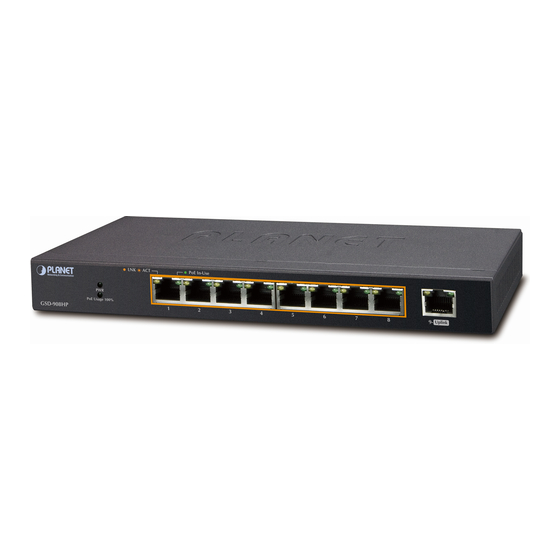
Page 9: Hardware Description
Before connecting any network device to the GSD-908HP, please read this chapter carefully. 2.1 Front Panel The front panel of the GSD-908HP PoE Ethernet Switch consists of 9x Auto-Sensing 10/100/1000Mbps Ethernet RJ-45 Ports. The LED Indicators are also located on the RJ-45 ports of the PoE Ethernet Switch. -
Page 10: Rear Panel
Cat.5 UTP, 2-pair RJ-45 1000Base-T Cat.5/5e/6 UTP, 4-pair RJ-45 Any Ethernet devices like hubs/PCs can connect to the GSD-908HP PoE Ethernet Switch by using straight-through wires. The nine RJ-45 ports are auto-MDI/MDI-X, which can be used on straight-through or crossover cable. -
Page 11: Installation
3. Installation 3.1 Desktop Installation To install the PoE Ethernet Switch on desktop, simply follow the following steps: Step 1: Attach the rubber feet to the recessed areas on the bottom of the PoE Ethernet Switch, as shown in Figure 3-1. Figure 3-1: Place the PoE Ethernet Switch on the Desktop Step 2: Place the PoE Ethernet Switch on desktop near an AC power source. -
Page 12: Magnet Installation
Step 5: Supply power to the PoE Ethernet Switch. A. Connect one end of the power cable to the DC power adapter and connect its DC plug connector to the PoE Ethernet Switch. B. Connect the power plug of the power cable to a standard wall outlet. When the PoE Ethernet Switch receives power, the Power LED should remain solid Green. -
Page 13: Wall Mount Installation
Step 4: Proceed with Step 4 and Step 5 of session 3.1 Desktop Installation to connect the network cabling and supply power to your PoE Ethernet Switch. 1. Select the installation surface carefully. If the magnetic surface is not providing enough magnetism, the reliability of this instal- lation will be influenced. -
Page 14: Protective Grounding Cable Installation
Step 4: Align two wall type holes at the bottom of the PoE Ethernet Switch with screws and hang the PoE Ethernet Switch on it. Figure 3-3: PoE Ethernet Switch Wall Mount Installation 3.4 Protective Grounding Cable Installation The proper connection of the protective grounding cable is not only for quickly releasing the over voltage and over current from lightning strike, it also provides necessary protection for users’... -
Page 15: Installation Environment Without Grounding Bar
The PoE Ethernet Switch grounding cable should be connected to the engineering land in the IT room because the water hoses and lightning rods are not proper for grounding. 3.4.2 Installation Environment without Grounding Bar 3.4.2.1 With mud land nearby and allowed to bury grounding bar Bury an angle iron or steel pipe (≥0.5m) into the mud land. -
Page 16: Hardware Connection
Category 5/5e/6 UTP cabling. Step 3: Use an Ethernet cable to connect one upstream network devices (such as another switch or router) to the uplink port on the switch, as shown in Figure 3-7. GSD-908HP XDSL Router Internet 1000Base-T UTP... - Page 17 PTZ Camera Figure 3-8: Department / Workgroup PoE Switch Connection Since the GSD-908HP per PoE port supports 51V DC PoE power output, please check and assure the Powered Device’s (PD) accept- able DC power range is 51V DC. Otherwise, it will damage the Note Powered Device (PD).
-
Page 18: Troubleshooting
4. Troubleshooting This chapter contains information to help you solve issues. If the PoE Ethernet Switch is not functioning properly, make sure the PoE Ethernet Switch is set up according to instructions in this manual. The Link / Act LED is not lit Solution: Check the cable connection and remove duplex mode of the PoE Ethernet Switch. -
Page 19: Appendix: A Networking Connection
Appendix: A Networking Connection A.1 PoE RJ-45 Port Pin Assignments PIN NO RJ-45 POWER ASSIGNMENT Power + 1 2 3 4 5 6 7 8 Power + Power - Power - A.2 Switch’s Data RJ-45 Pin Assignments - 1000Mbps, 1000Base-T PIN NO MDI-X BI_DA+... -
Page 20: 10/100Mbps, 10/100Base-Tx
A.3 10/100Mbps, 10/100Base-TX When connecting your PoE Ethernet Switch to another Fast Ethernet switch, a bridge or a hub and a straight or crossover cable are necessary. Each port of the Switch supports auto-MDI/MDI-X detection. That means you can directly connect the Switch to any Ethernet devices without making a crossover cable.
Need help?
Do you have a question about the GSD-908HP and is the answer not in the manual?
Questions and answers