Planet GS-4210 Series Quick Installation Manual
8-/16-/24-/48-port 10/100/1000t + 2-14-port 100/1000x sfp managed switch
Hide thumbs
Also See for GS-4210 Series:
- Installation manual ,
- User manual (353 pages) ,
- Quick installation manual (18 pages)

Related Manuals for Planet GS-4210 Series


Summary of Contents for Planet GS-4210 Series
- Page 1 8-/16-/24-/48-Port 10/100/1000T + 2-/4-Port 100/1000X SFP Managed Switch GS-4210 Series Quick Installation Guide...
-
Page 2: Table Of Contents
Table of Contents 1. Package Contents ..................3 2. Requirements ....................5 3. Terminal Setup ....................6 3.1 Logging on to the Console ............... 7 3.2 Configuring IP Address via the Console .............8 3.3 Storing Current Switch Configuration ............10 4. Starting Web Management ................11 4.1 Logging in to the Managed Switch ............11 4.2 Saving Configuration via the Web ............ -
Page 3: Package Contents
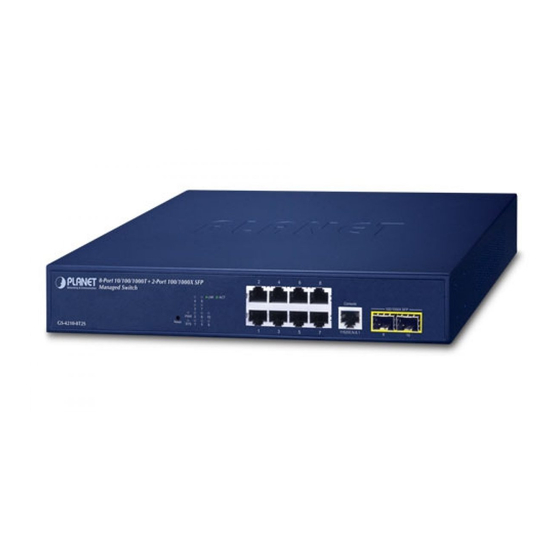
1. Package Contents Thank you for purchasing PLANET GS-4210 Managed Switch series. The descriptions of this series are shown below: PoE Model Description Budget 8-Port 10/100/1000T + 2-Port 100/1000X SFP Managed GS-4210-8T2S Switch 8-Port 10/100/1000T 802.3at PoE + 2-Port 100/1000X GS-4210-8P2S 140W SFP Managed Switch 8-Port 10/100/1000T 802.3at PoE + 2-Port GS-4210-8P2C 10/100/1000T + 2-Port 100/1000X SFP Managed 120W Switch 16-Port Layer 2 Managed Gigabit Ethernet Switch w/2 GS-4210-16T2S SFP Interfaces 16-Port 10/100/1000T 802.3at PoE + 2-Port 100/1000X GS-4210-16P2S 220W SFP Managed Switch 16-Port 10/100/1000T 802.3at PoE + 4-Port Gigabit TP/ GS-4210-16P4C... - Page 4 “Managed Switch” is used as an alternative name in this Quick Installation Guide. Open the box of the Managed Switch and carefully unpack it. The box should contain the following items: z The Managed Switch x 1 z Quick Installation Guide x 1 z RS232 to RJ45 Cable x 1 z Rubber Feet x 4 z Two Rack-mounting Brackets with Attachment Screws x 1 z Power Cord x 1 z SFP Dust-proof Cap Models SFP Dust-proof Caps GS-4210-8P2C GS-4210-8T2S GS-4210-8P2S GS-4210-16T2S GS-4210-16P2S...
-
Page 5: Requirements
2. Requirements z The Managed Switch provides local and remote login interface for management purposes. The following equipment is necessary for further management: z Workstations running Windows 7/8/10/11, macOS 10.12 or later, Linux Kernel 2.6.18 or later, or other modern operating systems are compatible with TCP/IP Protocols. z Workstations are installed with Ethernet NIC (Network Interface Card) z Serial Port Connection (Terminal) The above Workstations come with COM Port (DB9) or USB-to-RS-232 converter. -
Page 6: Terminal Setup
3. Terminal Setup To configure the system, connect a serial cable to a COM port on a PC or notebook computer while the other end to RJ45 console port of the Managed Switch. PC / Workstation with Terminal Emulation Software Managed Switch RS232 to RJ45 Cable Serial Port RJ45 Console Port Figure 3-1: Managed Switch Console Connectivity A terminal program is required to make the software connection to the Managed Switch. -
Page 7: Logging On To The Console
3.1 Logging on to the Console Once the terminal is connected to the device, power on the Managed Switch and the terminal will run self testing procedures. Then, the following message asks to log in user name and password. The factory default user name and password are shown as follows and the login screen in Figure 3-3 appears. 1. The following console screen is based on the firmware version before February of 2024. 2. The following console screen based on the GS-4210-24T4S is the same as those of the GS-4210 series. -
Page 8: Configuring Ip Address Via The Console
(2) This device must accept any interference received, including interference that may cause undesired operation. Made in Taiwan PLANET Technology Corp. Figure 3-4: Managed Switch MAC ID Label Enter the default username and password, then set a new password according to the rule-based prompt and confirm it. Upon success, press any key to return to the... - Page 9 To check the current IP address or modify a new IP address for the Managed Switch, please use the procedures as follows: Display of the current IP address 1. On “GS-4210-24T4S#” prompt, enter “show ip”. 2. The screen displays the current IP address, subnet mask and gateway shown in Figure 3-6.
-
Page 10: Storing Current Switch Configuration
5. Repeat Step 1 to check if the IP address has changed. If the IP is successfully configured, the Managed Switch will apply the new IP address setting immediately. You can access the Web interface of Managed Switch through the new IP address. If you are not familiar with console command or the related parameter, enter “?” anytime in console to get the help description. -
Page 11: Starting Web Management
4. Starting Web Management The following shows how to start up the Web Management of the Managed Switch. Note the Managed Switch is configured through an Ethernet connection. Please make sure the manager PC must be set to the same IP subnet address. For example, the default IP address of the Managed Switch is 192.168.0.100;... - Page 12 (1) This device may not cause harmful interference and (2) This device must accept any interference received, including interference that may cause undesired operation. PLANET Technology Corp. Made in Taiwan Figure 4-3: Industrial Managed Switch MAC ID Label...
- Page 13 Figure 4-4: Login Screen 6. After logging in, you will be prompted to change the initial password to a perma- nent one. Figure 4-5: Create a New Password 7. Enter the default username and password, then set a new password according to the rule-based prompt and confirm it. Upon success, press any key to return to the login prompt. Log in with “admin” and the “new password” to access the Web interface. Figure 4-6: Web Main Screen of Managed Switch...
- Page 14 The Switch Menu on the left of the Web page lets you access all the commands and statistics the Managed Switch provides. Figure 4-7: Switch Menu Now, you can use the Web management interface to continue the switch management. Please refer to the user’s manual for more.
-
Page 15: Saving Configuration Via The Web
4.2 Saving Configuration via the Web Save all applied changes and set the current configuration as a startup configuration. The startup-configuration file will be loaded automatically across a system reboot. 1. Click ”SAVE > Save Configurations to FLASH” to log in “Configuration Manager” Page. 2. Press the “Apply” button to save running configuration as startup configuration. -
Page 16: Recovering Back To Default Configuration
5. Recovering Back to Default Configuration IP address has been changed or admin password has been forgotten – To reset the IP address to the default IP Address “192.168.0.100” and the user name password to factory default mode (default password is admin or sw + the last 6 characters of the MAC ID in lowercase), press the hardware-based reset button on the side panel for about 10 seconds. After the device is rebooted, you can log in the management Web interface within the same subnet of 192.168.0.xx. 8-Port 10/100/1000T 802.3at PoE + 2-Port 100/1000X SFP Managed Swi Console Reset GS-4210-8P2C... - Page 17 16-Port 10/100/1000T + 2-Port 100/1000X SFP Managed Switch 1000 Reset 1000 GS-4210-16T2S 10/100 Reset Figure 5-4: GS-4210-16T2S Reset Button + 2-Port 100/1000X SFP Managed Switch 16-Port 10/100/1000T 802.3at PoE GS-4210-16P2S 1000 1000 10/100 RESET PoE-in-Use Reset Figure 5-5: GS-4210-16P2S Reset Button Console Reset 1000...
- Page 18 + 2-Port 100/1000X SFP Managed Switch 24-Port 10/100/1000T 802.3at PoE GS-4210-24P2S 1000 1000 10/100 RESET PoE-in-Use Reset Figure 5-8: GS-4210-24P2S Reset Button 1000 LNK/ACT 1000 LNK/ACT PoE-in-Use 10/100 LNK/ACT LNK/ACT Reset GS-4210-24P4C Reset Figure 5-9: GS-4210-24P4C/GS-4210-24PL4C Reset Button 1000 1000 10/100 Reset Reset...
- Page 19 Console PoE-in-Use LNK/ACT GS-4210-48P4S Reset 115200, N, 8, 1 Reset Figure 5-12: GS-4210-48P4S Reset Button...
-
Page 20: Customer Support
6. Customer Support Thank you for purchasing PLANET products. You can browse our online FAQ resource and User’s Manual on PLANET Web site first to check if it could solve your issue. If you need more support information, please contact PLANET switch support team. ANET online FAQs: http://www.planet.com.tw/en/support/faq Switch support team mail address: support@planet.com.tw GS-4210 Series User’s Manual: https://www.planet.com.tw/en/support/downloads?&method=keyword&keyword=GS- 4210&view=3#list Copyright © PLANET Technology Corp. 2024. Contents are subject to revision without prior notice. PLANET is a registered trademark of PLANET Technology Corp. All other trademarks belong to their respective owners.
Need help?
Do you have a question about the GS-4210 Series and is the answer not in the manual?
Questions and answers