Table of Contents
Advertisement
Quick Links
Download this manual
See also:
Service Manual
Advertisement
Table of Contents
Troubleshooting

Subscribe to Our Youtube Channel
Related Manuals for Waters 2410


Summary of Contents for Waters 2410
- Page 1 Waters 2410 Differential Refractometer Operator’s Guide 34 Maple Street Milford, MA 01757 71500241002, Revision 3...
- Page 2 This guide is believed to be complete and accurate at the time of publication. In no event shall Waters Corporation be liable for incidental or consequential damages in connection with or arising from the use of this guide.
- Page 3 Note: When you use the instrument, follow generally accepted procedures for quality control and methods development. If you observe a change in the retention of a particular compound, in the resolution between two compounds, or in peak shape, immediately take steps to determine the reason for the changes.
- Page 4 Caution: Use caution when working with any polymer tubing under pressure: • Always wear eye protection when near pressurized polymer tubing. • Extinguish all nearby flames. • Do not use Tefzel tubing that has been severely stressed or kinked. • Do not use Tefzel tubing with tetrahydrofuran (THF) or concentrated nitric or sulfuric acids.
- Page 5 Precauzione: prestare attenzione durante le operazioni con i tubi di polimero sotto pressione: • Indossare sempre occhiali da lavoro protettivi nei pressi di tubi di polimero pressurizzati. • Estinguere ogni fonte di ignizione circostante. • Non utilizzare tubi Tefzel soggetti a sollecitazioni eccessive o incurvati. •...
- Page 6 Caution: The user shall be made aware that if the equipment is used in a manner not specified by the manufacturer, the protection provided by the equipment may be impaired. Attention: L’utilisateur doit être informé que si le matériel est utilisé d’une façon non spécifiée par le fabricant, la protection assurée par le matériel risque d’être défectueuses.
- Page 7 Caution: To avoid possible electrical shock, power off the instrument and disconnect the power cord before servicing the instrument. Attention: Afin d’éviter toute possibilité de commotion électrique, mettez hors tension l’instrument et débranchez le cordon d’alimentation de la prise avant d’effectuer la maintenance de l’instrument.
- Page 8 Commonly Used Symbols Direct current Courant continu Gleichstrom Corrente continua Corriente continua Alternating current Courant alternatif Wechs el s t r om Corrente alternata Corriente alterna Protective conductor terminal Borne du conducteur de protection Schutzleiteranschluss Terminale di conduttore con protezione Borne del conductor de tierra Frame or chassis terminal Borne du cadre ou du châssis...
- Page 9 Commonly Used Symbols (Continued) Caution, hot surface or high temperature Attention, surface chaude ou température élevée Vorsicht, heiße Oberfläche oder hohe Temperatur Precauzione, superficie calda o elevata temperatura Precaución, superficie caliente o temperatura elevada Caution, risk of electric shock (high voltage)•Attention, risque de commotion électrique (haute tension) Vorsicht, Elektroschockgefahr (Hochspannung) Precauzione, rischio di scossa elettrica (alta tensione)
- Page 10 Intended Use ® The Waters 2410 Differential Refractometer can be used for in-vitro diagnostic testing to analyze many compounds, including diagnostic indicators and therapeutically monitoredcompounds. When you develop methods, follow the “Protocol for the Adoption ofAnalytical Methods in the Clinical Chemistry Laboratory,”...
-
Page 11: Table Of Contents
Table of Contents How to Use This Guide Chapter 1 Waters 2410 Theory of Operation Overview ......................1-1 Theory of Operation ..................1-2 1.2.1 Optical Refraction ................1-2 1.2.2 Differential Refractometry ..............1-7 1.2.3 Common RI Detection Problems ............1-9 Principles of Operation.................. - Page 12 Component Connection Overview ..............3-1 Making IEEE-488 Signal Connections ............3-3 3.2.1 Connecting to a Waters Data System Using the IEEE-488 Bus ..3-3 3.2.2 Connecting to a Waters PowerLine System Controller ..... 3-7 3.2.3 Connecting to a Manual Injector ............3-7 Making Non-IEEE-488 Signal Connections ...........
- Page 13 5.2.2 Scale Factor Guidelines ..............5-10 5.2.3 Time Constant Guidelines ...............5-11 5.2.4 Temperature Guidelines (Ext1 °C, Ext2 °C, Int °C) .......5-12 5.2.5 Polarity Guidelines ................5-13 Starting Up the 2410 Refractometer ..............5-13 Shutting Down the 2410 Refractometer ............5-15 Chapter 6 Maintenance Procedures Cleaning the Fluidic Path.................6-1...
- Page 14 Appendix C Warranty Information Limited Express Warranty ................C-1 Shipments, Damages, Claims, and Returns.............C-4 Index Table of Contents...
- Page 15 2410 Refractometer ..............3-11 Chart Mark Connections Between the 2690 Separations Module and the 2410 Refractometer ..............3-12 3-10 Chart Mark and Auto Zero Connections Between the 2690 Separations Module and the 2410 Refractometer ....3-13 Table of Contents...
- Page 16 Auto Zero Connectionto a Manual Injector ........... 3-17 3-15 Chart Mark Connections to a Manual Injector ........3-18 3-16 2410 Refractometer External Column Heater Ports ......3-20 Display, LED Indicators, and Keypad............5-2 Effects of Sensitivity Settings ..............5-10 Effects of Filter Time Constant Settings ..........5-12 Removing and Replacing Fuses...............
- Page 17 Installation Site Requirements ..............2-3 Component Connection Summary............3-1 Waters 2410 Refractometer Inject Start Connections......3-6 Waters 2410 Connections to a Manual Injector ........ 3-7 Waters 2410 Analog-Out/Event-In Connections ....... 3-9 Auto Zero Connections Between the 2690 Separations Module and the 2410 Refractometer ............3-10 Chart Mark Connections Between the 2690 Separations Module and the 2410 Refractometer ............
- Page 18 Resolution Troubleshooting ............7-10 Incorrect Results Troubleshooting..........7-12 User Diagnostics ................7-14 Waters 2410 Hardware Troubleshooting......... 7-16 Operational Specifications ..............A-1 Integrator Output................A-2 Optical Component Specifications............A-2 Environmental Specifications ............A-2 Dimensions ..................A-3 Electrical Specifications ..............A-3 Power Source Specification ..............A-3 Recommended Spare Parts ...............B-1 Waters 2410 Warranty Periods..............C-4...
-
Page 19: Purpose Of This Guide
How to Use This Guide Purpose of This Guide The Waters 2410 Differential Refractometer Operator’s Guide describes the features and use of the ® Waters 2410 Differential Refractometer and provides installation and maintenance procedures. Audience This guide is intended for use by anyone interested in installing, using, maintaining, and troubleshooting the 2410 differential refractometer. - Page 20 Includes warranty and service information for the 2410 differential Information refractometer. Related Documents The following table lists other documents related to the operation of the Waters 2410 Differential Refractometer. Waters 2690 Separations Module Describes the procedures for unpacking, installing, using, Operator’s Guide...
- Page 21 Conventions Used in This Guide This guide uses the following conventions to make text easier to understand. • Bold text indicates user action. For example: Press 0, then press Enter for the remaining fields. • Italic text denotes new or important words, and is also used for emphasis. For example: An instrument method tells the software how to acquire data.
- Page 22 xxii...
-
Page 23: Waters 2410 Theory Of Operation
Chapter 1 Waters 2410 Theory of Operation Overview ............1-1 Theory of Operation .......... 1-2 Principles of Operation........1-10... -
Page 25: Overview
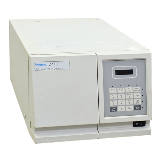
The Waters 2410 Differential Refractometer, shown in Figure 1-1, is a differential refractive index detector designed for high performance liquid chromatography applications. It can operate as a stand-alone unit with an integrator or chart recorder, or with a Waters system controller or Waters data system. -
Page 26: Theory Of Operation
Range and Sensitivity The 2410 detector functions with solvents with refractive indices between 1.00 and 1.75. The measurement range of the instrument is 5 × 10 to 5 × 10 –8 –3 refractive index units full scale (RIUFS). Features Features of the 2410 differential refractometer include: •... - Page 27 The refractive index of a medium has a specific value that changes with the wavelength of the incident light beam. Since the 2410 differential refractometer uses monochromatic light at a fixed wavelength, the effect of different wavelengths of light on RI is not discussed in this guide.
-
Page 28: Effect Of Density On Ri
Weight Percent Sucrose in Water Density (g/mL) Weight Percent Methanol in Water Density (g/mL) Figure 1-2 Effect of Density on RI Waters 2410 Theory of Operation... -
Page 29: Refraction Of Light
Measuring Refraction The extent to which a beam of light is refracted when it enters a medium depends on two factors: • The angle at which the light enters the new medium (the angle of incidence) • The refractive indices of the new media The angle of a refracted light beam through the new medium is its angle of refraction. -
Page 30: Presence Of Sample Changes The Photodiode Signal
Flow Cell of Flow Cell Reference Side of Flow Cell Reference Reference Side Reference Side of Flow Cell of Flow Cell Side of Flow Cell Incident Light Figure 1-4 Presence of Sample Changes the Photodiode Signal Waters 2410 Theory of Operation... -
Page 31: Differential Refractometry
1.2.2 Differential Refractometry The 2410 differential refractometer can measure extremely small changes in refractive index to detect the presence of sample. The small difference in RI between a reference solution and a sample solution is referred to as ∆n. ∆n is expressed in refractive index units (RIU). - Page 32 As a result, the reference external angle of deflection ( φ ) does not change until a change in the RI of the sample causes the light beam to be refracted from its zero position. Waters 2410 Theory of Operation...
-
Page 33: Common Ri Detection Problems
θ = Angle of incidence (in radians) Effect of Refraction on the Photodiode Signal The change in φ determines the shift (∆x) of the light beam on the photodiode. Because the 2410 differential refractometer uses a dual-pass optics bench assembly, the light beam passes through the flow cell twice before reaching the photodiode, doubling the image shift. -
Page 34: Principles Of Operation
• Fluidics • Optics • Electronics 1.3.1 Fluidics The fluidic path of the 2410 refractometer includes the following components, some of which are shown in Figure 1-6: • Countercurrent heat exchanger • Flow cell, with sample and reference sides • Solenoid valve •... -
Page 35: Waters 2410 Refractometer Fluidics
The other prism is the reference side of the flow cell. It is filled with clean solvent when you purge the 2410 refractometer during equilibration. When you switch from purge to normal operation, the solenoid valve opens and the pressure relief valve shuts, stopping the flow of solvent through the reference prism but leaving the cell filled with solvent. - Page 36 Figure 1-7 indicates the paths of solvent and sample in the 2410 refractometer during normal operation and during a purge. Table 1-1 provides the inner diameters of the sample and reference fluidic lines.
-
Page 37: Waters 2410 Refractometer Fluidic Paths
5. Passes through the solenoid valve to the outlet tubing port. Fluidic Path During Purge When you purge the 2410 refractometer fluidic path, solvent: 1. Flows in through inlet tubing port. 2. Passes through the Sample In tube of the countercurrent heat exchanger. -
Page 38: Optics
7. Flows out through the Reference Out tube of the countercurrent heat exchanger. 8. Flows out through the pressure relief valve to the purge outlet tubing port. 1.3.2 Optics The 2410 refractometer optics bench assembly (Figure 1-8) consists of the following components: • LED source lamp • LED lens mask •... -
Page 39: Electronics
Figure 1-8 Waters 2410 Differential Refractometer Optics Bench Assembly Light Path 1.3.3 Electronics The 2410 refractometer has both analog and digital components, and includes hardware such as the front panel keyboard and printed circuit (PC) boards and their interconnections. The following PC boards are included in the 2410 refractometer electronics. - Page 40 1-16 Waters 2410 Theory of Operation...
-
Page 41: Installing The 2410 Refractometer
Chapter 2 Installing the 2410 Refractometer Introduction ............2-1 Site Selection and Power Requirements.... 2-2 Unpacking and Inspection ......... 2-4 Making Electrical Power Connections ....2-5 Making Fluidic Connections ......2-5... -
Page 43: Introduction
Installing the 2410 Refractometer This chapter describes the procedures for selecting the site for installing the Waters 2410 Differential Refractometer, unpacking and inspecting the instrument, installing fuses, and making fluidic connections. For information on connecting the 2410 refractometer to other devices, see Chapter 3. -
Page 44: Site Selection And Power Requirements
fluidic connections are located (see Section 2.5, Making Fluidic Connections). 2.2 Site Selection and Power Requirements Reliable operation of your 2410 refractometer depends on a proper installation site and a suitable power supply. Site Selection Requirements Install the Waters 2410 Differential Refractometer in an area that meets the requirements listed in Table 2-1. -
Page 45: Installation Site Requirements
Level (ensures proper drip tray function) Power Requirements The 2410 refractometer, which operates over the range 100 Vac to 240 Vac, is shipped from the factory with two 2.0 A fuses. Caution: To avoid electrical shock, power off the 2410 refractometer and unplug the power cord from the rear panel receptacle before you replace a fuse. -
Page 46: Unpacking And Inspection
Receptacle Fuse Holder TP01531 Figure 2-3 Waters 2410 Refractometer Rear Panel To replace a fuse in the 2410 refractometer, see Section 6.2, Replacing Fuses. 2.3 Unpacking and Inspection The Waters 2410 refractometer shipping carton contains: • Certificate of Structural Validation •... -
Page 47: Making Electrical Power Connections
This section describes the procedures for connecting the 2410 refractometer to: • A column or another detector • A waste container • The drip tray The fluidic connections for the 2410 refractometer are located to the left of the keypad on the front panel (Figure 2-4). Making Electrical Power Connections... -
Page 48: Connecting A Column Or Second Detector
TP01532 Figure 2-4 Fluidic Connections 2.5.1 Connecting a Column or Second Detector Note: If you are using more than one detector in your system, the Waters 2410 Differential Refractometer must be connected as the last detector in line. Required Materials •... -
Page 49: Connecting To Waste
2.5.2 Connecting to Waste Because the 2410 refractometer flow cell is very sensitive to backpressure, be sure to use waste tubing that is 0.040-inch ID and that is no more than 18 to 24 inches (45 to 60 cm) long. -
Page 50: Connecting To A Drip Tray
flow cell could be damaged if this pressure is exceeded. 2.5.3 Connecting to a Drip Tray The 2410 refractometer contains a drip tray underneath the flow cell behind the front panel to direct solvent leaks to the front of the unit. - Page 51 Chapter 3 Making Signal Connections Component Connection Overview ....3-1 Making IEEE-488 Signal Connections ..... 3-3 Making Non-IEEE-488 Signal Connections ..3-8 Connecting the External Column Heaters ..3-19...
-
Page 53: Making Signal Connections
This chapter describes procedures for making signal connections between the Waters 2410 Differential Refractometer and other HPLC system components. 3.1 Component Connection Overview Table 3-1 summarizes the signal connections needed to connect the 2410 refractometer to other HPLC system components. Table 3-1 Component Connection Summary... -
Page 54: Waters 2410 Differential Refractometer Rear Panel
The signal connections you need to make to your 2410 refractometer depend on the signal connections available on the other instruments in your HPLC system. Figure 3-2 provides an overview of the steps to follow to connect the 2410 refractometer to other instruments in your HPLC system. -
Page 55: Making Ieee-488 Signal Connections
3.2.1 Connecting to a Waters Data System Using the IEEE-488 Bus You can use the IEEE-488 bus to connect the 2410 refractometer to a Waters data system in any one of the following configurations (see Figure 3-3, Figure 3-4, and Figure 3-5): •... -
Page 56: Waters Millennium System Ieee-488 Connections
• Waters 845 or 860 system through a LAC/E module (Figure 3-4) • Waters 2690 Separations Module as part of an Alliance system (Figure 3-5). Bus LAC/E or Network LAC/E Card Millennium Chromatography Manager IEEE-488 Cables IEEE-488 Connector 600 Series... -
Page 57: Waters Alliance System Ieee-488 Connections
Figure 3-5 Waters Alliance System IEEE-488 Connections Setting the IEEE-488 Address Like all other IEEE-488 devices, the 2410 refractometer requires a unique IEEE-488 address to be recognized by an IEEE-488 controller, such as a Millennium Chromatography Manager, busLAC/E module, or an Alliance or PowerLine System Controller. -
Page 58: Waters 2410 Refractometer Inject Start Connections
Note: Depending on your system configuration, the inject start signal can be transmitted through the IEEE-488 interface or the analog-out/event-in connectors on the 2410 refractometer rear panel. For information on non-IEEE-488 connections, see Section 3.3, Making Non-IEEE-488 Signal Connections. Table 3-2 summarizes the inject start connections for different system configurations. -
Page 59: Connecting To A Waters Powerline System Controller
If you are using a manual injector with your IEEE-488 system, connect the signal cables from the rear panel connector on the 2410 refractometer to the injector as indicated in Table 3-3. Table 3-3 Waters 2410 Connections to a Manual Injector... -
Page 60: Making Non-Ieee-488 Signal Connections
3.3 Making Non-IEEE-488 Signal Connections To connect the 2410 refractometer to instruments that lack an IEEE-488 bus, you use the analog-out/event-in (I/O) connectors on the rear panel (Figure 3-7). Figure 3-7 shows the two I/O connectors (and their corresponding pin-outs) on the 2410 refractometer rear panel. Table 3-4 describes the functions of each connector. -
Page 61: Waters 2410 Rear Panel Analog-Out/Event-In Connectors
11 Compressed Out – 12 Chassis Ground 12 Chassis Ground Figure 3-7 Waters 2410 Rear Panel Analog-Out/Event-In Connectors Table 3-4 describes the functions of the 2410 refractometer analog-out/event-in connectors. Table 3-4 Waters 2410 Analog-Out/Event-In Connections Signal Connections Description Chart Mark... -
Page 62: Connecting To A Stand-Alone 2690 Separations Module
• Both chart mark and auto zero on inject Generating Auto Zero on Inject To generate the auto zero function on the 2410 refractometer at the start of an injection from the 2690 Separations Module, make the connections shown in Table 3-5 and Figure 3-8. -
Page 63: Auto Zero Connections Between The 2690 Separations Module And The 2410 Refractometer
2410 Refractometer Generating Chart Mark on Inject To generate the chart mark function on the 2410 refractometer at the start of an injection from the 2690 Separations Module, make the connections shown in Table 3-6 and Figure 3-9. -
Page 64: Chart Mark Connections Between The 2690 Separations Module And The 2410 Refractometer
To generate both a chart mark and an auto zero signal from the 2690 Separations Module to the 2410 refractometer, make the connections shown in Table 3-7 and Figure 3-10. Table 3-7 Chart Mark and Auto Zero Connections Between the 2690 Separations Module... -
Page 65: Connecting To The Waters 745/745B/746 Data Module
2690 Separations Module and the 2410 Refractometer 3.3.2 Connecting to the Waters 745/745B/746 Data Module To send an integrator analog output signal (–2V to +2V) from the 2410 refractometer to the Waters 745/745B/746 Data Module, make the connections shown in Table 3-8 and Figure 3-11. -
Page 66: Connections To A Waters 745/745B/746 Data Module
Note: If you use another manufacturer’s integrator or A/D device, you may need to connect the Chassis Ground (pin 12) to the 2410 detector’s Integrator Out– (black lead) or an equivalent connection. Waters 2410 Refractometer... -
Page 67: Connecting To A Chart Recorder
3.3.3 Connecting to a Chart Recorder To send an analog output signal from the 2410 refractometer to a chart recorder, make the connections shown in Table 3-9 and Figure 3-12. Table 3-9 Analog Output Connections to a Chart Recorder Chart Recorder... -
Page 68: Connecting To The Waters 845/860 Expertease System
3.3.4 Connecting to the Waters 845/860 ExpertEase System To send an integrator analog output signal (–2V to +2V) from the 2410 refractometer to an 845/860 ExpertEase System (through a two-channel SAT/IN module), make the connections shown in Table 3-10 and Figure 3-13. -
Page 69: Auto Zero Connections To A Manual Injector
To send an auto zero or chart mark signal from a manual injector to the 2410 refractometer, make the connections shown in Table 3-11 and Figure 3-14 and Table 3-12 and Figure 3-15. -
Page 70: Polarity Connections
• Polarity 2 serves as an external input (Polarity 1) enable • When Polarity 2 is open (not connected), the +/– key on the 2410 front panel or an IEEE-488 connected data system (such as the Millennium Chromatography Manager or PowerLine) determines the polarity (see Section 5.2.5, Polarity Guidelines). -
Page 71: Connecting The External Column Heaters
3.4 Connecting the External Column Heaters The Waters 2410 Differential Refractometer can control up to two optional external column heaters through the EXT 1 and EXT 2 ports l on the rear panel of the detector (Figure 3-16). The ports are standard 9-pin DIN connectors. -
Page 72: Refractometer External Column Heater Ports
Waters 2410 Refractometer Rear Panel External Column Heater Ports EXT 2 EXT 1 Figure 3-16 2410 Refractometer External Column Heater Ports 3-20 Making Signal Connections... - Page 73 Chapter 4 Preparing Solvents Common Solvent Problems ....... 4-1 Selecting a Solvent ..........4-2 Solvent Degassing ..........4-4...
-
Page 75: Preparing Solvents
4.1 Common Solvent Problems The 2410 refractometer measures changes in the concentration of the solution flowing through the sample side of the flow cell (see Section 1.2, Theory of Operation). However, factors other than the presence of dissolved sample molecules can affect a solution’s refractive index. Common problems include: •... -
Page 76: Selecting A Solvent
4.2 Selecting a Solvent An ideal solvent for your analysis: • Has good solubility characteristics for your application • Has a significantly different refractive index (RI) than the sample components • Gives satisfactory baseline noise performance • Provides optimum optical sensitivity characteristics Solvent Quality Use spectral-grade or HPLC-grade solvents to ensure: •... -
Page 77: Refractive Indices Of Common Solvents
Tetrahydrofuran (THF) When you use unstabilized THF, ensure that your solvent is fresh. Previously opened bottles of THF contain peroxide contaminants, which cause baseline drift. Caution: THF contaminants (peroxides) are potentially explosive if concentrated or taken to dryness. Refractive Indices of Common Solvents Table 4-1 lists the refractive indices for some common chromatographic solvents. - Page 78 Table 4-1 Refractive Indices of Common Solvents (Continued) Solvent Solvent Acetic acid 1.372 Chloroform 1.443 Isopropyl chloride 1.378 Ethylene dichloride 1.445 Isopropanol 1.38 Carbon tetrachloride 1.466 n-Propanol 1.38 Dimethyl sulfoxide (DMSO) 1.477 Methylethylketone 1.381 Toluene 1.496 Diethyl amine 1.387 Xylene ~1.50 n-Propyl chloride 1.389...
-
Page 79: Solvent Degassing
4.3.1 Gas Solubility The amount of gas that can dissolve in a given volume of liquid depends on: • The chemical affinity of the gas for the liquid • The temperature of the liquid • The pressure applied to the liquid Changes in the composition, temperature, or pressure of the mobile phase can lead to outgassing. -
Page 80: Solvent Degassing Considerations
Sparging Sparging removes gases from solution by displacing dissolved gases in the solvent with a less soluble gas, usually helium. Well-sparged solvent improves pump performance. Helium sparging brings the solvent to a state of equilibrium, which may be maintained by slow sparging or by keeping a blanket of helium over the solvent. - Page 81 The in-line degasser is available as an option or factory-installed in the Waters 2690 Separations Module, XE model. When you are using the 2690 Separations Module with the 2410 refractometer, set the in-line degasser to “continuous” degas mode. Select the most efficient degassing operation for your application. To remove dissolved gas quickly, consider the following degassing considerations.
- Page 82 Preparing Solvents...
- Page 83 Chapter 5 Using the 2410 Refractometer Using the Front Panel ........5-1 Selecting Parameter Values........ 5-9 Starting Up the 2410 Refractometer....5-13 Shutting Down the 2410 Refractometer ..5-15...
-
Page 85: Using The 2410 Refractometer
Remote Control Mode You can use the 2410 refractometer as part of a system configured and controlled by a Waters data system, such as the Millennium Chromatography Manager, or a Waters PowerLine system controller (including the 2690 Separations Module). If you set up the 2410 refractometer in this way, follow the instructions in the appropriate data system or controller operator’s guide to set... -
Page 86: Display, Led Indicators, And Keypad
Ext 2 ° C Int ° C Ext 1 ° C Remote % Full Scale Set ° C Filter Auto Zero Sens +/− Mark Purge Scale Factor Clear Enter Function Figure 5-1 Display, LED Indicators, and Keypad Using the 2410 Refractometer... -
Page 87: Indicator Led Functions
Illuminates when the temperature of the internal oven is displayed in the four-character LED; also illuminates when you are changing the temperature. Remote Illuminates when the 2410 refractometer is under the control of a remote controller. % Full Scale Illuminates when the chart recorder output of the 2410 differential refractometer (as a percent referenced to 10 mV) is displayed in the four-character LED. -
Page 88: Keypad Functions
Most keys also have a secondary function, shown in smaller type (on the key) above the primary function or number. To use a secondary function, press the 2nd Func key, then the key labeled with the secondary function. For example, press 2nd Func, then Purge to set the 2410 refractometer to purge mode. - Page 89 Scale factor does not affect integrator or IEEE-488 data output; it functions as an attenuator for the chart recorder output. See Section 5.2.2, Scale Factor Guidelines, for more information. Enter – Saves parameter settings in the memory of the 2410 refractometer. Enter Clear – Erases unsaved parameter entries.
- Page 90 1. Press 2nd Func followed by Ext1 °C, Ext2 °C, or Int °C (for either column heater or for the internal oven). The temperature of the column heater or oven appears in the display, and the corresponding indicator lights up. 2. Press 2nd Func, Set °C, Clear, then press Enter. Using the 2410 Refractometer...
- Page 91 Table 5-2 Keypad Functions (Continued) Description Filter – Adjusts the time constant of the noise filter to achieve the optimum Filter signal-to-noise ratio. Repeated pressing of the Filter key scrolls through the values 0.2, 1, 3, and 10. Press Enter when you reach the value you want. The default value is 1.
- Page 92 3. Press Enter to save the new value. If you enter an unacceptable value, the 2410 refractometer beeps and returns to the previous value. Changing the Filter Value To change the value for the filter: 1. Press the 2nd Func key.
-
Page 93: Selecting Parameter Values
You can adjust the noise level, peak height, peak direction, and the temperatures of the internal oven and column heaters to optimize the performance of the 2410 refractometer. This section provides guidelines and considerations for selecting parameter values that are best suited to your application. -
Page 94: Scale Factor Guidelines
----------------- - % FS where: %FS = the % Full Scale value displayed in the four-character LED display when the 2410 refractometer detects the largest peak (the % Full Scale display reads 100 for a 10 mV signal at the chart recorder output). -
Page 95: Time Constant Guidelines
Chart Recorder Output Considerations Use of the 2410 refractometer with both a an integrator and a chart recorder is possible because you can program the 2410 refractometer with an offset from 0 to 50 mV. The maximum voltage on the recorder output is always 2 V regardless of the sensitivity or scale factor setting;... -
Page 96: Temperature Guidelines (Ext1 °C, Ext2 °C, Int °C)
5.2.4 Temperature Guidelines (Ext1 °C, Ext2 °C, Int °C) The 2410 refractometer permits temperature ranges of 30 to 50 °C for the internal oven (Int °C key), and from 0 to 150 °C for the two external column heaters (Ext1 °C, Ext2 °C). The general operating temperature for the internal oven should be set about 5 °C above the ambient temperature... -
Page 97: Polarity Guidelines
5.3 Starting Up the 2410 Refractometer To start up the 2410 refractometer: 1. Press the On/Off switch located on the lower front right corner of the unit. While the 2410 refractometer performs internal tests, the four-character LED display flashes all 8’s, goes blank for eight seconds, then displays a flashing “–”... - Page 98 7. Allow the 2410 refractometer to warm up for 24 hours before operating it. Remote Mode The 2410 refractometer operates in remote mode when it is under active control by a system controller through the IEEE-488 interface. You can configure remote control of the 2410 refractometer with Waters systems such as the: •...
-
Page 99: Shutting Down The 2410 Refractometer
Note: Do not power off the 2410 refractometer unless you are storing it. If you are not storing the 2410 refractometer, set the flow rate to 0.1 mL/min and keep the pump or solvent delivery system operating. This minimizes the amount of time the 2410 refractometer needs for reequilibration when you use it again. - Page 100 5-16 Using the 2410 Refractometer...
- Page 101 Chapter 6 Maintenance Procedures Cleaning the Fluidic Path ........6-1 Replacing Fuses..........6-3...
-
Page 103: Maintenance Procedures
Maintenance Procedures The maintenance of the 2410 refractometer described in this chapter involves cleaning the fluidic path and replacing fuses. When you perform maintenance procedures on your 2410 differential refractometer, keep the following safety considerations in mind: Caution: To prevent the possibility of electrical shock, never disconnect an electrical assembly while power is applied to the Waters 2410 Differential Refractometer. -
Page 104: Before You Begin
(a pH value of 6.0 to 7.0). Note: If you use 6 N nitric acid, do so with care. If you operate the 2410 refractometer at high sensitivities, you may need to flush the system extensively with water to remove all traces of the nitric acid. -
Page 105: Replacing Fuses
9. Switch the pump or solvent delivery system back to the mobile phase. Flush for 5 minutes. 10. Take the 2410 differential refractometer out of Purge mode and stop the pump or solvent delivery system. 11. Reattach the column and reequilibrate the 2410 refractometer. -
Page 106: Voltage And Fuse Requirements
Fuse Receptacle Power Input Fuse Holder Figure 6-1 Removing and Replacing Fuses Table 6-1 identifies the 2410 refractometer fuse requirements. Table 6-1 Voltage and Fuse Requirements Nominal Voltage Frequency Required Fuse 100 Vac to 240 Vac 50/60 Hz F 2.0 A... - Page 107 Chapter 7 Troubleshooting Troubleshooting Overview ........ 7-1 Chromatography Troubleshooting..... 7-2 Diagnostics ............7-13 Hardware Troubleshooting ......7-16...
-
Page 109: Troubleshooting
If you determine that a problem is a general chromatography problem, refer to Section 7.2, Chromatography Troubleshooting. If you determine that a problem is with the 2410 refractometer, refer to Section 7.3, Diagnostics. 7.1 Troubleshooting Overview When you troubleshoot your 2410 differential refractometer, keep in mind the following safety... -
Page 110: Chromatography Troubleshooting
Refractometer, for information on start-up diagnostics. Power Surges Power surges, line spikes, and transient energy sources can adversely affect operation. Be sure that the electrical supply used for the 2410 differential refractometer is properly grounded and free from any of these conditions. 7.2 Chromatography Troubleshooting This section contains chromatography troubleshooting tables that describe symptoms, possible causes, and suggested corrective actions. -
Page 111: Abnormal Baseline
Drift, noise, and cycling are common symptoms of an abnormal baseline. Drift The most common difficulty with the 2410 differential refractometer is baseline drift. Drift may be flow-related or result from changing ambient conditions, especially temperature. Determine if drift is flow related by shutting down the solvent delivery system or pump. -
Page 112: Abnormal Baseline Troubleshooting
Keep the system away from air conditioning vents, chance breezes, and direct sunlight. Dirty flow cell Clean flow cell (Section 6.1, Cleaning the Fluidic Path). Baseline drift, descending Leaky flow cell Call Waters Technical Service. Troubleshooting... - Page 113 Table 7-1 Abnormal Baseline Troubleshooting (Continued) Symptom Possible Cause Corrective Action Short-term noise cycling Pump pulsing Add pulse dampener. (30 sec to 60 sec) Inadequate solvent Connect high-flow pulse blending in pump dampener. Use gradient mixer. Flow fluctuating Stabilize flow (see pump operator’s manual).
- Page 114 Clean fluidic path (see Section 6.1, Cleaning the Fluidic Path). Analog output cable not Properly connect cable. properly connected between 2410 and data system or recorder System improperly Plug into different outlet on grounded different electrical circuit. Use power conditioner.
-
Page 115: Erratic Or Incorrect Retention Times
7.2.2 Erratic or Incorrect Retention Times When you troubleshoot retention time problems, check if retention times: • Change from run to run or are constant from run to run, but are outside the allowable range for the assay • Are due to pressure fluctuations that are short-term (with each pump cycle) or long-term (over the course of several minutes) •... - Page 116 Table 7-2 Retention Time Troubleshooting (Continued) Symptom Possible Cause Corrective Action Increased retention Incorrect flow rate Verify flow rate. times Incorrect solvent composition Change solvent composition. Column heater module not on Power on column heater module. Column not equilibrated Equilibrate column. Incorrect column or guard Use correct column or guard column...
-
Page 117: Poor Peak Resolution
7.2.3 Poor Peak Resolution Before you address problems with peak resolution, be certain that peaks elute at the correct retention time. The most common causes of poor peak resolution can also appear as retention time problems. If peak retention times are correct, determine if poor resolution occurs: •... -
Page 118: Resolution Troubleshooting
LED not on. Call Waters Technical Service. Detector not zeroed Auto zero detector baseline. Improper connection Check cabling between unit between 2410 unit and and recorder. recorder Solvent and sample have Select another solvent. similar refractive indices Sensitivity too low Select higher sensitivity. -
Page 119: Incorrect Qualitative/Quantitative Results
Table 7-3 Resolution Troubleshooting (Continued) Symptom Possible Cause Corrective Action Flat-topped peaks Detector not zeroed Auto zero detector baseline. Incorrect recorder input Adjust recorder input voltage voltage, or adjust detector output cable to correct position. Sensitivity too high Select a lower sensitivity. Scale factor too high Select a lower scale factor. -
Page 120: Incorrect Results Troubleshooting
Table 7-4 Incorrect Results Troubleshooting Symptom Possible Cause Corrective Action Decreased peak height Leak in injector Troubleshoot injector. Degraded, contaminated, or Use fresh sample. improperly prepared sample Column contaminated Clean/replace column. Loss of column efficiency Clean/replace column. Change in mobile phase Correct mobile phase pH or composition ionic composition. -
Page 121: Diagnostics
• Noise and drift • Keypad and LED display and indicators This information may be helpful if you need to call Waters Technical Service for assistance. 7.3.1 Operating the Startup Diagnostics For a complete explanation of the 2410 refractometer startup diagnostic routines, see Section 5.3, Starting Up the 2410 Refractometer. -
Page 122: User Diagnostics
Displays the version of software version running on your 2410 differential refractometer LED display 2nd Func, 1, Enter Tests the operation of the 2410 and indicator differential refractometer LED test display and LED indicators Keypad test 2nd Func, 2, Enter... - Page 123 Note: The auto zero delay feature prevents an auto zero signal initiated from either the IEEE-488 connection or from the 2410 refractometer analog-in connectors from activating the auto zero function during the initial injection baseline stabilization period. An auto zero initiated from the front panel of the 2410 detector is effective immediately. Diagnostics 7-15...
-
Page 124: Hardware Troubleshooting
7.4 Hardware Troubleshooting This section describes symptoms, causes, and corrective actions related to the 2410 refractometer hardware. Use Table 7-6 when you know the problem you have encountered lies within the instrument. Table 7-6 Waters 2410 Hardware Troubleshooting Symptom Possible Cause... - Page 125 Table 7-6 Waters 2410 Hardware Troubleshooting (Continued) Symptom Possible Cause Corrective Action IEEE-488 communications Incorrect IEEE-488 address Set correct address (refer to problems Section 3.2, Making IEEE-488 Signal Connections, the “Setting the IEEE-488 Address” discussion). IEEE-488 cable not Connect IEEE-488 cable (refer to connected Section 3.2, Making IEEE-488...
- Page 126 7-18 Troubleshooting...
-
Page 127: A-1 Operational Specifications
Appendix A Specifications Table A-1 Operational Specifications Conditions Specifications RI Range 1.00 to 1.75 RIU 5 × 10 –3 Measurement Range RIU maximum FS (SENS = 1, SF = 1) 5 × 10 –8 RIU minimum FS (SENS = 1024, SF = 100) Flow Rate 0.03 to 10 mL/min ≤... -
Page 128: A-2 Integrator Output
Table A-2 Integrator Output Sensitivity Setting Output (V) 16 to 1024 Table A-3 Optical Component Specifications Conditions Specifications Light Source Light emitting diode (LED) Flow Cell Fused quartz Cell Volume 10 µL Pressure Limit 100 psi ® ® Fluidic Path Materials 316 stainless steel, Dynasil , Suprasil II ®... -
Page 129: A-5 Dimensions
Table A-5 Dimensions Conditions Specifications Height 8.2 in. (20.8 cm) Length 19.8 in. (50.3 cm) Width 11.2 in. (28.4 cm) Weight 21.7 lbs. (9.7 kg) Table A-6 Electrical Specifications Conditions Specifications Line Frequency 50 Hz, 47 to 53 Hz 60 Hz, 57 to 63 Hz Fuse Rating F 2 A, 250 Vac Power Consumption... -
Page 130: Specifications
Specifications... -
Page 131: B-1 Recommended Spare Parts
Stainless steel tubing, 0.009-inch ID × 10 feet WAT026973 Stainless steel tubing, 0.040-inch ID × 10 feet WAT026805 Recorder cable, 4 ft (1) WAT048918 Waters Startup Tool Kit WAT096146 Tubing cutter for 1/16 inch stainless steel tubing WAT022384 Tubing cutter, spare blades, 3/pkg WAT022385... - Page 132 Table B-1 Recommended Spare Parts (Continued) Description Part Number IEEE-488 Cables 3.3 feet (1 m) WAT087198 6 feet (2 m) WAT087141 13 feet (3 m) WAT087191 26 feet (6 m) WAT087192 Solvent Preparation Accessories Solvent Clarification Kit WAT085113 1 pump, 110 V, 60 Hz 1 L flask 300 mL funnel Clamp...
-
Page 133: C.1 Limited Express Warranty
The Warranty covers all new products manufactured by Waters. Waters warrants that all products that it sells are of good quality and workmanship. The products are fit for their intended purpose(s) when used strictly in accordance with Waters’ instructions for use during the applicable warranty period. -
Page 134: Waters 2410 Differential Refractometer
Differential Refractometer in accordance with the operator’s manual. Exclusive Remedy In the event of any failure of the Waters 2410 Differential Refractometer to perform, in any material respect, in accordance with the warranty set forth herein, the only liability of Waters Corporation to Customer, and Customer’s sole and exclusive remedy, shall be the use, by Waters Corporation, of... - Page 135 • Any product or part that has been repaired by others, improperly installed, altered, or damaged in any way. • Products or parts identified prior to sale as not manufactured by Waters. In such cases, the warranty of the original manufacturer applies.
-
Page 136: C-1 Waters 2410 Warranty Periods
If an item is repaired or replaced during the Warranty Period, the replacement part or repair is warranted for the balance of the original warranty period. Table C-1 summarizes the warranty periods for the Waters 2410 and its components. Table C-1 Waters 2410 Warranty Periods... - Page 137 first securing an inspection report and contacting Waters for a return merchandise authorization number (RMA). Claims After a damage inspection report is secured, Waters cooperates fully in supplying replacements and handling of a claim which may be initiated by either party. Returns No returns may be made without prior notification and authorization.
- Page 138 Warranty Information...
- Page 139 Index Chart mark command 5-8 generating from the 2690 Separations Alliance system, connections 3-10 Module 3-11 Analog signals 1-15, 3-1, 3-8, 3-9, 3-15, 7-6 signal 3-16, 5-7 Angle using 5-8 of deflection 1-7 Chart recorder output 5-3, 5-4, 5-10, 5-11 of incidence 1-5 Chromatography troubleshooting 7-2 of refraction 1-5...
- Page 140 2-7 shutdown procedures 5-15 to Waters data systems 3-3 site selection 2-3 tubing 6-2 spare parts list B-1 Waters injector 3-16 specifications A-1 startup procedures 5-13 Connections, fluidic. See Fluidic path storing 5-15 Connections, power. See Power connections troubleshooting 7-16 Connections, signal.
- Page 141 IEEE-488 connections Fluidic connections communications problems 7-17 location 2-6 setting the address 3-5 to a column 2-6 to Waters data systems 3-3 to a second detector 2-6 Indicators to drip tray 2-8 front panel 1-15, 5-3 to waste 2-7 parameter 5-3...
- Page 142 Limited express warranty C-1 auto zero 5-7, 5-8 chart mark 5-7, 5-8 column heater temperature 5-6 effects 5-9 Maintenance entering values 5-5 contacting Waters Technical Service 6-1 filter 5-11 safety 6-1 indicators 5-3 noise filter 5-11 Mark key 5-7 oven temperature 5-3, 5-6...
- Page 143 5-11 Polarity measurements 1-7 chart 5-7 Refractive index units. See RIU guidelines 5-13 key 5-13 Refractometer, 2410 setting 5-8 access to 2-2 chart mark command 5-8 Power connecting to data systems 3-3 requirements 2-3 connections to 745/745B/746 3-13 specifications A-3...
- Page 144 Remote key 5-4 auto zero 3-16 chart mark 3-11, 3-16 Reproducibility event-in/analog-out 3-9 errors 7-8 inject start 3-5 results 4-4 injection trigger 3-16 Results input and output 3-9 reproducibility 4-4 integrator 3-16 troubleshooting 7-3, 7-11 making 3-3 Retention times manual injector 3-7 erratic 7-3 overview troubleshooting 7-3, 7-8...
- Page 145 7-3, 7-9, 7-11, 7-12 container 2-8, 6-2 power surges 7-2 line 2-8 pressure changes 7-7 purging to 1-14 qualitation 7-11 Waters, contacting Technical Service 2-5, 6-1, quantitation 7-11 reproducibility 7-8 resolution 7-3, 7-9 Numerics results 7-3, 7-11 retention times 7-3, 7-8...
- Page 146 Symbols ∆n definition 1-7 measurable maximum change 5-11 φ definition 1-7 effect of change 1-8 effect of refraction 1-8 relationship to θ 1-9 θ relationship to φ 1-5, 1-9 use with Snell’s law 1-6 Index...
Need help?
Do you have a question about the 2410 and is the answer not in the manual?
Questions and answers