
Related Manuals for Waters Xevo TQ-S micro


Summary of Contents for Waters Xevo TQ-S micro
- Page 1 Waters Xevo TQ-S micro Overview and Maintenance Guide 715004599/ Revision B Copyright © Waters Corporation 2014 – 2016 All rights reserved...
- Page 2 January 11, 2016, 715004599 Rev. B...
-
Page 3: Copyright Notice
This document is believed to be complete and accurate at the time of publication. In no event shall Waters Corporation be liable for incidental or consequential damages in connection with, or arising from, its use. -
Page 4: Customer Comments
Contacting Waters ® Contact Waters with enhancement requests or technical questions regarding the use, transportation, removal, or disposal of any Waters product. You can reach us via the Internet, telephone, or conventional mail. Waters contact information: Contacting medium Information... -
Page 5: Safety Hazard Symbol Notice
Waters distributor. Solvent leakage hazard The source exhaust system is designed to be robust and leak-tight. Waters recommends you perform a hazard analysis, assuming a maximum leak into the laboratory atmosphere of 10% LC eluate. - Page 6 Spilled solvents hazard Prohibited: To avoid injury or equipment damage caused by spilled solvent, do not place reservoir bottles on top of the instrument or on its front ledge. Flammable solvents hazard Warning: To prevent ignition of flammable solvent vapors in the enclosed space of a mass spectrometer’s ion source, ensure that nitrogen flows continuously through the source.
- Page 7 To avoid burn injuries, ensure the source heater is turned off and the ion block is cool before performing maintenance on these components. The source ion block, located behind the source enclosure assembly, can become hot. Xevo TQ-S micro high temperature hazard: Source enclosure assembly Source enclosure assembly...
- Page 8 Do not dispose of the instrument or return it to Waters for repair until the authority responsible for approving its removal from the premises specifies the extent of decontamination required and the level of residual contamination permissible.
-
Page 9: Fcc Radiation Emissions Notice
FCC radiation emissions notice Changes or modifications not expressly approved by the party responsible for compliance, could void the users authority to operate the equipment. This device complies with Part 15 of the FCC Rules. Operation is subject to the following two conditions: (1) this device may not cause harmful interference, and (2) this device must accept any interference received, including interference that may cause undesired operation. -
Page 10: Operating This Instrument
Operating this instrument When operating this instrument, follow standard quality-control (QC) procedures and the guidelines presented in this section. Applicable symbols Symbol Definition Manufacturer Date of manufacture Part number catalog number Serial number Supply ratings Authorized representative of the European Community Confirms that a manufactured product complies with all applicable European Community directives Australia EMC Compliant... - Page 11 For compliance with the Waste Electrical and Electronic Equipment Directive (WEEE) 2012/19/EU, contact Waters Corporation for the correct disposal and recycling instructions. January 11, 2016, 715004599 Rev. B...
-
Page 12: Audience And Purpose
Waters designed the Xevo TQ-S micro for use as a research tool to accurately, reproducibly, and robustly quantify target compounds present at the lowest possible levels in highly complex sample matrices. The Xevo TQ-S micro is not intended for use in diagnostic applications. -
Page 13: Emc Considerations
• Use one or more internal standard compounds, preferably isotopically labeled analytes. EMC considerations Canada spectrum management emissions notice This class A digital product apparatus complies with Canadian ICES-001. Cet appareil numérique de la classe A est conforme à la norme NMB-001. ISM Classification: ISM Group 1 Class A This classification has been assigned in accordance with CISPR 11 Industrial Scientific and Medical, (ISM) instrument requirements. -
Page 14: Ec Authorized Representative
EC authorized representative Waters Corporation Stamford Avenue Altrincham Road Wilmslow SK9 4AX United Kingdom Telephone: +44-161-946-2400 Fax: +44-161-946-2480 Contact: Quality manager January 11, 2016, 715004599 Rev. B... -
Page 15: Table Of Contents
Customer comments ......................iv Contacting Waters ......................... iv Safety considerations ......................iv Safety hazard symbol notice ....................v Considerations specific to the Xevo TQ-S micro ............... v FCC radiation emissions notice ..................ix Electrical power safety notice.................... ix Equipment misuse notice ....................ix Safety advisories ........................ - Page 16 Combined ESI and APCI (ESCi)..................31 Atmospheric pressure chemical ionization (APCI) ............31 Dual-mode APPI/APCI source ..................31 NanoFlow source ......................32 Atmospheric solids analysis probe (ASAP) ..............33 Atmospheric pressure gas chromatography (APGC) ............33 ionKey source ........................33 IntelliStart Fluidics system ....................
- Page 17 Rebooting the instrument ....................53 Leaving the mass spectrometer ready for operation ............54 Emergency shutdown of the mass spectrometer............... 54 3 Changing the Mode of Operation ................55 ESI mode ..........................56 Installing the ESI probe ....................56 Removing the ESI probe....................59 ESCi mode ..........................
- Page 18 4 Maintenance Procedures ..................89 Maintenance schedule ......................91 Spare parts ..........................93 Troubleshooting with Connections INSIGHT ..............94 Safety and handling ......................95 Preparing the instrument for operations on or inside its source ........97 Removing and refitting the source enclosure ..............98 Removing the source enclosure from the instrument ............
- Page 19 Disassembling the source ion block assembly..............127 Cleaning the ion block components................132 Assembling the source ion block assembly ..............133 Fitting the ion block assembly to the source assembly........... 135 Cleaning the ion guide assembly ..................135 Removing the pumping block assembly and ion guide assembly from the instrument . 136 Removing the ion guide assembly and differential aperture from the pumping block assembly........................
- Page 20 Warning symbols ........................ 216 Specific warnings......................217 Notices ..........................220 Prohibition symbol ......................220 Warnings that apply to all Waters instruments and devices .......... 221 Warnings that address the replacing of fuses ..............226 Electrical and handling symbols ..................227 Electrical symbols......................227 Handling symbols ......................
- Page 21 Connecting the Edwards oil-free roughing pump ............238 Connecting electric cables to the Edwards oil-free roughing pump....... 241 Connecting to the nitrogen gas supply ................242 Connecting to the collision cell gas supply ............... 243 Connecting the nitrogen exhaust line ................244 Connecting the liquid waste line ..................
- Page 22 xxii January 11, 2016, 715004599 Rev. B...
-
Page 23: Specifications And Operating Modes
Specifications and Operating Modes This chapter describes the instrument, including its controls and connections for gas and plumbing. Contents: Topic Page Uses and compatibility ................. 24 Ionization techniques and source probes ............31 IntelliStart Fluidics system ................34 Ion optics ...................... 36 MS operating modes .................. -
Page 24: Uses And Compatibility
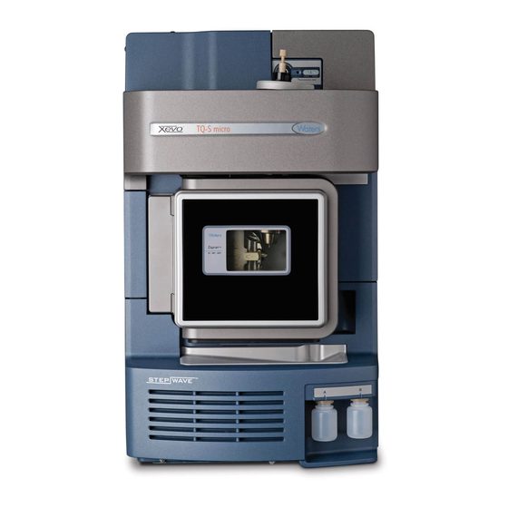
Optional ASAP probe For information on installing and removing the optional APGC, and ASAP probe, refer to the operator’s guide supplements supplied with them. You can also use the Xevo TQ-S micro with the following optional third-party sources: ® •... - Page 25 Uses and compatibility Xevo TQ-S micro shown with visor down, and visor up: Visor up TP03407 IntelliStart technology IntelliStart™ technology monitors LC/MS/MS performance and reports when the instrument is ready for use. The software automatically tunes and mass calibrates the instrument, displays performance readbacks, and enables simplified setup of the system for use in routine analytical and open access applications.
-
Page 26: Acquity Xevo Tq-S Micro Uplc/Ms Systems
The ACQUITY Xevo TQ-S micro UPLC/MS system can include an ACQUITY UPLC M-Class system and the Waters Xevo TQ-S micro fitted with either a Nanoflow source, or an ionKey source. If you are not using your instrument as part of an ACQUITY UPLC system, refer to the documentation for your LC system. - Page 27 Uses and compatibility ACQUITY system core components Core system components for each ACQUITY system are listed below: System Core components ACQUITY UPLC • Binary solvent manager • Sample manager • Column heater • UPLC detectors • Solvent tray • ACQUITY UPLC column •...
- Page 28 UPLC H-Class System Guide, ACQUITY UPLC I-Class System Guide, and Controlling Contamination in UPLC/MS and HPLC/MS Systems (part number 715001307). You can find the documents on http://www.waters.com; click Services and Support > Support Library. January 11, 2016, 715004599 Rev. B...
-
Page 29: Software And Data System
Uses and compatibility Xevo TQ-S micro with ACQUITY UPLC system: Sample organizer (optional) Solvent tray Column heater Xevo TQ-S micro Sample manager Binary solvent manager Software and data system MassLynx v4.1 software can control the mass spectrometer. See page 30 for more information about those applications. - Page 30 1 Specifications and Operating Modes MassLynx v4.1 MassLynx software acquires, analyzes, manages, and distributes mass spectrometry, ultraviolet (UV), evaporative light scattering, and analog data. OpenLynx TargetLynx application managers are included as standard software with MassLynx. See the MassLynx v4.1 user documentation and online Help for information about using MassLynx software.
-
Page 31: Ionization Techniques And Source Probes
Ionization techniques and source probes Note: Available source options can vary depending on the software used to operate the Xevo TQ-S micro. Refer to the MassLynx online Help for more information about supported sources. Electrospray ionization (ESI) In electrospray ionization (ESI), a strong electrical charge is applied to the eluent as it emerges from a nebulizer. -
Page 32: Nanoflow Source
1 Specifications and Operating Modes lamp drive assembly. The APPI lamp drive assembly comprises a UV lamp and a repeller electrode. In addition, a specially shaped, dual, APPI/APCI corona pin can be used. You can operate the source in APPI, APCI, or dual mode, which switches rapidly between APPI and APCI ionization modes. -
Page 33: Atmospheric Solids Analysis Probe (Asap)
Atmospheric pressure gas chromatography (APGC) The Waters APGC couples an Agilent GC with the Xevo TQ-S micro, making it possible to perform LC and GC analyses in the same system, without compromising performance. The APGC provides complementary information to the LCMS instrument, enabling analysis of compounds of low molecular weight and/or low-to-intermediate polarity. -
Page 34: Intellistart Fluidics System
1 Specifications and Operating Modes IntelliStart Fluidics system Functionality The IntelliStart Fluidics system is a solvent delivery system built into the mass spectrometer. It delivers sample or solvent directly to the MS probe in one of three ways: • From the LC column. •... -
Page 35: System Operation
IntelliStart Fluidics system System operation The software automatically controls solvent and sample delivery during auto-tuning, auto-calibration, and method development. The selector valve systematically makes connections between the fluidics components to carry out the operations processed by the software. You can set IntelliStart fluidics configuration requirements in the system console. You can edit the parameters, frequency, and extent of the automation. -
Page 36: Ion Optics
1 Specifications and Operating Modes Ion optics The mass spectrometer’s ion optics operate as follows: Samples from the LC or Intellistart fluidics system are introduced at atmospheric pressure into the ionization source. The ions pass through the sample cone into the vacuum system. The ions pass through the transfer optics (the ion guide) to the segmented quadrupole, where the are filtered according to their mass-to-charge ratios. - Page 37 MS operating modes MS operating modes: Operating mode Collision cell Pass all masses Resolving (scanning) Pass all masses Resolving (static) In MS mode, the instrument can acquire data at scan speeds as high as 20,000 Da/s. Use this mode for instrument tuning and calibration before MS/MS analysis. See the mass spectrometer’s online Help for further information.
-
Page 38: Ms/Ms Operating Modes
1 Specifications and Operating Modes MS/MS operating modes The following table shows the MS/MS operating modes, described in more detail in the following pages. MS/MS operating modes: Operating mode Collision cell Product (daughter) Static (at precursor Fragment precursor Scanning ion spectrum mass) ions and pass all masses... -
Page 39: Product (Daughter) Ion Mode
MS/MS operating modes Product (daughter) ion mode Product ion mode is the most commonly used MS/MS operating mode. You can specify an ion of interest for fragmentation in the collision cell, thus yielding structural information. Product ion mode: Collision cell Static (at precursor mass) Fragmenting Scanning... -
Page 40: Precursor (Parent) Ion Mode
RADAR In RADAR mode the Xevo TQ-S micro rapidly alternates between MRM and full scan MS acquisition modes. The instrument tracks target analytes with precision in MRM mode, while at the same time scanning (in MS mode) the background for all other components. - Page 41 MS/MS operating modes Typical application You typically use RADAR mode during method development prior to performing MRM or PICS to quantify known analytes in complex samples: • Drug metabolite and pharmacokinetic studies • Environmental, for example, pesticide and herbicide analysis •...
-
Page 42: Constant Neutral Loss Mode
1 Specifications and Operating Modes Constant neutral loss mode Constant neutral loss mode detects the loss of a specific neutral fragment or functional group from an unspecified precursor(s). The scans of MS1 and MS2 are synchronized. When MS1 transmits a specific precursor ion, MS2 “looks”... -
Page 43: Sample Inlet
You can deliver solutions by direct or combined infusion. Leak sensors Leak sensors in the Xevo TQ-S micro and the drip trays of the ACQUITY UPLC system continuously monitor system components for leaks. A leak sensor stops system flow when its optical sensor detects about 1.5 mL of accumulated, leaked liquid in its surrounding... -
Page 44: Rear Panel Connections
1 Specifications and Operating Modes Rear panel connections The following figure shows the rear panel locations of the connectors used to operate the instrument with external devices. Instrument rear panel: nano camera connection Event inputs and outputs Shielded Ethernet Waste bottle electrical connection Roughing pump control... -
Page 45: Preparing For Operation
Preparing for Operation This chapter describes how to start and shut down the instrument. Contents: Topic Page Starting the mass spectrometer ..............46 Preparing the IntelliStart Fluidics system............. 51 Rebooting the instrument................53 Leaving the mass spectrometer ready for operation ........54 January 11, 2016, 715004599 Rev. -
Page 46: Starting The Mass Spectrometer
2 Preparing for Operation Starting the mass spectrometer Notice: To avoid causing severe damage to the instrument, use compatible solvents only. For more details, refer to the following sources: • See page 257 for solvent information. • Appendix C of the ACQUITY UPLC System Operator’s Guide for solvent compatibility with ACQUITY devices. - Page 47 Starting the mass spectrometer Allow 3 minutes for the embedded PC (located inside the mass spectrometer) to initialize and to sound an alert indicating that the PC is ready. Tip: The power and status LEDs change as follows: • Each system instrument’s power LED shows green. •...
- Page 48 2 Preparing for Operation To evacuate (pump down) the mass spectrometer, follow the procedure below for MassLynx software. MassLynx software: Click IntelliStart in the MassLynx main window’s lower left-hand corner. Result: The mass spectrometer’s console appears. The mass spectrometer is in Standby mode.
-
Page 49: Verifying The Instrument's State Of Readiness
Starting the mass spectrometer Verifying the instrument’s state of readiness When the instrument is in good operating condition, the power and Operate LEDs show constant green. You can view any error messages in IntelliStart software. Monitoring the instrument LEDs Light-emitting diodes on the instrument indicate its operational status. Power LED The power LED, to the top, right-hand side of the mass spectrometer’s front panel, indicates when the instrument is powered-on or powered-off. -
Page 50: Running The Instrument At Different Flow Rates
Running the instrument at different flow rates The ACQUITY UPLC system runs at high flow rates. To optimize desolvation, and thus sensitivity, run the ACQUITY Xevo TQ-S micro system at appropriate gas flows and desolvation temperatures. IntelliStart software automatically sets these parameters when you enter a flow rate, according to the following table. -
Page 51: Preparing The Intellistart Fluidics System
Preparing the IntelliStart Fluidics system Preparing the IntelliStart Fluidics system For additional information, see page 246 Appendix Notice: To avoid damaging the mass spectrometer by accidentally spilling solvent on it, do not store large-volume solvent reservoirs on top of the instrument. Installing the reservoir bottles Use standard reservoir bottles (15-mL) for instrument setup and calibration. - Page 52 2 Preparing for Operation Warning: To avoid personal contamination with biohazards or toxic materials, and to avoid spreading contamination to uncontaminated surfaces, wear clean, chemical-resistant, powder-free gloves while installing reservoir bottles. To install the reservoir bottles: Remove the reservoir bottle caps. Screw the reservoir bottles onto the instrument, as shown below.
-
Page 53: Purging The Infusion Pump
Rebooting the instrument Purging the infusion pump Whenever you replace a solution bottle, purge the infusion pump with the solution that you are going to use next. See the mass spectrometer’s online Help for details. Requirement: Ensure that the end of the tubing is fully submerged in the solvent in the wash reservoir. -
Page 54: Leaving The Mass Spectrometer Ready For Operation
2 Preparing for Operation Tip: An audible alert sounds when the reboot sequence is complete. Leaving the mass spectrometer ready for operation Leave the mass spectrometer in Operate mode except in the following cases: • When performing routine maintenance • When changing the source •... -
Page 55: Changing The Mode Of Operation
For details about other Waters and third-party source options, refer to the documentation supplied with the source. Note: Available source options can vary depending on the software used to operate the Xevo TQ-S micro. Refer to the MassLynx online Help for more information about supported sources. Contents: Topic Page ESI mode ...................... -
Page 56: Esi Mode
3 Changing the Mode of Operation ESI mode The following sections explain how to install and remove an ESI probe. For further details on running ESI applications, see page Installing the ESI probe Required material Chemical-resistant, powder-free gloves Warning: To avoid personal contamination with biohazards or toxic materials, and to avoid spreading contamination to uncontaminated surfaces, wear clean, chemical-resistant, powder-free gloves while performing this procedure. - Page 57 ESI mode With the probe label facing you, carefully slide the ESI probe into the hole in the probe adjuster assembly, ensuring that the probe location dowel aligns with the location hole of the probe adjuster assembly. Probe label Probe locking ring Probe location dowel Location hole of the probe adjuster assembly...
- Page 58 3 Changing the Mode of Operation Warning: To avoid electric shock, do not use stainless steel tubing or stainless steel “finger tight” screws to connect the selector valve to the ESI probe; use the PEEK tubing and natural (beige) colored PEEK “finger tight” screws supplied with the instrument.
-
Page 59: Removing The Esi Probe
ESI mode Removing the ESI probe Required material Chemical-resistant, powder-free gloves Warning: To avoid personal contamination with biohazards or toxic materials, and to avoid spreading contamination to uncontaminated surfaces, wear clean, chemical-resistant, powder-free gloves while performing this procedure. The LC system connections, ESI probe, and source can be contaminated. -
Page 60: Esci Mode
3 Changing the Mode of Operation ESCi mode To run ESCi applications, you must fit an ESI probe and corona pin to the ESI/APCI/ESCi source enclosure. See “Installing the ESI probe” on page 56, “Installing the corona pin in the source” on page 101, and “IntelliStart Fluidics System”... -
Page 61: Installing The Ionsabre Ii Probe
APCI mode APCI mode: IonSABRE II probe Sample cone Corona pin Hot gas from the IonSABRE II probe passes between the sample cone and the corona pin, which is typically operated with a discharge current of 5 µA. Mobile phase molecules rapidly react with ions generated by the corona discharge to produce stable reagent ions. - Page 62 3 Changing the Mode of Operation To install the IonSABRE II probe: Prepare the instrument for working on the source (see page 97). With the probe label facing toward you, carefully slide the IonSABRE II probe into the hole in the probe adjuster assembly, ensuring that the probe location dowel aligns with the probe adjuster assembly location hole.
- Page 63 APCI mode • If you are replacing the tubing between the selector valve and the probe, minimize the length to reduce peak broadening. • When cutting the tubing to length, cut it squarely (that is, perpendicular to its horizontal axis). Install the corona pin (see page 101).
-
Page 64: Removing The Ionsabre Ii Probe
3 Changing the Mode of Operation Removing the IonSABRE II probe Required material Chemical-resistant, powder-free gloves Warning: To avoid personal contamination with biohazards or toxic materials, and to avoid spreading contamination to uncontaminated surfaces, wear clean, chemical-resistant, powder-free gloves while performing this procedure. -
Page 65: Combined Appi/Apci Source
Combined APPI/APCI source Combined APPI/APCI source Operate this optional, replacement source enclosure in APPI, APCI, or dual APPI/APCI mode. Dual-mode APPI/APCI performs rapid switching between ionization modes. APPI operation In atmospheric pressure photoionization (APPI) mode, the source is fitted with an IonSABRE II probe and the APPI lamp drive assembly is advanced into the source. -
Page 66: Apci Operation
3 Changing the Mode of Operation APCI operation The atmospheric pressure chemical ionization (APCI) mode produces singly charged protonated or deprotonated molecules for a large range of nonvolatile analytes. In APCI mode, the source is fitted with an APCI corona pin. Unused, the APPI lamp drive assembly is retracted from the source. -
Page 67: Dual-Mode Operation
Combined APPI/APCI source Dual-mode operation Dual-mode operation enables rapid switching between APPI and APCI ionization modes and allows high-throughput operations (for example, for sample screening). You replace the standard corona pin with a specially shaped APPI/APCI corona pin, so that the APPI lamp holder can be advanced into the source for dual operation. When the source is configured for dual operation in APCI mode, current is applied to the corona pin, but the repeller electrode is inactive. -
Page 68: The Combined Appi/Apci Source Components
3 Changing the Mode of Operation The combined APPI/APCI source components The combined APPI/APCI source comprises the standard IonSABRE II probe and a source enclosure with an APPI lamp drive incorporated. The combined APPI/APCI source enclosure: APPI lamp drive assembly Notice: To prevent damage to the corona pin and lamp assembly, ensure that the lamp assembly does not touch the corona pin when the source enclosure door is... - Page 69 Combined APPI/APCI source The UV lamp, which you ignite via a control in the MassLynx Tune window, provides a constant photon output. You vary the intensity of incident radiation upon the sample molecules by adjusting the distance between the UV lamp and probe tip. APPI lamp drive assembly inside the source enclosure: APPI lamp drive assembly...
-
Page 70: Installing The Combined Appi/Apci Source
3 Changing the Mode of Operation Installing the combined APPI/APCI source Required material Chemical-resistant, powder-free gloves Warning: To avoid personal contamination with biohazards or toxic materials, and to avoid spreading contamination to uncontaminated surfaces, wear clean, chemical-resistant, powder-free gloves while performing this procedure. -
Page 71: Removing The Ionsabre Ii Probe And Appi/Apci Source Enclosure
Combined APPI/APCI source Connect the HT cable to the instrument’s front panel connector. Notice: To prevent damage to the corona pin and lamp assembly, ensure that the lamp assembly does not touch the corona pin when the source enclosure door is closed. Install the IonSABRE II probe to the source, and ensure that it is working correctly (see page... -
Page 72: Nanoflow Source
3 Changing the Mode of Operation Fit the blanking plug to the pin’s mounting contact. NanoFlow source The NanoFlow source enclosure comprises the NanoFlow stage (for x-axis, y-axis, and z-axis adjustment), the sprayer-enclosure, and a microscope camera. NanoFlow source, stage and microscope camera: Microscope Camera Sprayer enclosure X, Y, Z stage... -
Page 73: Installing The Nanoflow Source
NanoFlow source The low flow rates involved with operating the NanoFlow source prohibit its use with the instrument’s solvent delivery system. Installing the NanoFlow source Required material Chemical-resistant, powder-free gloves Warning: To avoid personal contamination with biohazards or toxic materials, and to avoid spreading contamination to uncontaminated surfaces, wear clean, chemical-resistant, powder-free gloves while performing this procedure. - Page 74 NanoFlow source) and your sprayer. Tip: For details regarding how to fit each sprayer, see the corresponding reference: • Waters Universal NanoFlow Sprayer Installation and Maintenance Guide (part number 71500110107) • “Fitting a borosilicate glass capillary (nanovial)” on page 76 •...
- Page 75 NanoFlow source Connect the high-voltage cable to the instrument’s HV connection. High-voltage cable Tip: The NanoFlow stage contains a high-voltage interlock, so the capillary voltage (the voltage applied to the sprayer assembly) and the sampling cone voltage remain disabled until the sprayer is pushed fully forward in the source. 10.
-
Page 76: Fitting A Borosilicate Glass Capillary (Nanovial)
3 Changing the Mode of Operation Fitting a borosilicate glass capillary (nanovial) Required materials • Chemical-resistant, powder-free gloves • Needle-nose pliers • Borosilicate glass capillary ® • Fused silica syringe needle or GELoader • Fused silica cutter Warning: To avoid lacerations, puncture injuries, and possible contamination with biohazardous and toxic samples, do not touch the sharp end of the capillary. - Page 77 NanoFlow source Unscrew the union from the end of the sprayer assembly. Capillary Union Remove the existing capillary from the sprayer. Carefully remove the new borosilicate glass capillary from its case by lifting vertically while pressing on the foam with two fingers. Foam Capillary Load sample into the capillary using a fused silica syringe needle or a GELoader...
- Page 78 3 Changing the Mode of Operation Recommendation: When using a GELoader tip, break the glass capillary in half, scoring it with a fused silica cutter so that the GELoader can reach the capillary’s tip. Thread the knurled nut and approximately 5 mm of conductive elastomer over the blunt end of the capillary.
-
Page 79: Positioning The Borosilicate Glass Capillary Tip
NanoFlow source Notice: To prevent the capillary tip from colliding with the cone or the side of the source, adjust the sprayer tip position before you push the sprayer inside the NanoFlow source enclosure. 15. Carefully push the stage back into the NanoFlow source enclosure, using the stop and handle. -
Page 80: Ionkey Source
3 Changing the Mode of Operation ionKey source The ionKey source integrates UPLC separation into the source of the mass spectrometer. For a complete description, see “ionKey source” on page The following sections explain how to install or remove an ionKey source. For further information, see the ACQUITY UPLC M-Class System Guide (part number 715003588) and the ionKey/MS System Guide (part number 715004028). - Page 81 ionKey source Warning: To avoid personal contamination with biohazards or toxic materials, and to avoid spreading contamination to uncontaminated surfaces, wear clean, chemical-resistant, powder-free gloves while performing this procedure. The source components can be contaminated. Warning: To avoid electric shock, prepare the instrument for work performed on its source before beginning this procedure.
- Page 82 3 Changing the Mode of Operation ionKey source connections: Options cable High voltage cable Data/power cable to PSPI connector on µSample manager Fluid inlet line Fluid infusion line Fluid waste line Optional post-column addition (PCA) line Connect the data/power cable to the PSPI connector on the rear of the µSample manager, and use a screwdriver to firmly tighten the connector screws.
- Page 83 ionKey source Source connections to mass spectrometer: High voltage cable Options cable Data/power cable to PSPI connector on µSample manager Connect the high voltage cable (white) to the high voltage supply outlet on the mass spectrometer. Connect the options cable (blue) to the options port on the mass spectrometer. January 11, 2016, 715004599 Rev.
- Page 84 3 Changing the Mode of Operation Identify each fluid line by the part numbers printed on their shrink-wrap tubing. ionKey tubing assemblies: Part Number Order Number Description 430004188 700010399 Inlet tube 430004190 700010400 Infusion tube 430004212 700010401 Waste tube 430004476 700010470 Optional, post-column addition tube Fluid line aperture:...
-
Page 85: Installing Ionkey Source Software
13. Connect the waste line to a suitable waste container. Installing ionKey source software If you are installing an ionKey source on your Xevo TQ-S micro for the first time, you must install the appropriate MassLynx software SCN and the ACQUITY UPLC M-Class driver pack. -
Page 86: Installing The Camera In The Ionkey Source
3 Changing the Mode of Operation Installing the camera in the ionKey source To install the camera software for the ionKey source: Connect the camera cable from the video output connector on the mass spectrometer’s rear panel to the video-to-USB converter box. Notice: To avoid damaging the video converter, make sure the workstation is powered-off before connecting the converter to the workstation in the next step. - Page 87 ionKey source See the ACQUITY UPLC M-Class documentation for further information about installing the source holder on the M-Class cart, and securing the source enclosure to the holder. See M-Class Cart Universal Source Holder (part number 715004884) for further information about installing and using the universal source holder on the M-Class cart, and securing the source enclosure to the holder.
- Page 88 3 Changing the Mode of Operation Swing open the ionKey source enclosure unit from the source mounting on the mass spectrometer. 10. Disconnect the high voltage cable (white) from the high voltage supply outlet on the mass spectrometer. 11. Disconnect the options cable (blue) from the options port on the mass spectrometer. 12.
-
Page 89: Maintenance Procedures
Maintenance Procedures This chapter provides the maintenance guidelines and procedures necessary to maintain the instrument’s performance. Keep to a maintenance schedule, and perform maintenance as required and described in this chapter. Contents: Topic Page Maintenance schedule................... 91 Spare parts ....................93 Troubleshooting with Connections INSIGHT.......... - Page 90 4 Maintenance Procedures Contents: Topic Page Cleaning the IonSABRE II probe tip............166 Replacing the IonSABRE II probe sample capillary........167 Cleaning or replacing the corona pin............172 Replacing the IonSABRE II probe heater ............ 174 Replacing the ion block source heater ............177 Replacing the source assembly seals ............
-
Page 91: Maintenance Schedule
Maintenance schedule Maintenance schedule The following table lists periodic maintenance schedules that ensure optimum instrument performance. The maintenance frequencies shown apply to instruments that normally receive moderate use. Maintenance schedule: Procedure Frequency For information... Clean the instrument case. As required. page 108. - Page 92 4 Maintenance Procedures Maintenance schedule: Procedure Frequency For information... Clean the IonSABRE II probe tip. When sensitivity page 166. (Options using the IonSABRE II decreases to unacceptable probe only.) levels or when significant chemical interference is present. Replace the IonSABRE II probe When sensitivity page 167.
-
Page 93: Spare Parts
Spare parts Replace only spare parts, which are the parts mentioned in this document. For details ® about spare parts, use the Waters Quality Parts Locator on the Waters Web site’s Services & Support page. January 11, 2016, 715004599 Rev. B... -
Page 94: Troubleshooting With Connections Insight
Connections INSIGHT is an “intelligent” device management (IDM) Web service that enables Waters to provide proactive service and support for the ACQUITY UPLC system. To use Connections INSIGHT, you must install its service agent software on your workstation. In a client/server system, the service agent must also be installed on the computer from which you control the system. -
Page 95: Safety And Handling
Safety and handling Safety and handling Bear in mind the following safety considerations when performing maintenance procedures: Warning: To avoid personal contamination, always wear chemical-resistant, powder-free gloves while handling instrument components. The components can be contaminated with biohazards or toxic materials. - Page 96 4 Maintenance Procedures Notice: To avoid damaging the iKey: • Handle it with care. The component parts are fragile. • For recommendations regarding the maximum pressure to subject the device to, see the iKey Separation Device Care and Use Manual (part number 720004897EN).
-
Page 97: Preparing The Instrument For Operations On Or Inside Its Source
In the Instrument Console, click Stop Flow to stop the LC flow or, if column flow is required, divert the LC flow to waste as follows: In the Instrument Console system tree, expand Xevo TQ-S micro, Interactive Fluidics. Click Control Select Waste as the flow state. -
Page 98: Removing And Refitting The Source Enclosure
4 Maintenance Procedures Removing and refitting the source enclosure The optional combined APPI/APCI, NanoFlow and ionKey sources are supplied as a complete source enclosure. To fit them, you must first remove the standard source enclosure. Removing the source enclosure from the instrument Required material Chemical-resistant, powder-free gloves Warning:... - Page 99 Removing and refitting the source enclosure Using both hands, grasp the source enclosure and lift it vertically off the two supporting studs on the source adaptor housing. Cable storage positions Supporting stud TP03164 Source enclosure Store the cables neatly by plugging them into the cable-storage positions on the rear of the source enclosure.
-
Page 100: Fitting The Source Enclosure To The Instrument
4 Maintenance Procedures Fitting the source enclosure to the instrument Required material Chemical-resistant, powder-free gloves Warning: To avoid personal contamination with biologically hazardous, or toxic materials, and to avoid spreading contamination to uncontaminated surfaces, wear clean, chemical-resistant, powder-free gloves when working with the source components. -
Page 101: Installing And Removing The Corona Pin
Installing and removing the corona pin Installing and removing the corona pin For ESCi, APCI, and dual-mode APCI/APPI operation, you must fit a corona pin. Installing the corona pin in the source Required material Chemical-resistant, powder-free gloves Warning: To avoid personal contamination with biologically hazardous, or toxic materials, and to avoid spreading contamination to uncontaminated surfaces, wear clean, chemical-resistant, powder-free gloves while performing this procedure. - Page 102 4 Maintenance Procedures Remove the blanking plug from the corona pin mounting contact. Tip: Store the blanking plug in a safe location. Corona pin mounting contact: Corona pin mounting contact blanking plug Warning: To avoid puncture wounds, handle the corona pin with care; the tip is sharp.
-
Page 103: Removing The Corona Pin From The Source
Installing and removing the corona pin Close the source enclosure. Look through the source window, and use the vernier probe adjuster to position the probe tip so that it is pointing approximately midway between the tips of the sample cone and corona pin. Removing the corona pin from the source Required material Chemical-resistant, powder-free gloves... -
Page 104: Operating The Source Isolation Valve
4 Maintenance Procedures Operating the source isolation valve You must close the source isolation valve to isolate the source from the instrument vacuum system for certain maintenance procedures. Required material Chemical-resistant, powder-free gloves Warning: To avoid personal contamination with biohazards or toxic materials, and to avoid spreading contamination to uncontaminated surfaces, wear clean, chemical-resistant, powder-free gloves when working with the source components. - Page 105 Operating the source isolation valve Close the source isolation valve by moving its handle counterclockwise, to the vertical position. Isolation valve handle in closed position Warning: To avoid personal contamination with biohazards or toxic materials, and to avoid spreading contamination to uncontaminated surfaces, wear clean, chemical-resistant, powder-free gloves when working with the source components.
- Page 106 4 Maintenance Procedures Isolation valve handle in open position Close the source enclosure. January 11, 2016, 715004599 Rev. B...
-
Page 107: Removing O-Rings And Seals
Removing O-rings and seals Removing O-rings and seals When performing certain maintenance procedures, you must remove O-rings or seals from instrument components. An O-ring removal kit can be purchased separately. O-ring removal kit: Tool 1 Tool 2 Notice: To avoid scratching the O-ring or seal, take care while using the removal tools to remove it from components. -
Page 108: Cleaning The Instrument Case
4 Maintenance Procedures Cleaning the instrument case Notice: To avoid damaging the instrument, do not use abrasives or solvents to clean the instrument’s case. Use a soft cloth, dampened with water, to clean the outside surfaces of the instrument. Emptying the exhaust trap bottle Inspect the exhaust trap bottle in the instrument’s exhaust line daily, and empty it before it is more than 10% full. - Page 109 Emptying the exhaust trap bottle Required material Chemical-resistant, powder-free gloves To empty the nitrogen exhaust trap bottle: In the MassLynx software’s MS Console, click Stop Flow Pull the source enclosure release (located at the bottom, right-hand side) outward, and swing open the enclosure. Warning: To avoid personal contamination with biologically hazardous, or toxic materials, wear clean, chemical-resistant,...
-
Page 110: Gas Ballasting The Roughing Pump
4 Maintenance Procedures Gas ballasting the roughing pump The roughing pump draws large quantities of solvent vapors. The vapors tend to condense in the pump oil, diminishing pumping efficiency. Gas ballasting purges condensed contaminants from the oil. Note: This procedure is not required for an oil-free roughing pump. Roughing pump: Exhaust port flange Oil filler plug... - Page 111 Gas ballasting the roughing pump Notice: To avoid shortening the oil life and pump life, routinely gas ballast the roughing pump according to the guidelines below. Gas ballast the roughing pump when these conditions apply: • With ESI operation, once a week •...
-
Page 112: Checking The Roughing Pump Oil Level
4 Maintenance Procedures Warning: To avoid burn injuries, take great care while working with the roughing pump; it can be hot. Warning: To gas ballast the roughing pump: Move the gas ballast valve handle on the pump counterclockwise, from the horizontal position to the vertical position. -
Page 113: Adding Oil To The Roughing Pump
Adding oil to the roughing pump The roughing pump oil level appears in the roughing pump’s oil level sight glass. Check the oil level weekly; you must maintain the oil level at or near the indicated maximum level when the pump is not operating. Requirement: You must check the oil level while the roughing pump is running. -
Page 114: Cleaning The Source Components
4 Maintenance Procedures Using the funnel, add Anderol vacuum oil, type GS 495, into the oil filler aperture until the oil reaches the oil level sight glass MAX level. Ensure that the O-ring on the oil filler plug is clean and properly seated. Notice: To avoid oil leakage, and consequent damage to the pump, when refitting the oil filler plug, ensure that:... -
Page 115: Cleaning The Sampling Cone Assembly
Cleaning the sampling cone assembly Cleaning the sampling cone assembly You can remove the sampling cone assembly (the sample cone, O-ring, and cone gas nozzle) for cleaning without venting the instrument. Removing the sampling cone assembly from the source Required material Chemical-resistant, powder-free gloves Warning: To avoid personal contamination with biohazards or toxic... - Page 116 4 Maintenance Procedures To remove the sampling cone assembly from the source: Close the source isolation valve (see page 104). Grasp the cone gas nozzle handle, and use it to rotate the sampling cone assembly 90 degrees, moving the handle from the vertical to the horizontal position. Sampling cone assembly Cone gas nozzle...
-
Page 117: Disassembling The Sampling Cone Assembly
Cleaning the sampling cone assembly Disassembling the sampling cone assembly Required material • Chemical-resistant, powder-free gloves • Combined 2.5-mm Allen wrench and cone extraction tool Warning: To avoid personal contamination with biohazards or toxic materials, and to avoid spreading contamination to uncontaminated surfaces, wear clean, chemical-resistant, powder-free gloves when working with the sampling cone assembly. - Page 118 4 Maintenance Procedures Insert the collar in the sample cone. Notice: To avoid damaging the fragile sample cone, do not place it on its tip; instead, place it on its flanged base. Rotate the tool and collar counter-clockwise and then lift them to remove the sample cone from the cone gas nozzle.
- Page 119 Cleaning the sampling cone assembly Remove the O-ring from the sample cone. Cone gas nozzle Cone gas nozzle handle O-ring Warning: To avoid spreading contamination, dispose of the O-ring or seal in accordance with local environmental regulations. If the O-ring shows signs of deterioration or damage, dispose of it in accordance with local environmental regulations.
-
Page 120: Cleaning The Sample Cone And Cone Gas Nozzle
4 Maintenance Procedures Cleaning the sample cone and cone gas nozzle Required materials • Chemical-resistant, powder-free gloves. • Appropriately sized glass vessels in which to completely immerse components when cleaning. Use only glassware not previously cleaned with surfactants. • HPLC-grade (or better) methanol. •... - Page 121 Cleaning the sampling cone assembly Rinse the components by immersing them in separate glass vessels containing water and then place the vessels in the ultrasonic bath for 20 minutes. Remove any residual water from the extraction cone by immersing it in a glass vessel containing methanol and then place the vessel in the ultrasonic bath for 10 minutes.
-
Page 122: Assembling The Sampling Cone Assembly
4 Maintenance Procedures Assembling the sampling cone assembly Required material Clean, chemical-resistant, powder-free gloves Notice: • To avoid recontaminating the sampling cone assembly, wear clean chemical-resistant, powder-free gloves during this procedure. • To avoid damaging the fragile sample cone, do not place it on its tip; instead, place it on its flanged base. -
Page 123: Fitting The Sampling Cone Assembly To The Source
Cleaning the sampling cone assembly Fitting the sampling cone assembly to the source Required material Chemical-resistant, powder-free gloves Warning: To avoid personal contamination with biohazards or toxic materials, and to avoid spreading contamination to uncontaminated surfaces, wear clean, chemical-resistant, powder-free gloves when working with the source components. - Page 124 4 Maintenance Procedures To fit the sampling cone assembly to the source: Ensure that the source isolation valve is in the closed position (see page 104). Hold the sampling cone assembly so that the cone gas nozzle handle is oriented horizontally and at the top, and then slide the sampling cone assembly into the ion block assembly.
-
Page 125: Cleaning The Ion Block Assembly
Cleaning the ion block assembly Cleaning the ion block assembly Clean the ion block assembly if cleaning the sample cone and cone gas nozzle fails to increase signal sensitivity. Removing the ion block assembly from the source assembly Required materials •... - Page 126 4 Maintenance Procedures Use the combined 2.5-mm Allen wrench and cone extraction tool to unscrew the 4, captive, ion block assembly securing screws. Screws securing the Ion block assembly Remove the ion block assembly from the PEEK ion block support. PEEK ion block support Ion block assembly January 11, 2016, 715004599 Rev.
-
Page 127: Disassembling The Source Ion Block Assembly
Cleaning the ion block assembly Disassembling the source ion block assembly Required materials • Chemical-resistant, powder-free gloves • Combined 2.5-mm Allen wrench and cone extraction tool • O-ring removal kit To disassemble the ion block assembly: Warning: The ion block assembly can be contaminated with biohazardous and/or toxic materials. - Page 128 4 Maintenance Procedures Use the combined 2.5-mm Allen wrench and cone extraction tool to loosen the 2 captive screws securing the ion block cover plate. Ion block cover plate securing screw Ion block cover plate Remove the ion block cover plate. Grasp the isolation valve, and pull it out of the ion block.
- Page 129 Cleaning the ion block assembly Use the O-ring removal kit to carefully remove the isolation valve O-ring (see page 107). Warning: The isolation valve O-ring can be contaminated with biohazardous and/or toxic materials. Dispose of it according to local environmental regulations. If the isolation valve O-ring shows signs of deterioration or damage, dispose of it in accordance with local environmental regulations.
- Page 130 4 Maintenance Procedures Notice: To avoid damaging the heater cartridge assembly wires, do not bend or twist them when removing the assembly and ceramic heater mounting block from the ion block. 10. Carefully remove the PEEK terminal block and ceramic heater mounting block, complete with heater cartridge assembly, from the ion block.
- Page 131 Cleaning the ion block assembly 11. Use the O-ring removal kit to carefully remove the cover seal from the ion block (see also page 107). Cover seal Cone gas O-ring 12. Use the O-ring removal kit to carefully remove the cone gas O-ring from the ion block.
-
Page 132: Cleaning The Ion Block Components
4 Maintenance Procedures Cleaning the ion block components Required materials • Chemical-resistant, powder-free gloves. • Appropriately sized glass vessels in which to completely immerse components when cleaning. Use only glassware not previously cleaned with surfactants. • HPLC-grade (or better) methanol. •... -
Page 133: Assembling The Source Ion Block Assembly
Cleaning the ion block assembly If you used formic acid in the cleaning solution, do as follows: Rinse the components by immersing them separately in glass vessels containing water and then placing the vessels in the ultrasonic bath for 20 minutes. Dry the components by immersing them in separate glass vessels containing methanol and then placing the vessels in the ultrasonic bath for 10 minutes. - Page 134 4 Maintenance Procedures To assemble the ion block assembly: Notice: • To avoid recontaminating the ion block assembly, wear clean, chemical-resistant, powder-free gloves during this procedure. • To avoid damaging the heater cartridge assembly wires, do not bend or twist them when fitting the assembly and ceramic heater mounting block to the ion block.
-
Page 135: Fitting The Ion Block Assembly To The Source Assembly
Cleaning the ion guide assembly Fitting the ion block assembly to the source assembly Required materials • Chemical-resistant, powder-free gloves • Combined 2.5-mm Allen wrench and cone extraction tool To fit the ion block assembly to the source assembly Warning: The source components can be contaminated with biohazardous and/or toxic materials. -
Page 136: Removing The Pumping Block Assembly And Ion Guide Assembly From The Instrument
4 Maintenance Procedures Removing the pumping block assembly and ion guide assembly from the instrument Required materials • Chemical-resistant, powder-free gloves • 3-mm Allen wrench Warning: To avoid personal contamination with biohazards or toxic materials, and to avoid spreading contamination to uncontaminated surfaces, wear clean, chemical-resistant, powder-free gloves when working with the source components. -
Page 137: Removing The Ion Guide Assembly And Differential Aperture From The Pumping Block Assembly
Cleaning the ion guide assembly Ion guide assembly Securing screws Pumping block Housing assembly Notice: To avoid damaging the ion guide assembly when removing the pumping block assembly from the instrument, do not grasp the ion guide by its metal lens plates. Instead, grasp the circuit boards on the top and bottom of the device. -
Page 138: Removing The Differential Aperture Support And The Differential Aperture From The Ion Guide Assembly
4 Maintenance Procedures To remove the ion guide assembly and differential aperture support from the pumping block assembly: Use the 3-mm Allen wrench to unscrew and remove the two screws securing the differential aperture and the ion guide assembly boards to the pumping block assembly. - Page 139 Cleaning the ion guide assembly • Flat-head screwdriver Warning: To avoid personal contamination with biohazards or toxic materials, and to avoid spreading contamination to uncontaminated surfaces, wear clean, chemical-resistant, powder-free gloves when working with the source components. To remove the differential aperture support and the differential aperture from the ion guide assembly: Place the ion guide assembly with differential aperture on to a clean flat surface.
-
Page 140: Cleaning The Differential Aperture
To clean the differential aperture: Place the differential aperture in the glass vessel. Add Waters MS Cleaning Solution or 1:1 methanol/water to the vessel until the differential aperture is immersed completely. Place the vessel containing the differential aperture in the ultrasonic bath for 20 minutes. -
Page 141: Cleaning The Ion Guide Assembly
Tip: You can reuse Waters MS Cleaning Solution for one subsequent cleaning. Fill the vessel with deionized water, to rinse the differential aperture, and then discard the water. - Page 142 4 Maintenance Procedures Notice: To avoid damaging the ion guide assembly, use only methanol and water as solvents. Do not use acetone, chlorinated solvents, or acid. To clean the ion guide assembly: Bend a PEEK or PTFE tube into a hook shape. Insert one end of the hook into one of the holes in the ion guide’s rear circuit board carrier.
-
Page 143: Fitting The Differential Aperture And The Differential Aperture Support Onto The Ion Guide Assembly
Cleaning the ion guide assembly Add 1:1 methanol/water to the glass vessel until the ion guide assembly is immersed completely. Place the vessel in the ultrasonic bath for 30 minutes. Notice: To avoid recontaminating the ion guide assembly, wear clean, chemical-resistant, powder-free gloves for the rest of this procedure. -
Page 144: Fitting The Ion Guide Assembly And Differential Aperture Onto The Pumping Block Assembly
4 Maintenance Procedures To fit the differential aperture and the differential aperture support onto the ion guide assembly: Check the condition of the O-ring between the differential aperture and the differential aperture support. If necessary, use the O-ring removal kit to remove and replace the O-ring. -
Page 145: Fitting The Pumping Block Assembly And Ion Guide Assembly Onto The Instrument
Cleaning the ion guide assembly To fit the ion guide assembly and differential aperture onto the pumping block assembly: Check the seals on the pumping block assembly to make sure they are not damaged. Place the ion guide assembly and differential aperture onto the two studs of the pumping block assembly. -
Page 146: Replacing The Esi Probe Tip And Gasket
4 Maintenance Procedures Replacing the ESI probe tip and gasket Maintaining the ESI probe involves replacing the following components of the probe when required: Part number Name 700004207 ESI probe tip 700004208 Nickel gasket 700000640 PTFE liner tube 700000343 Ferrule 700000969 Conductive sleeve 700004206... - Page 147 Replacing the ESI probe tip and gasket Warning: To avoid puncture wounds, handle the probe with care; the ESI probe tip is sharp. Warning: To avoid eye injury from the sharp capillary, wear safety goggles when performing the leak test. To replace the ESI probe tip and gasket: Remove the ESI probe from the source (see page...
- Page 148 4 Maintenance Procedures Remove the nickel gasket from the probe tip. Nickel gasket Warning: To avoid spreading biohazardous, toxic, or corrosive contamination, dispose of the probe tip and nickel gasket in accordance with local environmental regulations. They can be contaminated with biohazards or toxic materials. Dispose of the nickel gasket in accordance with local environmental regulations.
- Page 149 Replacing the ESI probe tip and gasket Carefully slide the probe tip onto the ESI probe, ensuring that the capillary feeds through the stainless steel tube inside the probe tip. Screw the probe tip onto the ESI probe assembly. Tighten the probe tip using the 7-mm wrench and the 10-mm wrench, as shown in the following figure: 7-mm wrench 10-mm wrench...
-
Page 150: Replacing The Esi Probe Capillary
4 Maintenance Procedures Replacing the ESI probe capillary Replace the stainless steel ESI probe capillary if it becomes irreversibly blocked, or if it becomes contaminated or damaged. Required materials • Chemical-resistant, powder-free gloves • Combined 2.5-mm Allen wrench and cone extraction tool •... - Page 151 Replacing the ESI probe tip and gasket To remove the existing capillary: Remove the probe from the source enclosure (see page 59). Use the 2.5-mm Allen wrench to loosen the three captive screws securing the probe’s end cover in place, and then remove the end cover and rubber gasket. Tip: The end cover is secured by captive screws that you need not remove from the end cover of the probe.
- Page 152 4 Maintenance Procedures Unscrew and remove the ESI probe tip by holding the probe shaft steady using the 7-mm wrench and unscrewing the probe tip using the 10-mm wrench, as shown in the following figure: 7-mm wrench 10-mm wrench Probe shaft Probe tip Remove the nickel gasket from the probe tip.
- Page 153 Replacing the ESI probe tip and gasket Dispose of the nickel gasket in accordance with local environmental regulations. Warning: To avoid puncture wounds, handle the sharp capillary with care. Remove the slide port assembly from the probe assembly by pulling the PEEK union.
- Page 154 4 Maintenance Procedures 10. Loosen the lock nut at the base of the PEEK union using both the 7-mm and 8-mm wrenches. Capillary 7-mm wrench Slide port 8-mm wrench Lock nut PEEK union Note: Use the 8-mm wrench to hold the PEEK union while you loosen the lock nut using the 7-mm wrench.
- Page 155 Replacing the ESI probe tip and gasket 11. Unscrew and remove the PEEK union from the slide port using both the 7-mm and 8-mm wrenches. 8-mm wrench PEEK union 7-mm wrench Slide port Sample capillary Note: Hold the slide port steady by attaching the 7-mm wrench to the flattened grooves on the slide port’s collar, as shown in the figure.
- Page 156 4 Maintenance Procedures To install the new capillary Slide the new ferrule onto the new PTFE liner tube so that approximately 2 mm of liner tubing is exposed beyond the tapered end of the ferrule. Note: Ensure that the ferrule is oriented as shown in the figure. Liner tube Ferrule Slide the PTFE liner tube and ferrule assembly onto the new capillary.
- Page 157 Replacing the ESI probe tip and gasket Pull the capillary through the slide port so that the end of the capillary aligns with the end of the PTFE liner tube, as shown in the figure. Capillary Liner tube Liner tube and capillary ends aligned Ferrule Insert the capillary and liner tube fully into the PEEK union, ensuring that the...
- Page 158 4 Maintenance Procedures Feed the capillary through the liner tube and PEEK union, to expose approximately 50 mm of capillary on the opposite side of the union. Slide port Liner tube PEEK union Capillary (approximately 50 mm exposed) Screw the PEEK union onto the slide port, ensuring that the union is not fully tightened.
- Page 159 Replacing the ESI probe tip and gasket 10. Insert the red PEEK tubing into the probe inlet connector, to expose approximately 25 mm of tubing beyond the narrow end of the inlet connector. Red PEEK tubing Probe inlet connector 11. Using the end of the red PEEK tubing, push the capillary into the PEEK union until the red PEEK tubing is inserted as far as possible into the PEEK union.
- Page 160 4 Maintenance Procedures 13. Finger-tighten the PEEK union onto the slide port, and then, using the 7-mm and 8-mm wrenches, tighten by an additional quarter-turn. 7-mm wrench Capillary Lock nut Slide port 8-mm wrench PEEK union Probe inlet connector Red PEEK tubing 14.
- Page 161 Replacing the ESI probe tip and gasket 15. Slide the new conductive liner tube and knurled nut onto the capillary, and then tighten the knurled nut. Knurled nut Conductive liner tube Slide port PEEK union Probe inlet connector Red PEEK tubing Warning: To avoid eye injury from high-pressure liquid jet spray, wear safety goggles when performing the leak test.
- Page 162 4 Maintenance Procedures 18. Carefully thread the capillary through the probe assembly until the slide port and PEEK union assembly reach the top of the probe assembly. PEEK union Slide port Capillary Probe cable ESI probe assembly 19. Push the slide port and PEEK union assembly into the probe assembly so that the dowel on the slide port is fully engaged in the locating slot at the head of the probe assembly.
- Page 163 Replacing the ESI probe tip and gasket 20. Fit the nebulizer adjuster knob to the PEEK union, and fully tighten the knob. Probe cables ESI probe Nebulizer adjuster knob 21. Fit the end cover and gasket around the nebulizer adjuster knob. Important: Ensure that the end cover’s drip point is orientated so that, when viewed face-on, the probe’s warning label is directly to the left-hand side of the drip...
- Page 164 4 Maintenance Procedures 22. Secure the end cover and gasket to the ESI probe by tightening the three captive screws using the 2.5-mm Allen wrench. Nickel gasket ESI probe tip Stainless steel tube 23. Insert the new nickel gasket into the ESI probe tip so that the gasket is seated around the narrow, stainless steel tube inside the probe tip.
- Page 165 Replacing the ESI probe tip and gasket 26. Tighten the probe tip using the 7-mm wrench and the 10-mm wrench, as shown in the following figure: 7-mm wrench 10-mm wrench Probe shaft Probe tip Important: To avoid gas leakage, fully tighten the probe tip. 27.
-
Page 166: Cleaning The Ionsabre Ii Probe Tip
Clean the IonSABRE II probe tip when you detect buffer buildup on the probe tip or when the signal intensity weakens. See the mass spectrometer’s online Help for further details. To clean the IonSABRE II probe tip: On the Instrument Console system tree, click Xevo TQ-S micro > Manual optimization. On the Manual Optimization page, click to stop the liquid flow. -
Page 167: Replacing The Ionsabre Ii Probe Sample Capillary
Replacing the IonSABRE II probe sample capillary Replacing the IonSABRE II probe sample capillary Replace the stainless steel sample capillary in the IonSABRE II probe if it becomes blocked and you cannot clear it, or if it becomes contaminated or damaged. Removing the existing capillary Required materials •... - Page 168 4 Maintenance Procedures Remove the end cover and gasket. Nebulizer adjuster knob Gasket End-cover Unscrew and remove the nebulizer adjuster knob. Remove the PEEK union/UNF coupling assembly and capillary from the probe. Tip: The PEEK union used with the IonSABRE II probe is notched on one of its flats, a feature that distinguishes it from the PEEK union used with the ESI probe (see “Replacing the ESI probe sample capillary”...
-
Page 169: Installing The New Capillary
Replacing the IonSABRE II probe sample capillary Unscrew the finger-tight PEEK union from the UNF coupling. Ferrule Remove the ferrule from the capillary. 10. Remove the capillary from the UNF coupling. Warning: To avoid spreading contamination, dispose of the capillary and ferrule in accordance with local environmental regulations. - Page 170 4 Maintenance Procedures Warning: To avoid personal contamination with biohazards or toxic materials, and to avoid spreading contamination to uncontaminated surfaces, wear clean, chemical-resistant, powder-free gloves when working with the probe and source components. To install the new capillary: Use the sharp knife or PEEK tubing cutter to cut a piece of red PEEK tubing approximately 60 cm (24 inches) long.
- Page 171 Replacing the IonSABRE II probe sample capillary Insert the capillary in the PEEK union, and ensure that it is fully seated. Screw the UNF coupling into the PEEK union, finger-tight only. Gently tug on the capillary, testing to ensure that it stays in place. Use the 7-mm wrench to tighten the locknut against the PEEK union.
-
Page 172: Cleaning Or Replacing The Corona Pin
4 Maintenance Procedures 16. Fit the nebulizer adjuster knob to the PEEK union/UNF coupling assembly. 17. Finger-tighten the nebulizer adjuster knob onto the probe assembly. 18. Fit the probe gasket and end-cover to the probe assembly. 19. Use the combined 2.5-mm Allen wrench and cone extraction tool to fit and tighten the 3 screws retaining the probe end-cover. - Page 173 Cleaning or replacing the corona pin • Corona pin Warning: To avoid personal contamination with biohazards or toxic materials, and to avoid spreading contamination to uncontaminated surfaces, wear clean, chemical-resistant, powder-free gloves when working with the probe and source components. Warning: To avoid burn injuries, take great care while performing this procedure;...
-
Page 174: Replacing The Ionsabre Ii Probe Heater
4 Maintenance Procedures Replacing the IonSABRE II probe heater Replace the IonSABRE II probe heater if it fails to heat the probe. Removing the IonSABRE II probe heater Required material Chemical-resistant, powder-free gloves Warning: To avoid personal contamination with biohazards or toxic materials, and to avoid spreading contamination to uncontaminated surfaces, wear clean, chemical-resistant, powder-free gloves when working with the probe and source components. - Page 175 Replacing the IonSABRE II probe heater Notice: To avoid damaging the probe heater’s electrical connections, do not twist the heater when removing it from the probe assembly. Gripping the probe heater as shown, carefully pull it off the probe assembly. Probe heater Warning: To avoid spreading contamination, dispose of the probe...
-
Page 176: Fitting The New Ionsabre Ii Probe Heater
4 Maintenance Procedures Fitting the new IonSABRE II probe heater Required materials • Chemical-resistant, powder-free gloves • IonSABRE II probe heater Notice: To avoid damaging the probe heater’s electrical connections, capillary sleeve, or capillary, take great care when fitting the heater over the capillary sleeve. -
Page 177: Replacing The Ion Block Source Heater
Replacing the ion block source heater Replacing the ion block source heater Replace the ion block source heater if it fails to heat when the instrument is pumped down (evacuated). Required materials • Chemical-resistant, powder-free gloves • Needle-nose pliers • Combined 2.5-mm Allen wrench and cone extraction tool •... - Page 178 4 Maintenance Procedures Use the combined 2.5-mm Allen wrench and cone extraction tool to loosen the 2 captive screws securing the ion block cover plate. Ion block cover plate securing screw Ion block cover plate Remove the ion block cover plate. Use the combined 2.5-mm Allen wrench and cone extraction tool to remove the 2 screws securing the heater wires to the PEEK terminal block.
- Page 179 Replacing the ion block source heater Use the needle-nose pliers to carefully swing the ring terminal tags out of the terminal block. Ring terminal tag Use the needle-nose pliers to gently grasp the heat-shrink tubing on the heater cartridge assembly and slide the assembly out of the ion block. Heat-shrink tubing Heater cartridge assembly Dispose of the heater cartridge assembly.
-
Page 180: Replacing The Source Assembly Seals
4 Maintenance Procedures Use the needle-nose pliers to gently grasp the heat-shrink tubing on the new heater cartridge assembly and slide the assembly into the ion block. Notice: To avoid a short circuit to the ion block cover, ensure that the 2 heater cartridge ring tags are pushed fully down on the PEEK block terminals. -
Page 181: Removing The Probe Adjuster Assembly Probe And Source Enclosure Seals
Replacing the source assembly seals Removing the probe adjuster assembly probe and source enclosure seals Required materials • Chemical-resistant, powder-free gloves • O-ring removal kit January 11, 2016, 715004599 Rev. B... - Page 182 4 Maintenance Procedures Warning: To avoid personal contamination with biohazards or toxic materials, and to avoid spreading contamination to uncontaminated surfaces, wear clean, chemical-resistant, powder-free gloves when working with the source components. To remove the probe adjuster assembly probe and source enclosure seals: Remove the source enclosure from the instrument (see page 98).
-
Page 183: Fitting The New Source Enclosure And Probe Adjuster Assembly Seals
Replacing the source assembly seals Nebulizer gas seal Desolvation gas seal Source enclosure seal TP03164 Warning: To avoid spreading contamination, dispose of the seals in accordance with local environmental regulations. The seals can be contaminated with biohazardous or toxic materials. Dispose of all the seals in accordance with local environmental regulations. -
Page 184: Replacing The Air Filter
4 Maintenance Procedures To fit the new source enclosure and probe adjuster assembly probe seals: Ensure that all the grooves for seals are free from dirt and debris. Tip: If contamination is present, use 1:1 methanol/water, applied to a lint-free cloth, to carefully clean the grooves. - Page 185 Replacing the air filter To replace the air filter: Lift the instrument’s visor so that the source probe is fully exposed. Fully open the source enclosure. Disconnect the probe cable from the high-voltage connector, and leave the cable in a position that does not obstruct the air filter grill. Air filter grill Probe cable TP03403...
- Page 186 4 Maintenance Procedures Open the air filter grill by pulling the tab at the top of the grill toward you. Air filter grill tab Air filter grill TP03405 Remove and dispose of the old filter. Place the new filter flat on the inside part of the grill, with its edges beneath the metal lip.
-
Page 187: Replacing The Roughing Pump Oil
Replacing the roughing pump oil Replacing the roughing pump oil Change the roughing pump oil annually. Note: This procedure is not required for an Edwards oil-free roughing pump. Required materials • Chemical-resistant, powder-free gloves • 8-mm Allen wrench • Flat-blade screwdriver •... - Page 188 4 Maintenance Procedures Use the 8-mm Allen wrench to remove the oil filler plug. Exhaust port flange Oil-level sight glass Drain plug Use the 8-mm Allen wrench to remove the oil drain plug. Tip the pump toward the drain plug aperture and allow the oil to drain completely into the container.
- Page 189 Replacing the roughing pump oil Tip: When the oil drain plug is tightened, the plug seals by means of an O-ring. Compression is controlled by the O-ring groove depth in the plug. Increased torque does not improve the plug seal; it only makes the plug difficult to remove later. Requirement: To maintain pump performance, use only Anderol vacuum oil, type GS 495.
-
Page 190: Replacing The Roughing Pump's Oil Demister Element
4 Maintenance Procedures Replacing the roughing pump’s oil demister element Replace the roughing pump’s oil demister element annually. Note: This procedure is not required for an Edwards oil-free roughing pump. Required materials • Chemical-resistant, powder-free gloves • 6-mm Allen wrench •... - Page 191 Replacing the roughing pump’s oil demister element Carefully remove the exhaust flange and oil demister element from the roughing pump. Oil demister element TP02693 Use the 10-mm wrench to remove the nut that secures the oil demister element to the exhaust flange. Spring Securing nut TP02686...
- Page 192 4 Maintenance Procedures Holding the oil demister element slightly elevated to prevent the loss of the spring, remove the exhaust flange from the oil demister element. TP02692 Remove the spring from the oil demister element. Warning: To avoid spreading contamination, dispose of the oil demister element in accordance with local environmental regulations.
- Page 193 Replacing the roughing pump’s oil demister element Warning: To avoid personal contamination with biohazards or toxic materials, and to avoid spreading contamination to uncontaminated surfaces, wear clean, chemical-resistant, powder-free gloves when replacing the oil demister element. The pump oil can be irritant, or contaminated with biohazardous or toxic analyte accumulated during normal operation.
- Page 194 4 Maintenance Procedures Notice: To avoid damage, do not overtighten the nut that secures the oil demister element onto the exhaust flange; ensure that only approximately 1 mm of thread is exposed beyond the nut when it is tightened. Use the 10-mm wrench to fit and tighten the nut that secures the oil demister element to the exhaust flange.
-
Page 195: Appi/Apci Source-Changing The Uv Lamp Bulb
APPI/APCI source—changing the UV lamp bulb APPI/APCI source—changing the UV lamp bulb Required materials • Chemical-resistant, powder-free gloves • Combined 2.5-mm Allen wrench and cone extraction tool ® • Small Phillips (cross-head) screwdriver • 20-cm (8-inch) length of 4-mm nylon tube Warning: To avoid personal contamination with biohazards or toxic materials, and to avoid spreading contamination to uncontaminated surfaces,... -
Page 196: Appi/Apci Source-Cleaning The Lamp Window
4 Maintenance Procedures Notice: To avoid breaking the bulb, do not use a screwdriver to push the bulb forward in the lamp drive assembly. Insert the length of 4-mm nylon tube through the back of the lamp drive assembly, and push the bulb forward. Remove the bulb from the lamp drive assembly. - Page 197 APPI/APCI source—cleaning the lamp window Pull the source enclosure release (located at the bottom, right-hand side) outward, and swing open the enclosure. Use methanol or isopropyl alcohol, applied to the lint-free cloth, to carefully clean the lamp window. Close the source enclosure. Slide closed the instrument’s source interface door.
-
Page 198: Appi/Apci Source-Replacing The Appi Lamp Drive Seals
4 Maintenance Procedures APPI/APCI source—replacing the APPI lamp drive seals Warning: To avoid leaking of biohazardous or toxic materials, ensure the integrity of the source exhaust system. The APPI lamp drive assembly O-rings listed below must be renewed at intervals not exceeding 1 year, exactly as described in this section. - Page 199 APPI/APCI source—replacing the APPI lamp drive seals Warning: To avoid electric shock, ensure that the instrument is in Standby mode before commencing this procedure. To remove the APPI lamp drive assembly seals: Remove the IonSABRE II probe and combined APPI/APCI source enclosure (see page 71).
- Page 200 4 Maintenance Procedures Use the Phillips (cross-head) screwdriver to remove the 2 source enclosure, release-handle screws, and remove the handle. Source enclosure cover screws Lamp-drive cover screws Release handle TP03204 Use the combined 2.5-mm Allen wrench and cone extraction tool to remove the remaining 2 lamp-drive cover screws, which were hidden by the release handle.
- Page 201 APPI/APCI source—replacing the APPI lamp drive seals Tip: Take care not to drop the screws inside the lower cover. Lamp mounting flange Mounting-flange screw TP03205 12. Slide the lamp assembly, shaft, and flange out of the APPI source enclosure. Tip: The cables remain attached to the shaft, which you fully withdraw and lay on the bench beside the source enclosure.
- Page 202 4 Maintenance Procedures 14. Use the combined 2.5-mm Allen wrench and cone extraction tool to remove the two insulator screws. 15. Remove the PEEK insulator from the end of the mounting shaft. 16. Slide the shaft mounting flange off the shaft, and note the correct orientation, for its reassembly.
- Page 203 APPI/APCI source—replacing the APPI lamp drive seals 19. Use the O-ring removal kit to carefully remove the shaft mounting flange O-ring from the APPI source enclosure side. Lamp mounting flange O-ring Warning: To avoid spreading contamination, dispose of the O-rings in accordance with local environmental regulations.
-
Page 204: Fitting The New Appi Lamp Drive Assembly O-Rings
4 Maintenance Procedures Fitting the new APPI lamp drive assembly O-rings Required materials • Chemical-resistant, powder-free gloves • 3-mm Allen wrench • Small Phillips (cross-head) screwdriver • Small Pozidriv screwdriver • 1:1 methanol/water • Lint-free cloth Warning: To avoid personal contamination with biohazards or toxic materials, and to avoid spreading contamination to uncontaminated surfaces, wear clean, chemical-resistant, powder-free gloves when working with the lamp drive assembly. - Page 205 APPI/APCI source—replacing the APPI lamp drive seals Fit the mounting shaft insertion tool to the mounting shaft. Mounting shaft insertion tool Notice: To prevent damage to the mounting shaft O-rings, fit the mounting shaft insertion tool to the mounting shaft before fitting the shaft to the lamp mounting flange.
-
Page 206: Replacing The Fluidic Lines Of The Ionkey Source
4 Maintenance Procedures 13. Use the small Phillips screwdriver to fit and tighten the repeller electrode retaining screw. 14. Insert the UV bulb into the lamp drive assembly and push it fully home. 15. Fully retract the lamp mounting shaft from the source enclosure. 16. -
Page 207: Removing A Fluidic Line
Replacing the fluidic lines of the ionKey source Fluid line connections: Connector plate Compression fitting O-ring Capillary tubing PEEK fluid connector To identify the correct tubing assembly for each fluid line, use the following table. ionKey source tubing assemblies: Part Number Order Number Description 430004188... - Page 208 4 Maintenance Procedures • T10 Torx screwdriver Warning: To avoid personal contamination with biohazards or toxic materials, and to avoid spreading contamination to uncontaminated surfaces, wear clean, chemical-resistant, powder-free gloves while performing this procedure. The source components can be contaminated. Warning: To avoid electric shock, prepare the instrument for work performed on its source before beginning this procedure.
- Page 209 Replacing the fluidic lines of the ionKey source Remove the gas line using a flat-blade screwdriver. Gas line Disconnect the fluidic line being replaced from its source. Remove two T10 Torx screws securing the end plate bracket. T10 Torx screw End plate bracket T10 Torx...
-
Page 210: Installing A Fluidic Line
4 Maintenance Procedures Gently pull off the O-ring from around the tube’s fitting and slide the O-ring to the left. Pull enough of the line being replaced to the right and allow the capillary line to slide through its channel to remove it. Channel 10. -
Page 211: Cleaning The Ionkey Source And Connectors
Cleaning the ionKey source and connectors Warning: To avoid burn injuries, take great care while working with the probe, source, and lamp bulb; these components can be hot. Slide the O-ring away from the end plate fitting. Insert the new fluidic line through the appropriate end plate channel and seat the line’s fitting into the end plate. - Page 212 4 Maintenance Procedures Notice: To avoid damaging the iKey: • Handle it with care. The component parts are fragile. • For recommendations regarding the maximum pressure to subject the device to, see the iKey Separation Device Care and Use Manual (part number 720004897EN).
- Page 213 Cleaning the ionKey source and connectors Cleaning the fluid-line connectors and electronic connectors: Electronic connectors Fluid-line connectors To remove buildup from fluid-line connectors: Gently swab the fluid-line connectors and outer edges of the docking port with a lint-free tissue saturated with isopropanol or methanol. To remove buildup from electronic connectors: Open the source door.
-
Page 214: Replacing The Instrument's Fuses
4 Maintenance Procedures Replacing the instrument’s fuses Warning: To avoid electrical shock, disconnect the mass spectrometer from the power supply before replacing fuses. The mass spectrometer has two fuses, and uses double pole/neutral fusing circuitry. Thus circuits can remain live even when one fuse has blown. -
Page 215: A Safety Advisories
Safety Advisories Waters instruments and devices display hazard symbols that alert you to the hidden dangers associated with a product’s operation and maintenance. The symbols also appear in product manuals where they accompany statements describing the hazards and advising how to avoid them. This appendix presents the safety symbols and statements that apply to all of the products that Waters offers. -
Page 216: Warning Symbols
The following symbols warn of risks that can arise when you operate or maintain a Waters instrument or device, or a component of an instrument or device. When one of these symbols appear in a manual’s narrative sections or procedures, an accompanying... -
Page 217: Specific Warnings
The following warnings (both symbols and text) can appear in the user manuals of particular instruments and devices and on labels affixed to them or their component parts. Burst warning This warning applies to Waters instruments and devices fitted with nonmetallic tubing. Warning: To avoid injury from bursting, nonmetallic tubing, heed these precautions when working in the vicinity of such tubing when it is pressurized: •... - Page 218 A Safety Advisories Mass spectrometer shock hazard The following warning applies to all Waters mass spectrometers. Warning: To avoid electric shock, do not remove the mass spectrometer’s protective panels. The components they cover are not user-serviceable. The following warning applies to certain mass spectrometers when they are in Operate mode.
- Page 219 Warning symbols Biohazard warning The following warning applies to Waters instruments and devices that can process material containing biohazards, which are substances that contain biological agents capable of producing harmful effects in humans. Warning: To avoid infection with potentially infectious, human-sourced products, inactivated microorganisms, and other biological materials, assume that all biological fluids that you handle are infectious.
-
Page 220: Notices
Prohibition symbols signify an action you must not perform under any circumstances. The following symbol and its associated statement indicates a prohibited action that applies to the Xevo TQ-S micro. Prohibited: Do not place containers on top of the instrument or on its front covers. -
Page 221: Warnings That Apply To All Waters Instruments And Devices
Warnings that apply to all Waters instruments and devices Warnings that apply to all Waters instruments and devices When operating this device, follow standard quality-control procedures and the equipment guidelines in this section. Attention: Changes or modifications to this unit not expressly approved by the party responsible for compliance could void the user’s authority to operate the equipment. - Page 222 A Safety Advisories Warning: Use caution when working with any polymer tubing under pressure: • Always wear eye protection when near pressurized polymer tubing. • Extinguish all nearby flames. • Do not use tubing that has been severely stressed or kinked. •...
- Page 223 Warnings that apply to all Waters instruments and devices Attenzione: fare attenzione quando si utilizzano tubi in materiale polimerico sotto pressione: • Indossare sempre occhiali da lavoro protettivi nei pressi di tubi di polimero pressurizzati. • Spegnere tutte le fiamme vive nell'ambiente circostante.
- Page 224 A Safety Advisories 警告:当有压力的情况下使用管线时,小心注意以下几点: 当接近有压力的聚合物管线时一定要戴防护眼镜。 • 熄灭附近所有的火焰。 • 不要使用已经被压瘪或严重弯曲的管线。 • 不要在非金属管线中使用四氢呋喃或浓硝酸或浓硫酸。 • 要了解使用二氯甲烷及二甲基亚枫会导致非金属管线膨胀,大大降低管线的耐压能力。 • 경고: 가압 폴리머 튜브로 작업할 경우에는 주의하십시오. 가압 폴리머 튜브 근처에서는 항상 보호 안경을 착용하십시오. • 근처의 화기를 모두 끄십시오. • 심하게 변형되거나 꼬인 튜브는 사용하지 마십시오. •...
- Page 225 Warnings that apply to all Waters instruments and devices Warning: The user shall be made aware that if the equipment is used in a manner not specified by the manufacturer, the protection provided by the equipment may be impaired. Attention: L’utilisateur doit être informé...
-
Page 226: Warnings That Address The Replacing Of Fuses
A Safety Advisories Warnings that address the replacing of fuses The following warnings pertain to instruments equipped with user-replaceable fuses. If the fuse types and ratings appear on the instrument: Warning: To protect against fire, replace fuses with those of the type and rating printed on panels adjacent to instrument fuse covers. -
Page 227: Electrical And Handling Symbols
Electrical and handling symbols If the fuse types and ratings do not appear on the instrument: Warning: To protect against fire, replace fuses with those of the type and rating indicated in the “Replacing fuses” section of the Maintenance Procedures chapter. Attention: pour éviter tout risque d'incendie, remplacez toujours les fusibles par d'autres du type et de la puissance indiqués dans la rubrique "Remplacement des... -
Page 228: Handling Symbols
A Safety Advisories Electrical power off Standby Direct current Alternating current Protective conductor terminal Frame, or chassis, terminal Fuse Handling symbols The following handling symbols and their associated statements can appear on labels affixed to the packaging in which instruments, devices, and component parts are shipped. Keep upright! Keep dry! Fragile! - Page 229 Electrical and handling symbols Use no hooks! January 11, 2016, 715004599 Rev. B...
- Page 230 A Safety Advisories January 11, 2016, 715004599 Rev. B...
-
Page 231: B External Connections
Notice: To avoid damaging the mass spectrometer, observe the following precautions: • Contact Waters Technical Service before moving it. • If you must transport the instrument, or remove it from service, contact Waters Technical Service for recommended cleaning, flushing, and packaging procedures. -
Page 232: External Wiring And Vacuum Connections
B External Connections External wiring and vacuum connections Rear panel connections appear in the figure below. Note that the connectors and controls not identified are for use by Waters engineers only. Rear panel: nano camera connection Event inputs and outputs... -
Page 233: Connecting The Oil-Filled Roughing Pump
PVC exhaust tubing (included in the Waters Rough Pump Connect Kit) • PVC hose clamps (included in the Waters Rough Pump Connect Kit) • 1-inch ID vacuum hose (included in the Waters Rough Pump Connect Kit) January 11, 2016, 715004599 Rev. B... - Page 234 B External Connections Bear in mind these requirements when connecting the roughing pump: • The pump must be horizontal, or within one degree of horizontal. • The ambient temperature of the area in which you place the pump must range between 15 and 40 ºC.
- Page 235 Connecting the oil-filled roughing pump Attach the NW25 tee to the source vacuum port of the instrument using the NW25 center ring, and then secure the connection with a clamp. To source vacuum on instrument NW25 tee Flanges To turbo vacuum on instrument 10-mm reducer Clamps...
- Page 236 B External Connections Check the oil level in the pump (see “Checking the roughing pump oil level” on page 112, and, if needed, “Adding oil to the roughing pump” on page 113). Requirement: To ensure correct operation of the roughing pump, do not operate it when its oil level is less than 30% of the MAX level.
-
Page 237: Connecting Electric Cables To The Oil-Filled Roughing Pump
Connecting the oil-filled roughing pump Connecting electric cables to the oil-filled roughing pump Roughing pump electrical connections: Instrument rear panel To power source Roughing pump d.c. connector To make the electrical connections to the roughing pump: Connect the relay cable from the roughing pump d.c. connector to the pump connector on the instrument’s rear panel. -
Page 238: Connecting The Edwards Oil-Free Roughing Pump
B External Connections Connecting the Edwards oil-free roughing pump Warning: To avoid electric shock, shut down the mass spectrometer, and disconnect all power cables from the oil-free roughing pump before performing maintenance procedures on the pump. Always carry out maintenance in accordance with the operator’s guide supplied with the roughing pump. - Page 239 10-mm reducer fitting (included in the installation kit) • 10-mm ID nylon tube (included in installation kit) • 12.7-mm clear PVC exhaust tubing (included in the Waters Rotary Pump Kit) • PVC hose clamps (included in the Waters Rotary Pump Kit) •...
- Page 240 B External Connections To connect the oil-free roughing pump: Warning: To avoid personal contamination with biohazards or toxic materials, and to avoid spreading contamination to uncontaminated surfaces, wear clean, chemical-resistant, powder-free gloves when working with the pump and its connections. Warning: To avoid skeletal or muscle injury, at least two people must lift the pump.
-
Page 241: Connecting Electric Cables To The Edwards Oil-Free Roughing Pump
Connecting the Edwards oil-free roughing pump Route the open end of the exhaust tubing to a suitable exhaust vent. Connect electric cables to the roughing pump (see page 241). Connecting electric cables to the Edwards oil-free roughing pump Roughing pump connections: Roughing pump d.c. -
Page 242: Connecting To The Nitrogen Gas Supply
Sharp knife • Wrench • 6-mm PTFE tubing (included in the Waters Rough Pump Connect Kit) • Nitrogen regulator To connect the nitrogen gas supply: Use the sharp knife to cut a 3.8-cm to 5.0-cm (1.5-inch to 2-inch) length of 6-mm PTFE tubing. -
Page 243: Connecting To The Collision Cell Gas Supply
Connecting to the collision cell gas supply Gas and exhaust connections: Source vacuum Source vent Collision cell gas inlet (Argon) Turbo vacuum Nitrogen inlet Attach the nitrogen regulator to the nitrogen supply. Install the 6-mm stud into the regulator outlet. Connect the free end of the long piece of 6-mm PTFE tubing to the 6-mm stud. -
Page 244: Connecting The Nitrogen Exhaust Line
Connecting the nitrogen exhaust line Required materials • Chemical-resistant, powder-free gloves • Sharp knife • 12-mm PTFE tubing (included in the Waters Rough Pump Connect Kit) ® • snoop (or equivalent) leak detector liquid January 11, 2016, 715004599 Rev. B... - Page 245 Connecting the nitrogen exhaust line To connect the nitrogen exhaust line: Warning: To avoid exposure to biohazards or toxic LC solvents carried in the nitrogen exhaust, ensure that the nitrogen exhaust is vented via the nitrogen exhaust trap bottle and laboratory exhaust system. The laboratory exhaust system must provide a minimum vacuum of 0.20 kPa (2 mbar, 0.03 psi) below atmospheric pressure (negative pressure).
-
Page 246: Connecting The Liquid Waste Line
B External Connections Warning: To prevent leaks in the source exhaust system, confirm the integrity of the system by performing the following leak test. Leaks can result in the release of biohazardous or toxic materials. Notice: To avoid damage to the instrument, use snoop (or its equivalent) leak detector liquid only for the purpose described in the following step. - Page 247 Connecting the liquid waste line To connect the liquid waste line: Warning: To prevent personal contamination with biohazards or toxic materials, always wear chemical-resistant, powder-free gloves while performing this procedure. The waste line and connection can be contaminated. Place a suitable waste container below the instrument. Notice: To avoid distorting the drip tray or causing the drain cup to leak, restrain the drain cup when attaching or removing the waste line.
- Page 248 B External Connections Positioning of drain tube: Correct Incorrect TP01807 January 11, 2016, 715004599 Rev. B...
-
Page 249: Connecting The Workstation
Connecting the workstation Connecting the workstation Warning: To avoid injury from electric shock or fire, and to prevent damage to the workstation and ancillary equipment, do not place objects filled with liquid—such as solvent bottles—on these items, or expose them to dripping or splashing liquids. Before connecting the workstation to the instrument, set up the workstation according to its accompanying instructions. -
Page 250: Connecting Ethernet Cables
B External Connections Connecting Ethernet cables Requirement: Use shielded Ethernet cables with the instrument to ensure compliance with FCC, and other, limits. To make Ethernet connections: Connect one end of one shielded Ethernet cable to the network switch, and then ®... -
Page 251: I/O Signal Connectors
I/O signal connectors I/O signal connectors Warning: To avoid electric shock, separate all electrical connections to the rear panel from hazardous voltages by double or reinforced insulation. Circuits of this type are classified as safety extra low voltage (SELV). Examples of circuits that are typically SELV include contact closure inputs and outputs for autosamplers, and UV, RI, and fluorescence detector signal outputs for LC/MS systems. -
Page 252: Signal Connections
B External Connections Signal connections Instrument analog-out/event-in connections: Signal connections Description Analog (Out) Used for analog chart output functionality. The output voltage range is 0 to 1 V. The resolution of the voltage output is 12 bits. Stop Flow (Out) Used to stop the solvent flow if the nitrogen gas supply fails. - Page 253 I/O signal connectors To make the signal connections, attach the positive and negative leads of the signal cable to the connector. Connector Signal cable TP02585 Slide the clamp (with the bend facing down) into the protective shield. Insert the clamp and shield (with the bend facing down) into the connection cover, and loosely tighten with one self-tapping screw.
- Page 254 B External Connections Insert the connector with the signal cable into the connection cover, and position the clamp over the cable leads. Tighten the clamp into place with the second self-tapping screw. Cable leads Clamp Place the second connection cover over the first cover, and snap it into place. Signal connector Connection cover TP02588...
-
Page 255: Connecting To The Power Supply
States and HAR-type (or better) in Europe. The main power cord must be replaced with one of adequate rating. For information regarding what cord to use in other countries, contact your local Waters distributor. Connect the female end of the power cord to the receptacle on the rear panel of the instrument. - Page 256 B External Connections January 11, 2016, 715004599 Rev. B...
-
Page 257: C Materials Of Construction And Compliant Solvents
Materials of Construction and Compliant Solvents Warning: To avoid injury caused by personal exposure to biohazards or toxic materials, you must confirm the integrity of the source exhaust system, and address any safety issues raised by the contents of this Appendix. Contents: Topic Page... -
Page 258: Preventing Contamination
C Materials of Construction and Compliant Solvents Preventing contamination For information on preventing contamination, refer to Controlling Contamination in LC/MS Systems (part number 715001307). Visit http://www.waters.com. Items exposed to solvent The items that appear in the following table can be exposed to solvent. You must evaluate the safety issues if the solvents used in your application differ from the solvents normally used with these items. -
Page 259: Solvents Used To Prepare Mobile Phases
Solvents used to prepare mobile phases Items exposed to solvent: Item Material Trap bottle Polypropylene Trap bottle push-in fittings Nitrile butadiene rubber, stainless steel, polybutylene terephthalate, and polyoxymethylene Solvents used to prepare mobile phases These solvents are the most common ingredients used to prepare mobile phases for reverse-phase LC/MS (API): •... - Page 260 C Materials of Construction and Compliant Solvents January 11, 2016, 715004599 Rev. B...
-
Page 261: D Plumbing The Intellistart Fluidics System
Plumbing the IntelliStart Fluidics System This appendix provides reference information for replacing the tubing in the IntelliStart™ Fluidics system. Warning: To avoid electric shock, do not use stainless steel tubing or stainless steel “finger tight” screws to connect the selector valve to the source probes;... -
Page 262: Preventing Contamination
For information on preventing contamination, refer to Controlling Contamination in LC/MS Systems (part number 715001307). You can find this document on http://www.waters.com; click Services and Support > Support. The selector valve The selector valve is located on the right-hand side of the instrument, behind the visor. The letters etched on the front of the valve represent the components to which the associated port is connected. -
Page 263: Plumbing Schematic
Plumbing schematic Plumbing schematic Selector valve Waste column Xevo Pump Wash TQ-S micro probe Reservoir A Reservoir B Requirement: Ensure that the end of the tubing is fully submerged in the solvent in the wash reservoir. January 11, 2016, 715004599 Rev. B... -
Page 264: Tubing And Connection Specifications
F196 F192 S, W, R, A and B F130 Important: The tubing for the sample reservoirs (ports A and B) is not user-serviceable. To replace the tubing, contact Waters to arrange an engineer visit. January 11, 2016, 715004599 Rev. B...
Need help?
Do you have a question about the Xevo TQ-S micro and is the answer not in the manual?
Questions and answers